EP0265595A1 - Dispositif d'entraînement du support de diagramme - Google Patents
Dispositif d'entraînement du support de diagramme Download PDFInfo
- Publication number
- EP0265595A1 EP0265595A1 EP87109259A EP87109259A EP0265595A1 EP 0265595 A1 EP0265595 A1 EP 0265595A1 EP 87109259 A EP87109259 A EP 87109259A EP 87109259 A EP87109259 A EP 87109259A EP 0265595 A1 EP0265595 A1 EP 0265595A1
- Authority
- EP
- European Patent Office
- Prior art keywords
- arm
- drive
- driving
- record
- chart
- Prior art date
- Legal status (The legal status is an assumption and is not a legal conclusion. Google has not performed a legal analysis and makes no representation as to the accuracy of the status listed.)
- Granted
Links
- 238000010586 diagram Methods 0.000 claims description 23
- 230000005540 biological transmission Effects 0.000 abstract 2
- 238000010276 construction Methods 0.000 description 3
- 230000006978 adaptation Effects 0.000 description 1
- 238000007792 addition Methods 0.000 description 1
- 230000007812 deficiency Effects 0.000 description 1
- 238000000034 method Methods 0.000 description 1
- 238000012856 packing Methods 0.000 description 1
- 230000036962 time dependent Effects 0.000 description 1
- 230000001960 triggered effect Effects 0.000 description 1
Images


Classifications
-
- G—PHYSICS
- G07—CHECKING-DEVICES
- G07C—TIME OR ATTENDANCE REGISTERS; REGISTERING OR INDICATING THE WORKING OF MACHINES; GENERATING RANDOM NUMBERS; VOTING OR LOTTERY APPARATUS; ARRANGEMENTS, SYSTEMS OR APPARATUS FOR CHECKING NOT PROVIDED FOR ELSEWHERE
- G07C5/00—Registering or indicating the working of vehicles
- G07C5/08—Registering or indicating performance data other than driving, working, idle, or waiting time, with or without registering driving, working, idle or waiting time
- G07C5/12—Registering or indicating performance data other than driving, working, idle, or waiting time, with or without registering driving, working, idle or waiting time in graphical form
-
- G—PHYSICS
- G01—MEASURING; TESTING
- G01D—MEASURING NOT SPECIALLY ADAPTED FOR A SPECIFIC VARIABLE; ARRANGEMENTS FOR MEASURING TWO OR MORE VARIABLES NOT COVERED IN A SINGLE OTHER SUBCLASS; TARIFF METERING APPARATUS; MEASURING OR TESTING NOT OTHERWISE PROVIDED FOR
- G01D15/00—Component parts of recorders for measuring arrangements not specially adapted for a specific variable
- G01D15/28—Holding means for recording surfaces; Guiding means for recording surfaces; Exchanging means for recording surfaces
- G01D15/32—Holding means for recording surfaces; Guiding means for recording surfaces; Exchanging means for recording surfaces for circular charts
-
- G—PHYSICS
- G01—MEASURING; TESTING
- G01P—MEASURING LINEAR OR ANGULAR SPEED, ACCELERATION, DECELERATION, OR SHOCK; INDICATING PRESENCE, ABSENCE, OR DIRECTION, OF MOVEMENT
- G01P1/00—Details of instruments
- G01P1/12—Recording devices
- G01P1/122—Speed recorders
- G01P1/125—Speed recorders with recording discs
Definitions
- the invention relates to an arrangement for driving a chart in a recording device equipped with a drive, into which the chart can be inserted through a slot and centered by means of a mandrel that can be raised and lowered.
- the diagram disc is the most suitable recording medium for this registration task.
- the registration device in question must be inexpensive in order to be versatile, for example also as a pure registration module, which requires a relatively simple, but in particular a design suitable for large series.
- the recording device should also take up as little space as possible, that is to say be built flat in the first place, and it should be distinguished by a high level of functional reliability and ease of use.
- diagram disc centering and drive arrangement which has become known with the subject matter of the above-mentioned patent is unsuitable for the large series, because, apart from the complex construction, the axis of the centering mandrel is arranged in a first housing component, while the diagram disc support with which the centering mandrel is located to be coupled, is located in a second housing component.
- This design is not very easy to maintain and, on the one hand, requires an inappropriately high accuracy of the housing connection, on the other hand, an adjustment option that is accessible from the outside must be provided in order to be able to switch off the considerable tolerance additions between the centering mandrel and the chart support in this design.
- the profile of requirements of such a registration device already shown is thus decisively influenced by the structural design of the diagram disk drive.
- the object of the invention was therefore to create a chart centering and drive arrangement for a recording device in which the chart disks used as recording media can be entered through a slot, which avoids the deficiencies of the already known device and the construction of a profile corresponding to the requirement Registration device.
- the solution to this problem provides that the centering mandrel is mounted on an axis fastened to an arm which can be pivoted perpendicularly to the diagram disc and is in a constant gear connection with the drive, so that the gear wheels of the drive are at least partially supported on the pivotable arm.
- a preferred embodiment is characterized in that a gearwheel mounted on the arm is arranged in the plane of the pivot axis of the arm and is in engagement with a fixed gear element of the drive in the region of the pivot axis of the arm.
- the invention proposes an architecture which is both component and space-optimized and which can be produced productively.
- the idea of abandoning the previous storey-like structure and distributing the components of the diagram disk drive flat, as it were to assign a flat space surrounding the diagram disk, enables the desired flat construction of the entire recording device.
- a sufficient stroke of the centering mandrel can be achieved even with a relatively small tilt angle of the pivotable arm.
- the centering mandrel can not only be stored particularly simply and precisely, it is also possible to dispense with a springing of the centering mandrel.
- the output of a diagram chart described can be controlled with a button 4, which is preferably designed as a light button.
- the key 4 can be assigned a lock which interacts with the slot 2 and controls the lock, so that the recording device, the housing of which is shown in FIG. 2 is designated 5, can only be operated by a group of people authorized to do so.
- an intermediate base 6 serving as a mounting plate and a plate 7 assigned in parallel to the intermediate base 6 form a shaft 8 which serves for guiding and receiving a diagram disk and which passes through the front Slot 2 is accessible.
- the end wall 9 of an interposed strip 10, which laterally delimits the shaft 8, forms a guide surface interacting indirectly with a two-armed lever 11 via the diagram plate when the diagram plate is transported into the centering position.
- rollers 14 and 15 are mounted, which are not suitable - in the intermediate floor 6 and in the plate 7 specified or Recesses provided - protrude through the shaft 8 and attack the front of a chart when it is being transported.
- the tension spring 13 holds the lever 11 via a roller 16 mounted on it in a force-locking connection with a slide 17 on which a control cam 18 which cooperates with the roller 16 is formed.
- the carriage 17 also carries a rack 19 and an adjustable ramp 20 on which an inclined plane 21 is provided.
- the drive of the carriage 17, which interacts with the switches 27 and 28 which define the centering and removal position, is based on an electric motor 29 and is actuated by means of a worm 30 fixed to the motor shaft, a worm wheel 31 which engages with it and a gear 32 , which meshes with the gear 35, transferred to the carriage 17.
- the drive of the described transport arrangement is triggered in that a diagram disk inserted into the shaft 8 by hand switches a photoelectric sensor 33. Subsequently, the lever 11 guides the entered chart by the roller 14 engaging the face of the chart in its centering position. The chart disc rolls on the end wall 9 and is held loosely in the centering position between the guide rollers 14 and 15 and a roller 34 mounted in a suitable recess in the strip 10.
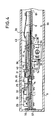
- the slide 17 also acts on an arm 36 which can be pivoted in a bearing bridge 35 formed on the intermediate floor 6 and which carries a centering mandrel 38 which is rotatably mounted on an axis 37.
- the arm 36 on which a leaf spring 39 engages, is operatively connected to the ramp 20 via a driver 40.
- a pin-slot connection 41 is used to fix the position of the arm 36 exactly in the lowered position.
- a toothed ring 43 is formed on the centering mandrel 38, to which driver tips or similar driver means, of which one is denoted by 40, are assigned on a shoulder (not shown).
- the latter is in engagement with a gear chain 44 to 48 mounted on the arm 36, the one gear wheel 48 of which is in engagement in the region of the pivot axis of the arm 36 with a stationary gear wheel 49 of the driving drive.
- the gear 49 and a worm gear 50 forming a pair of gearwheels are mounted on an axis 51 which is attached to an angle 52 fastened to the intermediate base 6.
- a worm 53 is in engagement with the worm wheel 50, which is arranged on the motor shaft of an electric motor 54 which provides the time-dependent drive of the centering mandrel 38 and which is interchangeably connected to the intermediate floor 6 by means of a plate 55.
- the electric motor 54 can be arranged in the intermediate floor in a manner similar to the electric motor 29 if the bearing bridge 35 is configured appropriately.
- the space 60 below the intermediate floor 6 is provided for electronic circuit components.
- a circuit board carrying this could be assigned to the intermediate floor 6. This creates a very flat insert, which is guided in rails 56, 57 and 58, 59 arranged on the housing.
- FIG. 3 shows that the pivoting angle of the relatively long arm 36 is very small and thus the usual tooth play between the gear wheels 48 and 49 permits a rotary movement of the gear wheel 48 transversely to the axis 51 of the gear wheel 49 without interruption of the engagement.
- FIG. 3 and 4 make the particularly low overall height of the arrangement according to the invention clear, which you rch by consistent use of space, d. H. has been achieved by a flat adaptation of the transport arrangement and drive arrangement.
- 62 denotes a slot in the plate 7, which is used to reach through the registration elements (not shown), for example a thermal print head, on an inserted chart 61.
Landscapes
- Physics & Mathematics (AREA)
- General Physics & Mathematics (AREA)
- Feeding And Guiding Record Carriers (AREA)
- Recording Measured Values (AREA)
- Holding Or Fastening Of Disk On Rotational Shaft (AREA)
- Earth Drilling (AREA)
Applications Claiming Priority (2)
| Application Number | Priority Date | Filing Date | Title |
|---|---|---|---|
| DE3629139 | 1986-08-27 | ||
| DE19863629139 DE3629139A1 (de) | 1986-08-27 | 1986-08-27 | Anordnung zum antreiben einer diagrammscheibe |
Publications (2)
| Publication Number | Publication Date |
|---|---|
| EP0265595A1 true EP0265595A1 (fr) | 1988-05-04 |
| EP0265595B1 EP0265595B1 (fr) | 1992-01-15 |
Family
ID=6308300
Family Applications (1)
| Application Number | Title | Priority Date | Filing Date |
|---|---|---|---|
| EP87109259A Expired - Lifetime EP0265595B1 (fr) | 1986-08-27 | 1987-06-27 | Dispositif d'entraînement du support de diagramme |
Country Status (4)
| Country | Link |
|---|---|
| EP (1) | EP0265595B1 (fr) |
| JP (1) | JPH0424410Y2 (fr) |
| DE (2) | DE3629139A1 (fr) |
| ES (1) | ES2029674T3 (fr) |
Citations (2)
| Publication number | Priority date | Publication date | Assignee | Title |
|---|---|---|---|---|
| DE2659642A1 (de) * | 1976-01-02 | 1977-07-14 | Thomson Brandt | Antriebsvorrichtung fuer ein videoplattenlesegeraet |
| DE2725242A1 (de) * | 1976-06-04 | 1977-12-15 | Shugart Associates | Antriebsvorrichtung fuer eine flexible magnetplatte |
Family Cites Families (1)
| Publication number | Priority date | Publication date | Assignee | Title |
|---|---|---|---|---|
| DE1266036B (de) * | 1963-04-26 | 1968-04-11 | Kienzle Apparate Gmbh | Fahrtschreiber fuer Kraftfahrzeuge |
-
1986
- 1986-08-27 DE DE19863629139 patent/DE3629139A1/de active Granted
-
1987
- 1987-06-27 DE DE8787109259T patent/DE3776072D1/de not_active Expired - Lifetime
- 1987-06-27 EP EP87109259A patent/EP0265595B1/fr not_active Expired - Lifetime
- 1987-06-27 ES ES87109259T patent/ES2029674T3/es not_active Expired - Lifetime
- 1987-08-24 JP JP12752487U patent/JPH0424410Y2/ja not_active Expired
Patent Citations (2)
| Publication number | Priority date | Publication date | Assignee | Title |
|---|---|---|---|---|
| DE2659642A1 (de) * | 1976-01-02 | 1977-07-14 | Thomson Brandt | Antriebsvorrichtung fuer ein videoplattenlesegeraet |
| DE2725242A1 (de) * | 1976-06-04 | 1977-12-15 | Shugart Associates | Antriebsvorrichtung fuer eine flexible magnetplatte |
Also Published As
| Publication number | Publication date |
|---|---|
| DE3629139C2 (fr) | 1988-06-01 |
| EP0265595B1 (fr) | 1992-01-15 |
| DE3776072D1 (de) | 1992-02-27 |
| DE3629139A1 (de) | 1988-03-10 |
| ES2029674T3 (es) | 1992-09-01 |
| JPS6344254U (fr) | 1988-03-24 |
| JPH0424410Y2 (fr) | 1992-06-09 |
Similar Documents
| Publication | Publication Date | Title |
|---|---|---|
| EP0059923B1 (fr) | Dispositif pour le positionnement d'un ruban encreur sur des pistes différentes, pour une imprimante mécanique, de préférence électromécanique | |
| EP0014948B1 (fr) | Dispositif et procédé d'impression permettant d'obtenir un espacement de caractères régulier | |
| EP0012223A1 (fr) | Enregistreur de route | |
| DE2159201C3 (de) | Vorrichtung zur Führung und Bewegung eines Lesekopfes | |
| EP0265595B1 (fr) | Dispositif d'entraînement du support de diagramme | |
| DE3108765A1 (de) | Vorrichtung zum festhalten einer zeitkarte in einem zeitschreiber, wie einer stechuhr | |
| EP0709683A1 (fr) | Arrangement des supports d'enregistrement dans un tachygraphe avec un boîtier plat | |
| EP0800151B1 (fr) | Liaison d'entraínement pour un dispositif d'enregistrement de tachygraphe | |
| EP1127700B1 (fr) | Dispositif et méthode d'impression avec guidage mobile pour tête d'impression | |
| EP0330002B1 (fr) | Dispositif de positionnement horaire exact et automatique d'un paquet de disques à diagramme pour l'enregistrement par sections mais continu | |
| DE3322791C2 (fr) | ||
| EP0368219B1 (fr) | Enregistreur de route avec des moyens d'entraînement actionnés en temps pour des portes-diagrammes servant comme support d'enregistrement | |
| EP0150354B1 (fr) | Dispositif de mesure de longueurs ou d'angles | |
| DE3642270C2 (fr) | ||
| EP0935220A2 (fr) | Tachygraphe avec un boítier parallélépipédique | |
| EP0567933B1 (fr) | Disposition pour appliquer un galet presseur | |
| EP0102595A1 (fr) | Procédé pour contrôler un élément d'enregistrement | |
| DE3138394A1 (de) | Kassettenlaufwerk mit fernbedienbarer servoeinrichtung | |
| EP1294567B1 (fr) | Module d'impression dote d'une tete d'impression a aiguille | |
| DE3618371A1 (de) | Einrichtung zum transport eines typentraegerwagens und eines aufzeichnungstraegers an schreib- oder bueromaschinen aehnlicher bauart | |
| DD220266A1 (de) | Einstellvorrichtung fuer mosaikdruckkopf | |
| DE1817340B2 (de) | Registrieranordnung fuer fahrtschreiber | |
| DE2559638B2 (de) | Bedienungsvorrichtung fuer ein tonbandgeraet | |
| DE7533843U (de) | Laufwerk eines Aufzeichnungsträgers | |
| DE7418981U (de) | Schreibaufsatz, insbesondere zur Lochschriftübersetzung |
Legal Events
| Date | Code | Title | Description |
|---|---|---|---|
| PUAI | Public reference made under article 153(3) epc to a published international application that has entered the european phase |
Free format text: ORIGINAL CODE: 0009012 |
|
| AK | Designated contracting states |
Kind code of ref document: A1 Designated state(s): DE ES FR GB IT |
|
| 17P | Request for examination filed |
Effective date: 19880531 |
|
| 17Q | First examination report despatched |
Effective date: 19910123 |
|
| GRAA | (expected) grant |
Free format text: ORIGINAL CODE: 0009210 |
|
| AK | Designated contracting states |
Kind code of ref document: B1 Designated state(s): DE ES FR GB IT |
|
| REF | Corresponds to: |
Ref document number: 3776072 Country of ref document: DE Date of ref document: 19920227 |
|
| ITF | It: translation for a ep patent filed | ||
| GBT | Gb: translation of ep patent filed (gb section 77(6)(a)/1977) | ||
| ET | Fr: translation filed | ||
| REG | Reference to a national code |
Ref country code: ES Ref legal event code: FG2A Ref document number: 2029674 Country of ref document: ES Kind code of ref document: T3 |
|
| PLBE | No opposition filed within time limit |
Free format text: ORIGINAL CODE: 0009261 |
|
| STAA | Information on the status of an ep patent application or granted ep patent |
Free format text: STATUS: NO OPPOSITION FILED WITHIN TIME LIMIT |
|
| 26N | No opposition filed | ||
| PGFP | Annual fee paid to national office [announced via postgrant information from national office to epo] |
Ref country code: ES Payment date: 19940614 Year of fee payment: 8 |
|
| PG25 | Lapsed in a contracting state [announced via postgrant information from national office to epo] |
Ref country code: ES Free format text: LAPSE BECAUSE OF THE APPLICANT RENOUNCES Effective date: 19950628 |
|
| PGFP | Annual fee paid to national office [announced via postgrant information from national office to epo] |
Ref country code: FR Payment date: 19990512 Year of fee payment: 13 |
|
| REG | Reference to a national code |
Ref country code: ES Ref legal event code: FD2A Effective date: 19991007 |
|
| PGFP | Annual fee paid to national office [announced via postgrant information from national office to epo] |
Ref country code: GB Payment date: 20000512 Year of fee payment: 14 |
|
| PG25 | Lapsed in a contracting state [announced via postgrant information from national office to epo] |
Ref country code: FR Free format text: LAPSE BECAUSE OF NON-PAYMENT OF DUE FEES Effective date: 20010228 |
|
| REG | Reference to a national code |
Ref country code: FR Ref legal event code: ST |
|
| PG25 | Lapsed in a contracting state [announced via postgrant information from national office to epo] |
Ref country code: GB Free format text: LAPSE BECAUSE OF NON-PAYMENT OF DUE FEES Effective date: 20010627 |
|
| GBPC | Gb: european patent ceased through non-payment of renewal fee |
Effective date: 20010627 |
|
| PGFP | Annual fee paid to national office [announced via postgrant information from national office to epo] |
Ref country code: DE Payment date: 20040819 Year of fee payment: 18 |
|
| PG25 | Lapsed in a contracting state [announced via postgrant information from national office to epo] |
Ref country code: IT Free format text: LAPSE BECAUSE OF NON-PAYMENT OF DUE FEES;WARNING: LAPSES OF ITALIAN PATENTS WITH EFFECTIVE DATE BEFORE 2007 MAY HAVE OCCURRED AT ANY TIME BEFORE 2007. THE CORRECT EFFECTIVE DATE MAY BE DIFFERENT FROM THE ONE RECORDED. Effective date: 20050627 |
|
| PG25 | Lapsed in a contracting state [announced via postgrant information from national office to epo] |
Ref country code: DE Free format text: LAPSE BECAUSE OF NON-PAYMENT OF DUE FEES Effective date: 20060103 |