EP0265700B1 - Procédé et installation pour le contrôle de la traction de la bande dans un four de recuit en continu - Google Patents
Procédé et installation pour le contrôle de la traction de la bande dans un four de recuit en continu Download PDFInfo
- Publication number
- EP0265700B1 EP0265700B1 EP87114304A EP87114304A EP0265700B1 EP 0265700 B1 EP0265700 B1 EP 0265700B1 EP 87114304 A EP87114304 A EP 87114304A EP 87114304 A EP87114304 A EP 87114304A EP 0265700 B1 EP0265700 B1 EP 0265700B1
- Authority
- EP
- European Patent Office
- Prior art keywords
- tension
- metal strip
- roll
- magnitude
- exerted
- Prior art date
- Legal status (The legal status is an assumption and is not a legal conclusion. Google has not performed a legal analysis and makes no representation as to the accuracy of the status listed.)
- Expired - Lifetime
Links
- 239000002184 metal Substances 0.000 title claims description 151
- 229910052751 metal Inorganic materials 0.000 title claims description 151
- 238000000137 annealing Methods 0.000 title claims description 81
- 238000000034 method Methods 0.000 title claims description 17
- 238000001816 cooling Methods 0.000 claims description 50
- 238000010438 heat treatment Methods 0.000 claims description 46
- 229910001209 Low-carbon steel Inorganic materials 0.000 claims description 28
- 230000008859 change Effects 0.000 claims description 12
- 238000012544 monitoring process Methods 0.000 claims description 12
- 239000000203 mixture Substances 0.000 claims description 5
- 230000000063 preceeding effect Effects 0.000 claims 3
- 238000002791 soaking Methods 0.000 description 26
- 238000012937 correction Methods 0.000 description 22
- 229910000831 Steel Inorganic materials 0.000 description 10
- 239000010959 steel Substances 0.000 description 10
- 229910052799 carbon Inorganic materials 0.000 description 7
- OKTJSMMVPCPJKN-UHFFFAOYSA-N Carbon Chemical compound [C] OKTJSMMVPCPJKN-UHFFFAOYSA-N 0.000 description 5
- 238000010276 construction Methods 0.000 description 5
- 230000008569 process Effects 0.000 description 4
- 230000000712 assembly Effects 0.000 description 3
- 238000000429 assembly Methods 0.000 description 3
- 238000004891 communication Methods 0.000 description 3
- 238000005516 engineering process Methods 0.000 description 3
- 238000001953 recrystallisation Methods 0.000 description 3
- 238000011144 upstream manufacturing Methods 0.000 description 3
- 230000032683 aging Effects 0.000 description 2
- 239000007789 gas Substances 0.000 description 2
- 230000002265 prevention Effects 0.000 description 2
- 230000009467 reduction Effects 0.000 description 2
- 230000002829 reductive effect Effects 0.000 description 2
- 239000005028 tinplate Substances 0.000 description 2
- 230000004323 axial length Effects 0.000 description 1
- 238000005452 bending Methods 0.000 description 1
- 230000015572 biosynthetic process Effects 0.000 description 1
- 239000000112 cooling gas Substances 0.000 description 1
- 238000002425 crystallisation Methods 0.000 description 1
- 230000008025 crystallization Effects 0.000 description 1
- 230000003247 decreasing effect Effects 0.000 description 1
- 238000010586 diagram Methods 0.000 description 1
- 238000004519 manufacturing process Methods 0.000 description 1
- 238000012986 modification Methods 0.000 description 1
- 230000004048 modification Effects 0.000 description 1
- 230000002093 peripheral effect Effects 0.000 description 1
- 238000012545 processing Methods 0.000 description 1
- 230000005855 radiation Effects 0.000 description 1
- 238000007670 refining Methods 0.000 description 1
- 230000004044 response Effects 0.000 description 1
- 238000013000 roll bending Methods 0.000 description 1
Images



Classifications
-
- C—CHEMISTRY; METALLURGY
- C21—METALLURGY OF IRON
- C21D—MODIFYING THE PHYSICAL STRUCTURE OF FERROUS METALS; GENERAL DEVICES FOR HEAT TREATMENT OF FERROUS OR NON-FERROUS METALS OR ALLOYS; MAKING METAL MALLEABLE, e.g. BY DECARBURISATION OR TEMPERING
- C21D9/00—Heat treatment, e.g. annealing, hardening, quenching or tempering, adapted for particular articles; Furnaces therefor
- C21D9/52—Heat treatment, e.g. annealing, hardening, quenching or tempering, adapted for particular articles; Furnaces therefor for wires; for strips ; for rods of unlimited length
-
- C—CHEMISTRY; METALLURGY
- C21—METALLURGY OF IRON
- C21D—MODIFYING THE PHYSICAL STRUCTURE OF FERROUS METALS; GENERAL DEVICES FOR HEAT TREATMENT OF FERROUS OR NON-FERROUS METALS OR ALLOYS; MAKING METAL MALLEABLE, e.g. BY DECARBURISATION OR TEMPERING
- C21D9/00—Heat treatment, e.g. annealing, hardening, quenching or tempering, adapted for particular articles; Furnaces therefor
- C21D9/52—Heat treatment, e.g. annealing, hardening, quenching or tempering, adapted for particular articles; Furnaces therefor for wires; for strips ; for rods of unlimited length
- C21D9/54—Furnaces for treating strips or wire
- C21D9/56—Continuous furnaces for strip or wire
Definitions
- the present invention relates generally to a method and system for controlling tension to be exerted on a metal strip in a continuous annealing furnace for preventing the metal strip from meandering in the annealing furnace. More specifically, the invention relates to a technique for controlling tension on the metal strip in the continuous annealing furnace relative to thermal crown magnitude for suppressing meandering of the metal strip. The invention also relates to tension control for annealing a very thin and flexible low-carbon or extra low-carbon steel strip.
- continuous annealing of a series of metal strip is performed in a continuous annealing furnace which defines path of the metal strip by means of a vertically offset plurality of hearth rolls.
- the series of metal strip passes substantially long path in the annealing furnace with wrapping over the hearth rolls.
- the offset magnitude can be amplified by substantial length of the metal strip to cause substantial meandering of the metal strip in the furnace. This can cause breakage of the metal strip by contacting with the peripheral wall of the annealing furnace. Therefore, meandering of the metal strip has to be suppressed for stably performing continuous annealing operation.
- a crown is provided on the hearth rolls for automatically suppressing meandering of the metal strip by exerting centering force.
- taper crown which gradually reduces diameter of the roll at both ends to formed tapered profile at end portion
- round crown which reduces diameter of the roll for forming, rounded profile at both ends of the roll
- taper crown has widely used because of ease of production and better centering performance.
- the flexible metal strip tightly wraps on the periphery of the hearth roll. At this condition, force to transversely shift the metal strip toward the section having larger diameter is exerted. This transverse force serves as centering force for centering the metal strip.
- the magnitude of the centering force is variable depending upon magnitude of tension exerted on the metal strip. Namely, the magnitude of centering force to be exerted on the metal strip increases as increasing the magnitude of the tension to be exerted on the metal strip. This mean that greater magnitude of tension force to be exerted on the metal strip may exhibit better strip centering performance. However, the tension to be exerted on the metal strip is limited in view of the strength of the metal strip to be annealed so that breakage or deformation of the metal strip may not occur.
- the metal strip is centered to constantly pass the central portion of the hearth roll to form a cover for the central portion of the roll. Therefore, while wrapped by the metal strip in a heating zone and soaking zone in the annealing furnace, the central portion of the hearth roll may not subject the heat in the furnace.
- the transverse end sections where the crown is provided constantly subject the heat in the furnace As a result, difference of the thermal expansion in the radial direction between the central portion and the end portions occurs. In this case, the thermal expansion at the end portions becomes much greater than that in the central portion. This difference of the thermal expansion causes reduction of the magnitude of crown on the hearth roll to reduce centering force to be exerted on the metal strip. When the difference of the thermal expansion becomes significant, substantial change of roll crown is caused to result in meandering or heat bu ckling of the metal strip.
- the central portion constantly subject high temperature heat transmitted from the metal strip to differentiate the temperature between the central portion and the end portion. Because of higher temperature at the central portion, thermal crown tends to be increased.
- annealing metal strip such as a soft-temper tin plate, tin-free strip (TFS), which has carbon amount lower than or equal to 100 ppm. crown of the hearth roll and the tension to be exerted on the strip has to be quite delicately controlled so as not to cause meandering and heat buckle.
- TFS tin-free strip
- JP 60-21335 discloses a technology, in vhich distances to a plurality of laterally oriented measuring points are measured. Uhen difference of distance over laterally oriented measuring points is observed, the judgeent can be made that heat buckle has been caused. Prevention of heat buckle is done by controlling at least one of heating zone temperature, soaking zone temperature, cooling speed, strip speed, tension of the strip and so forth.
- JP 58-61232 there is disclosed a heat buckle preventing technology in *hich the strategy has been taken to measure strip temperature, strip tension and the lateral temperature gradient and to arithmetically estimate the critical tension based on lateral temperature gradient and strip temperature.
- the obtained critical tension is compared vith the measured strip tension in order to generate an aIarm signaI vhen the measured strip tension is greater than or equal to the critical tension.
- the line speed viII be lovered in response to the alarm signal for preventing the strip from causing heat buckle.
- Another object of the invention is to provide a method and device for controlling tension in a continuous annealing furnace which is applicable for continuous annealing of very thin and flexible extra low carbon metal trip.
- An annealing operation is performed with controlling tension force to be exerted on a metal strip depending upon thermal crown of hearth rolls.
- the thermal crown magnitude is assumed based on various factors influencing for the magnitude of the effective crown.
- tension may also be adjusted according to content of Ti and Nb.
- a device for controlling tension to be exerted on a metal strip in a continuous annealing furnace which includes a plurality of hearth rolls for defining a path for the metal strip, comprises first means for exerting tension for the metal strip traveling through the continuous annealing furnace along the path, second means for monitoring a preselected operation parameter of the annealing furnace, which operation parameter affects for variation of magnitude of effective roll crown on the hearth rolls, third means for deriving an assumed effective roll crown magnitude on the basis of the operation parameter as monitored by the second means, and fourth means for deriving an optimum tension range on the basis of the operation parameter and controlling the first means for adjusting tension to be exerted on the metal strip so that tension to be actually exerted on the metal strip can be maintained within the optimum tension range.
- a device for controlling tension for a continuous annealing furnace which includes a plurality of hearth rolls for defining a path for the metal strip, comprises first means for exerting tension for the metal strip traveling through the continuous annealing furnace along the path, second means for monitoring a preselected operation parameter of the annealing furnace, which operation parameter affects for variation of magnitude of effective roll crown on the hearth rolls, third means for deriving an assumed effective roll crown magnitude on the basis of the operation parameter as monitored by the second means, and fourth means for deriving an optimum tension range on the basis of the operation parameter and controlling the first means for adjusting tension to be exerted on the metal strip so that tension to be actually exerted on the metal strip can be maintained within the optimum tension range, the fourth means deriving the optimum tension range for annealing an extra low carbon steel strip in relation to the effective crown magnitude of the hearth roll in such a manner that, when tension to be exerted on the extra low carbon steel strip is y kg/mm2 and
- the first means comprises a first, second and third bridle rolls, the first bridle roll being arranged at the entrance of the annealing furnace, the second bridle roll being arranged at the outlet of the annealing furnace and a third bridle roll being disposed within the annealing furnace and on the metal strip path, the first, second and third bridle rolls being cooperative to each other for adjusting tension to be exerted on the metal strip, and the fourth means controls rotation speed of respective of the first, second and third bridle rolls for adjusting tension to be within the optimum tension range.
- the third bridle roll is drive at a predetermined speed and the fourth means adjusts rotation speeds of the first and second bridle rolls in relation to the rotation speed of the third bridle roll for maintain the tension within the optimum tension range.
- the second means monitors temperature within the annealing furnace as a parameter for causing thermal change of the roll crown, and the third means derives assumed temperature distribution on various section of the hearth roll on the basis of the monitored temperature and a line speed of the metal strip for assuming thermal change of roll crown magnitude.
- the second means further monitor actual tension exerted on the metal strip traveling through the annealing furnace
- the fourth means derives so the optimum tension and compares criteria defining the optimum tension with the actual tension as monitored by the second means for adjusting rotation speed of the first and second bridle rolls based on a difference between the optimum tension range indicative criteria and the actual tension.
- the system may further comprises fifth means for rotatingly drive the hearth rolls, the fourth means is cooperative with the fifth means for adjusting tension of the metal strip within the optimum tension range in cooperation with the second means.
- the fifth means controls rotation speed of respective hearth rolls for adjusting the tension to be exerted on the metal strip.
- the fourth means derives the optimum tension range in view of the composition of the metal strip to be annealed.
- the annealing furnace is divided into a heating stage and a cooling state
- the second means monitors the operating parameters in the heating stage and cooling stage separately to each other
- the third means derives assumed effective roll crown magnitude of hearth rolls disposed in the heating stage and cooling stage separately to each other
- the fourth means controls tension of metal strip traveling in the heating stage and cooling stage independently of each other.
- a method for controlling tension to be exerted on a metal strip in a continuous annealing furnace including a plurality of hearth rolls provided with a given magnitude of roll crown comprising the steps of:
- the method may further comprise a step of monitoring actual tension exerted on the metal strip, and the control of rotation speed of the bridle rolls is performed on the basis of a difference between the actual tension and the target tension so as to reduce the difference to zero.
- the rotation speed of respective the bridle rolls is determined with reference to predetermined one of bridle roll.
- the step of monitoring operation parameter are monitored temperature of atmosphere in the annealing furnace and a line speed of the metal strip, and the assumed roll crown magnitude is derived on the basis of the monitored temperature and the line speed.
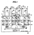
- Fig. 1 is a diagramatical illustration of a continuous annealing furnace associated with the preferred embodiment of a tension control system according to the invention, which tension control system are shown in a form of a block diagram;
- Fig. 2 is a chart showing variation of tension relative to variation of line speed
- Fig. 3 is a front elevation of a hearth roll showing dimensions of the various section thereof;
- Fig. 4 is a graph showing relationship between an effective roll crown and a unit tension with respect to various metal strips having different proportions in width and thickness;
- Fig. 5 is a chart showing optimal relationship between the effective roll crown and the tension force to be exer ted on the low-carbon steel strip
- FIGs. 6(A), 6(B) and 6(C) are partial illustration of the hearth roll, in which Fig. 6(A) shows an initial configuration of the hearth roll with an initial roll crown, Fig. 6(B) shows a hearth roll to be disposed within a heating zone or soaking zone in the continuous annealing furnace, and Fig. 6(C) is shown the hearth roll disposed within a cooling zone in the continuous annealing furnace;
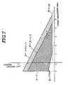
- Fig. 7 is a graph showing relationship of an actual roll crown and a unit tension in an experimentation for annealing an extra low-carbon steel strips with various composition
- Fig. 8 is a chart showing variation of roll crown
- Fig. 9 is a graph showing variation of temperatures at various portion on the hearth roll.
- the continuous annealing furnace is generally constituted by a heating zone 2, a soaking zone 3, a moderate cooling zone 4 and a rapid cooling zone 5.
- the heating zone 2 is oriented at the entrance 1a of the furnace 1 to heat a series of metal strip S fed into the furnace to a predetermined temperature.
- the metal strip S is held at the predetermined temperature. Therefore, in the heating zone 2 and the soaking zone 3, there are provided a known heating device to maintain the temperatures.
- the moderate cooling zone 4 follows the soaking zone 3 for gradually or moderately cooling the metal strip according to a predetermined cooling pattern which is determined with respect to the target product.
- the metal strip past the moderate cooling zone is fed into the rapid cooling zone 5 to be cooled rapidly and fed out from the furnace through an outlet 1b
- Communication paths 2a, 3a and 4a are formed for connecting respective zones 2, 3, 4 and 5. These communication paths 2a, 3a and 4a thus establish series of metal strip path throughout the continuous annealing furnace. Therefore, the series of metal strip S is continuously fed through the annealing furnace to be subject annealing heat treatment through the furnace.
- a leveling device and a looper may be provided upstream of the furnace.
- the leveling device serves for flattening the metal strip by heating bending in a per se known manner.
- the looper is interposed between the leveling device and the entrance 1a of the annealing furnace 1 for compensating variation of line speed at the upstream of the furnace.
- the metal strip S is fed, at first, into the heating zone 2 via a roll seal (not shown) provided at the inlet to be heated in the reductive atmosphere in the furnace chamber.
- a radiant tube burner or other heating device is provided in the heating zone heating the furnace chamber.
- Another radiant tube burner or other heating device is also provided in the soaking zone 3 for evenly maintaining a section of the metal strip S at a predetermined temperature.
- the metal strip S is brought near the predetermined temperature in the heating zone 2. Therefore, the heating device in the soaking zone may merely provide enough heat to prevent temperature drop in the metal strip due to radiation of heat.
- the respective heating devices in the heating zone 2, and the soaking zone 3 are designed to be controlled according to the desired patterns of heat cycles.
- Gas jets are provided at both sides of the metal strip path in the rapid cooling zone 5.
- the cooling gas from the gas jets is discharged onto both surfaces of the metal strip for cooling the metal strip to approximately 70°C to 90°C.
- a plurality of hearth rolls 6 are arranged within respective heating zone 2, the soaking zone 3, the moderate cooling zone 4 and the rapid c ooling zone 5 for defining a metal strip path.
- the hearth rolls are separated into two groups, one of which are oriented adjacent the ceiling of the furnace and the other are oriented adjacent the floor of the furnace.
- the hearth rolls arranged at the position close to the ceiling of the furnace may be hereafter referred to as "upper-side hearth roll” and the hearth rolls located adjacent the floor of the furnace may be referred to as "lower-side hearth roll".
- the metal strip S in the furnace is wrapped around the upper- and lower-side hearth rolls 6 alternatively to travel along a zig-zag path in the furnace.
- Bridle roll assembly 8 is arranged immediately upstream of the entrance 1a of the furnace. Similarly, a bridle roll assembly 10 is arranged immediately down-stream of the outlet 1b of the furnace. An additional bridle roll assembly 9 is disposed in the communication path 3a.
- the bridle roll assemblies 8, 9 and 10 respective include bridle roll 8a, 9a and 10a.
- the bridle rolls 8a, 9a and 10a are respectively associated with drive motors 12, 13 and 14 to be rotatingly driven at a controlled speed.
- each of the driving motor 12, 13 and 14 are variable of revolution speed according to a driving voltage to be applied.
- the bridle roll assemblies 8 and 9 are cooperative to each other for adjusting tension force to be exerted on the metal strip S in the heating zone 2 and the soaking zone 3.
- the bridle roll assembly 9 is also associated with the bridle roll assembly 10 for controlling tension force to be exerted on the metal strip S in the moderate cooling zone 4 and the rapid cooling zone 5.
- the hearth rolls 6 are also associated with driving motors 12 to be rotatingly driven at a controlled speed.
- the hearth rolls 6 as driven at the controlled speed are cooperative with the bridle roll assemblies 8, 9 and 10 for adjusting the tension force to be exerted on the metal strip.
- the driving motors 11 are variable of revolution speed for adjusting the rotation speed of the hearth rolls 6 according to an electric voltage to be applied.
- a control circuit 100 is provided.
- the control circuit 100 is connected to tension sensors 102a, 102b, 102c, 102d, 102e and 102f which are provided adjacent or on the some of the hearth rolls for monitoring the tension of the metal strip S.
- the tension sensors 102a, 102b, 102c, 102d, 102e and 102f will be represented by reference numeral "102" as generally referred to.
- Each of the tension sensors 102 produces a tension indicative sensor signal.
- the control circuit 100 is also connected to a temperature sensors 104a, 104b, 104c and 104d are disposed within respective heating zone 2, the soaking zone 3, the moderate cooling zone 4 and the rapid cooling zone 5 for monitoring the temperature of atmosphere in respectively associated zones, which temperature sensors as generally referred to may be represented by the reference numeral "104" in the following disclosure.
- Each of the temperature sensor 104 produces a temperature indicative sensor signal.
- the control circuit 100 is connected to a motor speed sensor 106 which monitors revolution speed of the motor 13.
- the motor speed sensor 106 produces a motor speed indicative sensor signal.
- the shown embodiment employs a single motor speed sensor, it would be possible to provide the same motor speed sensors for a plurality of motors or for all of the motors.
- the control circuit 100 may be a computer-based circuit for processing preselected operation parameters to derive rotation speeds of respective hearth rolls 6, bridle rolls 8a, 9a and 10a and whereby controlling tension force to be exerted on the metal strip.
- the control circuit 100 includes arithmetic circuits 108 and 110.
- the arithmetic circuit 108 is designed for deriving target tension to be exerted on the metal strip S in the heating zone 2 and the soaking zone 3.
- the arithmetic circuit 110 is designed for deriving a target tension to be exerted on the metal strip S in the moderate cooling zone 4 and the rapid cooling zone 5.
- the arithmetic circuit 108 receives the temperature indicative sensor signals from the temperature sensors 104 in the heating zone 2 and the soaking zone. Furthermore, the arithmetic circuit 108 is connected to a manual input unit 112 to receive therefrom a data indicative of proportion of the width (l) and thickness (d) of the metal strip S to be treated, which proportion may be hereafter referred to as "l/d value". Via the manual input unit 112, a data indicative of the line speed of the metal strip.
- the arithmetic circuit 110 receives the temperature indicative sensor signals from the temperature sensors 104 in the moderate cooling zone 4 and the zone 5.
- the arithmetic circuit 110 also receives the motor speed indicative signal from the motor speed sensor 106.
- the arithmetic circuit 108 is connected to a manual input unit 112 to receive therefrom a data indicative of proportion of the width (l) and thickness (d) of the metal strip S to be treated, which proportion may be hereafter referred to as "l/d value". Via the manual input unit 112, a data indicative of the line speed of the metal strip.
- the arithmetic circuits 108 and 110 derives the target tensions for respectively associated zones on the basis of the input data.
- the target tension is determined in relation to the line speed of the metal strip in the furnace and to an assumed roll crown.
- the hearth roll 6 is formed taper crown with tapered periphery at both axial ends of the roll.
- the hearth roll 6 has diameter D1 at the axial center portion between points 6a - 6a where taper periphery extends.
- the hearth roll 6 has an axial length longer than the width l of the metal strip.
- the hearth roll has a diameter D2 at a point TR2 which corresponding to the lateral edge of the metal strip.
- the magnitude of effective crown Tc can be calculated by the following equation:
- Tc D1(1 + ⁇ . ⁇ T1) - D2(1 + ⁇ . ⁇ T2)
- ⁇ is a linear expansion coefficient
- the temperature of various sections of the hearth roll 6 tend to be different from each other. Namely, when the hearth roll 6 in the heating zone 2 and the soaking zone 3, the central portion of the hearth roll is covered by and held in contact with the surface of the metal strip S to be heat-treated. Therefore. the temperature of the central portion of the hearth roll 6 is held at a corresponding the temperature of the metal strip S. On the other hand, at the both axial end portion, the hearth roll directly subject the heat in the heating zone. Therefore, the temperature at both axial ends substantially corresponds to the temperature of the heating and soaking zones, respectively. As a result, greater thermal expansion occurs at the axial end sections than that in he central portion.
- the roll crown tends to be reduced from the initial configuration as shown in Fig. 6(A) to that shown in Fig. 6(B). Reduction of magnitude of the effective roll crown causes lowering of the centering force to be exerted on the metal strip to cause meandering.
- the central portion is subject relatively high temperature of the metal strip.
- the axial end portions are exposed to the cooling atmosphere. Therefore, the temperature at the central portion becomes higher than that at the axial end portions. Thermal expansion at the central portion becomes much greater than that at the axial end portions to cause change of the effective roll crown to that shown in Fig. 6(C). Increasing of magnitude of the roll crown tends to cause heat buckling. Especially possibility of causing heat buckling becomes much higher when the line speed is lowered.
- Magnitude of variation of magnitude of the effective crown also occurs depending upon change of the line speed. If the line speed is rapidly changed, temperature of the metal strip S changes rapidly. Accordingly, the temperature at the central portion of the hearth roll 6 changes rapidly. On the other hand, the temperature of atmosphere changes relatively modelately. Therefore, change speed of the temperature at the axial end portions is relatively low. This also causes variation of thermal crown.
- tendency of the meandering and thermal buckling varies depending upon the proportion (l/d) of the metal strip to be annealed. Namely, when the l/d value is great possibility of causing meandering is relatively low and possibility of causing thermal buckling is relatively high. On the other hand, when the l/d value is small, the possibility of causing meandering is high but possibility of causing thermal buckling is low.
- the tension force to be exerted on the metal strip has to be appropriately controlled.
- Fig. 4 shows relationship between the effective roll crown magnitude and the unit tension to be exerted on the metal strips having different l/d values.
- the hutched range is considered as an optimal range for the actual and practical l/d value range of metal strips. Therefore, the tension control system set forth above controls rotation speeds of the bridle rolls 8a, 9a and 10a and the hearth rolls 6 so that the tension force to be exerted on the metal strip can be maintained at this optimal range.
- allowable maximum tension (kgf/mm2) in relation to the effective crown magnitude (mm) is as shown by a line A
- allowable minimum tension is as shown in line B.
- the allowable maximum tension in relation to the effective crown magnitude is as shown by line C
- the allowable minimum tension is as shown by line D.
- the allowable maximum tension of the metal strip having the l/d value of 1.5 ⁇ 103 (line A) is greater than the allowable maximum tension of the metal strip of the l/d value of 5.5 ⁇ 103 ( line C).
- the allowable minimum tension (line D) of the metal strip of the l/d value of 5.5 ⁇ 103 is less than that (line B) of the metal strip of the l/d value of 1.5 ⁇ 103. Therefore, the hutched range is determined in a range defined by lines C and B.
- the allowable minimum tension is determined in view of performance of the tension control apparatus, so that stable tension can be obtained.
- the value of the optimal range is set at -1.
- a roll speed control circuit 113 is provided for controlling the revolution speed of the motor 13 which drives the bridle roll 9a of the intermediate bridle roll assembly 9.
- the roll speed control circuit 113 receives a roll speed reference which may be input through the manual input unit 112 and defines the basic rotation speed of the rolls.
- the roll speed control circuit 113 is also connected to the motor speed sensor 106 which monitors revolution speed of the motor 13, to receive therefrom a motor speed indicative signal.
- the roll speed control circuit 113 compares the motor speed indicative signal value with the basic rotation speed reference value to adjust a drive signal voltage for adjusting the revolution speed of the motor 13 at the basic rotation speed as set.
- the arithmetic circuit 108 and 110 receives the data indicative of the l/d value of the metal strip S to be annealed and the temperature indicative sensor signals from the temperature Sensors 104a, 104b, 104c and 104 respectively disposed in the heating zone 2, the soaking zone 3, the moderate cooling zone 4 and the rapid cooling zone 5.
- the arithmetic circuit 108 is also connected to the motor speed sensor 106 to receive therefrom the motor speed indicative signal indicative of the revolution speed of the motor 13. This motor speed indicative signal value serves as the line speed indicative data.
- the arithmetic circuits 108 and 110 also receives the driver signal output from the roller speed control circuit 113 as a signal indicative of the roll speed of the bridle roll 13.
- the arithmetic circuits 108 and 110 derives the assumed temperature of the central portion and axial end portions of the hearth rolls 6 in the heating zone 2 and the soaking zone 3 on the basis of the temperature indicative sensor signals from the temperature sensors 104a and 104b and the line speed of the metal strip S.
- relationship between the assumed temperature at the central portion and the axial end portions, the atmosphere temperature in the heating zone and soaking zone and the line speed may be experimentally derived.
- the temperature at the axial end portions of the hearth rolls in the heating zone and the soaking zone substantially correspond to the temperature of the atmosphere in the heating zone and the soaking zone. Therefore, assumption will be made that the temperature of the axial end portions correspond to the temperature as indicated by the temperature indicative sensor signals.
- temperature drop at the central portion relative to the atmosphere temperature may variable depending upon the line speed of the metal strip S. The temperature drop may be experimentally derived in terms of the line speed.
- the arithmetic circuit 108 derives the magnitude Tc of the effective roll crown on the hearth roll by the equation set forth above. Based on the effective roll crown magnitudes on the hearth rolls in the heating zone and soaking zone, the arithmetic circuit 108 determines the target tension so that the tension may be within the hutched region. Based on the derived target tension value, the arithmetic circuit 108 outputs a target tension indicative signal.
- the effective crown magnitude may be directly derived by looking up a preset table in terms of the temperature indicative signal value and the line speed data.
- the effective crown table may be set in the arithmetic circuit 108, which table may be derived from experimentations.
- the temperature of the central portion of the hearth rolls 6 disposed in the moderate cooling zone 4 and the rapid cooling zone 5 substantially corresponds to that of the metal strip S traveling through the moderate cooling zone and the rapid cooling zone.
- the axial end portions of the hear rolls 6 are exposed to the atmosphere. Therefore, the temperature in the axial end portions of the hearth rolls 6 is lower than that in the central portion.
- the magnitude of difference of the temperatures at central portion and the axial end portions is variable depending upon the line speed. Therefore, the temperature at the central portion may be assumed on the basis of the line speed and the temperatures as indicated by the temperature indicative signals from the temperature sensors 104c and 104d.
- the temperatures at the axial end portion of the hearth rolls 6 in the moderate cooling zone 4 and the rapid cooling zone are represented by the temperature indicative sensor signal values.
- effective crown magnitude is assumed by the arithmetic circuit 110.
- a table to be looked-up in terms of the temperature indicative sensor signal value and the line speed may be set in the arithmetic circuit.
- the arithmetic circuit 110 thus derives the target tension so that the tension value is within the hutched area of Fig. 5 in terms of the assumed effective crown magnitude of the hearth rolls 6 in the moderate cooling zone 4 and the rapid cooling zone.
- the arithmetic circuit 108 is connected to a tension control circuits 114, 116 and 118.
- the tension control circuit 114 is designed to determine a correction value the rotation speed of the bridle roll 8a on the basis of the tension indicative sensor signal from the tension sensor 102a and the target tension as derived by the arithmetic circuit 108.
- a correction value of the rotation speed of the bridle roll 8a is determined on the basis of the difference between the actually measured tension by the tension sensor 102a and the target tension.
- the tension control circuit 114 thus produced a correction signal indicative of the correction value of the rotation speed of the bridle roll 8a.
- the correction signal is fed to a roll speed control circuit 120.
- the roll speed control circuit 118 receives a basic roll speed reference signal which may be set through the manual input unit 112.
- the roll speed control circuit 120 derives a rotation speed of the bridle roll 8a on the basis of the roll speed reference signal value and the value of the correction signal input from the tension control circuit 114. Based on the derived rotation speed of the bridle roll, the roll speed control circuit 120 outputs a drive signal to the motor 12 for driving the latter at the controlled speed.
- the arithmetic circuit 108 also feeds the target tension indicative signal to the tension control circuit 116.
- the tension control circuit 116 is designed to derive a correction value for controlling rotation speeds of the hearth rolls in the heating zone 2.
- the tension control circuit 116 is connected to a tension indicative sensor signal from the tension sensor 112b.
- the tension control circuit 116 derives the correction value on the basis of the tension indicative sensor signal value and the target tension indicative value.
- the tension control circuit 116 feeds a correction signal indicative of the derived correction value to a roll speed control circuit 122.
- the roll speed control circuit 122 receives the roll speed reference signal and modifies the roll speed reference signal value with the correction signal value to derive a drive signal.
- the drive signal is fed to the motor 11 to control the revolution speed of the latter and whereby control the rotation speeds of the hearth rolls in the heating zone 2.
- the target tension indicative signal of the arithmetic circuit 108 is also fed to the tension control circuit 118.
- the tension control circuit 118 derives a correction value for the basic roll speed reference for adjusting the rotation speed of the hearth rolls 6 in the soaking zone 3.
- the tension control circuit 118 thus outputs a correction signal to a roll speed control circuit 124.
- the roll speed control circuit 124 thus outputs a driver signal for driving the motor which drives the hearth rolls in the soaking zone 3. Therefore, the hearth rolls 6 in the soaking zone 3 are driven at the speed derived in the roll speed control circuit 124.
- the arithmetic circuit 110 is connected to tension control circuits 126, 128 and 130.
- the tension control circuit 126 thus receives the target tension indicative signal from the arithmetic circuit 110.
- the tension control circuit 126 is also connected to a tension sensor 102d to receive therefrom the tension indicative sensor signal.
- the tension control circuit 126 compares the tension indicative signal value with the target tension indicative signal value to derive a difference therebetween. Based on the derived difference, the tension control circuit derives a correction value to output a correction signal to a roll speed control circuit 132.
- the roll speed control circuit 132 is designed to receive the basic roll speed reference indicative signal.
- the roll speed control circuit 132 modifies the basic roll speed as represented by the basic roll speed reference indicative signal based on the correction signal from the tension control circuit.
- the roll speed control circuit 132 thus outputs a driver signal to the motor 11 which is designed to rotatingly drive the hearth rolls 6 in the moderate cooling zone 4. Therefore, the heath rolls 6 in the moderate cooling zone 4 are driven at the speed as determined by the roller speed control circuit 132.
- the arithmetic circuit 110 feeds the target tension indicative signal to the tension control circuit 128.
- the tension control circuit 128 is also connected to a tension sensor 102e to receive therefrom the tension indicative sensor signal.
- the tension control circuit 128 compares the tension indicative signal value with the target tension indicative signal value to derive a difference therebetween. Based on the derived difference, the tension control circuit 128 derives a correction value to output a correction signal to a roll speed control circuit 134.
- the roll speed control circuit 134 is designed to receive the basic roll speed reference indicative signal.
- the roll speed control circuit 134 modifies the basic roll speed as represented by the basic roll speed reference indicative signal based on the correction signal from the tension control circuit.
- the roll speed control circuit 134 thus outputs a driver signal to the motor 11 which is designed to rotatingly drive the hearth rolls 6 in the rapid cooling zone 5. Therefore, the heath rolls 6 in the rapid cooling zone 5 are driven at the speed as determined by the roller speed control circuit 134.
- the arithmetic circuit 110 further feeds the target tension indicative signal to the tension control circuit 130.
- the tension control circuit 130 is also connected to a tension sensor 102f to receive therefrom the tension indicative sensor signal.
- the tension control circuit 130 compares the tension indicative signal value with the target tension indicative signal value to derive a difference therebetween. Based on the derived difference, the tension control circuit 128 derives a correction value to output a correction signal to a roll speed control circuit 136.
- the roll speed control circuit 136 is designed to receive the basic roll speed reference indicative signal.
- the roll speed control circuit 136 modifies the basic roll speed as represented by the basic roll speed reference indicative signal based on the correction signal from the tension control circuit.
- the roll speed control cir cuit 136 thus outputs a driver signal to the motor 11 which is designed to rotatingly drive the bridle roll 10a of the bridle roll assembly 10. Therefore, the bridle roll 10a is thus driven at the speed as determined by the roller speed control circuit 136.
- arithmetic circuits 108 and 110 are employed for deriving target tensions for a plurality of rolls, it would be, of cource possible to employ the arithmetic circuits for deriving target tensions for respectively corresponding single roll.
- motor speed sensors for feedback controlling motor speed for respective motors toward desired speed as derived by the roll speed control circuits.
- Such tension control system may be applicable for annealing extra low carbon steel strip, such as strip for tin plate, TFS (tin-free strip) and so forth.
- extra low carbon steel strip such as strip for tin plate, TFS (tin-free strip) and so forth.
- TFS tin-free strip
- the extra low carbon steel particularly that for very thin surface decorative plate is classified depending upon required treatment and hardness into T1 to T6, for example.
- T indicates refining magnitude and figure following "T” represents magnitude of hardness. In the shown example, the greater value of figure represents greater hardness of the strip.
- the extra low carbon steel strip classified at T4 or above could be produced by means of the continuous annealing furnace. Namely, in case of the extra low carbon steel strip classified at T3 or below, could not be produced because it was difficult to reduce content of carbon to obtain required softness. On the other hand, the soft steel of T3 or below is often required non-aging characteristics. This also prevents such soft steel to be produced by continuous annealing process.
- the extra low carbon steel strip has higher recrystallization temperature than that of the low carbon steel strip and has lower hardness.
- the recrystallization temperature tends to be differentiated depending upon the content of Ti and/or Nb.
- hardness of the metal strip tends to be varied. Namely, the metal strip which does not contain Ti and Nb has lower recrystallization temperature. e.g. 650 °C and has greater hardness than that containing Ti and/or Nb which has higher crystallization temperature, e.g. 750 °C.
- the extra low carbon steel does not contain Ti and Nb cannot has complete non-aging characteristics.
- the appended table 1 shows typical examples of compositions of the extra low carbon steel to produce through continuous annealing process.
- Various l/d values of metal strips having the composition as shown in the table were annealed to find optimal tension value where heating bucking may not occur.
- the steel strips in a l/d value range of 1500 to 6700 were used.
- the result of experimentation is shown in Fig. 7.
- minimum effective crown magnitude was set at x ⁇ -1. After experimentations, it was found that when the effective crown magnitude becomes smaller than -1, centering force of the roll crown does not work and meandering of the metal strip could not be suppressed.
- magnitude of the roll crown varies depending upon the temperature distribution on the hearth roll. Therefore, due to difference of thermal expansion magnitude at the central portion and the axial end portions of the hearth roll, the effective crown magnitude varies to make the relationship between the effective crown magnitude and tension out of the region, as represented by point B. In order to compensate this, tension is adjusted to place the relationship between the crown magnitude and tension within the aforementioned desired region, as represented by the point C.
- the extra low carbon steel strip can be produced through the continuous annealing process without causing heat buckling and/or meandering.
Landscapes
- Chemical & Material Sciences (AREA)
- Engineering & Computer Science (AREA)
- Physics & Mathematics (AREA)
- Thermal Sciences (AREA)
- Crystallography & Structural Chemistry (AREA)
- Mechanical Engineering (AREA)
- Materials Engineering (AREA)
- Metallurgy (AREA)
- Organic Chemistry (AREA)
- Heat Treatment Of Strip Materials And Filament Materials (AREA)
Claims (14)
- Dispositif de commande de la tension à exercer sur une bande de métal dans un four de recuit en continu, qui comprend une pluralité de rouleaux de sole pour définir un trajet pour la bande de métal, comportant:
des premiers moyens en vue d'exercer une tension sur ladite bande de métal se déplaçant à travers ledit four de recuit en continu le long dudit trajet;
des seconds moyens pour contrôler un paramètre de fonctionnement préalablement choisi dudit four de recuit, lequel paramètre de fonctionnement affecte la variation d'amplitude de bombement de rouleau effectif sur lesdits rouleaux de sole ;
des troisièmes moyens pour définir une amplitude de bombement de rouleau effective supposée en fonction dudit paramètre de fonctionnement, tel que contrôlé par lesdits seconds moyens;
des quatrièmes moyens pour définir une plage de tension optimum en fonction dudit paramètre de fonctionnement et commander lesdits premiers moyens pour régler la tension à exercer sur ladite bande de métal de sorte que la tension à exercer réellement sur la bande de métal puisse être maintenue à l'intérieur de ladite plage de tension optimum, dans lequel lesdits premiers moyens comportent des premier, second et troisième rouleaux de freinage, ledit premier rouleau de freinage étant disposé à l'entrée dudit four de recuit, ledit second rouleau de freinage étant disposé à la sortie dudit four de recuit et un troisième rouleau de freinage étant disposé à l'intérieur dudit four de recuit et sur ledit trajet de la bande de métal, lesdits premier, second et troisième rouleaux de freinage coopérant entre eux pour régler la tension à exercer sur la bande de métal, et lesdits quatrièmes moyens commandent la vitesse de rotation desdits premier, second et troisième rouleaux de freinage respectifs pour régler la tension à l'intérieur de ladite plage de tension optimum et dans lequel lesdits seconds moyens contrôlent la température à l'intérieur dudit four de recuit en tant que paramètre pour provoquer une variation thermique dudit bombement de rouleau, et lesdits troisièmes moyens définissent une répartition de la température supposée sur une section variable dudit rouleau de sole en fonction de la température contrôlée et d'une vitesse linéaire de ladite bande de métal pour supposer la variation thermique de l'amplitude du bombement de rouleau. - Dispositif selon la revendication 1, dans lequel ledit troisième rouleau de freinage est entraîné à une vitesse prédéterminée et lesdits quatrièmes moyens règlent les vitesses de rotation desdits premier et second rouleaux de freinage en relation avec la vitesse de rotation dudit troisième rouleau de freinage en vue de maintenir ladite tension à l'intérieur de ladite plage de tension optimum.
- Dispositif selon la revendication 1 ou 2, dans lequel lesdits seconds moyens contrôlent en outre la tension réelle exercée sur ladite bande de métal se déplaçant à travers ledit four de recuit, lesdits quatrièmes moyens définissent ladite tension optimum et comparent des critères définissant ladite tension optimum à ladite tension réelle telle que contrôlée par lesdits seconds moyens pour régler la vitesse de rotation desdits premier et second rouleaux de freinage en fonction de critères représentatifs d'une différence entre ladite plage de tension optimum et ladite tension réelle.
- Dispositif selon l'une quelconque des revendications 1 à 3, qui comporte en outre des cinquièmes moyens pour entraîner en rotation lesdits rouleaux de sole, lesdits quatrièmes moyens coopérant avec lesdits cinquièmes moyens pour régler la tension de ladite bande de métal à l'intérieur de ladite plage de tension optimum en coopération avec lesdits seconds moyens, dans lequel lesdits cinquièmes moyens contrôlent la vitesse de rotation des rouleaux de sole respectifs pour régler la tension à exercer sur la-dite bande de métal, et dans lequel lesdits quatrièmes moyens définissent ladite plage de tension optimum en fonction de la composition de ladite bande de métal à recuire.
- Dispositif selon l'une quelconque des revendications précédentes, dans lequel lesdits quatrièmes moyens définissent ladite plage de tension optimum pour recuire une bande d'acier à teneur en carbone extrêmement faible par rapport à l'amplitude de bombement effectif dudit rouleau de foyer de telle manière que, lorsque la tension à exercer sur la bande d'acier à teneur en carbone extrêmement faible est y kg/mm² et que l'amplitude du bombement effectif est x mm, la plage est définie par les courbes représentées par (y₁ = - 0,5 x + 3) et (y₃ = - 0,2 x + 0,5) et dans lequel lesdits quatrièmes moyens définissent en outre ladite plage de tension optimum par rapport à ladite amplitude de bombernent effectif dudit rouleau de foyer par des critères représentés par (y₄ = 0,25) et (x = - 1).
- Dispositif selon l'une quelconque des revendications précédentes, dans lequel lesdits quatrièmes moyens modifient ladite plage de tension optimum pour recuire une bande d'acier à teneur en carbone extrêmement faible contenant Ti, ou Nb définie par des critères représentés par (y₂ = y₁ - 0,5) et (y₃ = - 0,2 x + 0,5) et dans lequel lesdits quatrièmes moyens définissent en outre ladite plage de tension optimum par rapport à ladite amplitude de bombement effectif dudit rouleau de foyer par des critères représentés par (Y4= 0,25) et (x = -1).
- Dispositif selon l'une quelconque des revendications précédentes, dans lequel ledit four de recuit est divisé en une section de chauffage et en une section de refroidissement, lesdits seconds moyens contrôlent lesdits paramètres de fonctionnement dans ladite section de chauffage et dans ladite section de refroidissement séparément l'une de l'autre, lesdits troisièmes moyens définissent une amplitudé de bombement de rouleau effectif supposé des rouleaux de sole disposés dans ladite section de chauffage et dans ladite section de refroidissement séparément l'une de l'autre, et lesdits quatrièmes moyens commandent la tension de la bande de métal se déplaçant dans ladite section de chauffage et dans ladite section de refroidissement indépendamment l'une de l'autre.
- Dispositif de commande de la tension pour un four de recuit en continu qui comprend une pluralité de rouleaux de sole pour définir un trajet pour la bande de métal, comportant:
des premiers moyens pour exercer une tension sur ladite bande de métal se déplaçant à travers ledit four de recuit en continu le long dudit trajet;
des seconds moyens pour contrôler un paramètre de fonctionnement préalablement choisi dudit four de recuit, lequel paramètre de fonctionnement affecte une variation de l'amplitude du bombement de rouleau effectif sur lesdits rouleaux de sole ;
des troisièmes moyens pour définir une amplitude de bombement de rouleau effectif supposée en fonction dudit paramètre de fonctionnement tel que contrôlé par lesdits seconds moyens; des quatrièmes moyens pour définir une plage de tension optimum en fonction dudit paramètre de fonctionnement et commander lesdits premiers moyens pour régler la tension à exercer sur ladite bande de métal de sorte que la tension à exercer réellement sur la bande de métal puisse être maintenue à l'intérieur de ladite plage de tension optimum, lesdits quatrièmes moyens définissant ladite plage de tension optimum pour recuire une bande d'acier à teneur en carbone extrêmement faible par rapport à l'amplitude de bombement effectif dudit rouleau de sole de telle manière que, lorsque la tension à exercer sur la bande d'acier à teneur en carbone extrêmement faible est y kg/mm² et que l'amplitude du bombement effectif est x mm, la plage est définie par les courbes représentées par (y₁' = - 0,5 x + 3 ) et (y₃ = -0,2 x + 0,5), et dans lequel lesdits quatrièmes moyens définissent en outre ladite plage de tension optimum par rapport à ladite amplitude de bombement effectif dudit rouleau de sole par des critères représentés par (y₄ = 0,25) et (x = -1). - Dispositif selon la revendication 8, dans lequel lesdits quatrièmes moyens modifient ladite plage de tension optimum pour recuire une bande d'acier à teneur en carbone extrêmement faible contenant Ti ou Nb à définir par des critères représentés par (y₂ = y₁ - 0,5) et y₃ = -0,2 x + 0,5), et dans lequel lesdits quatrièmes moyens définissent en outre ladite plage de tension optimum par rapport à ladite amplitude de bombement effectif dudit rouleau de sole par des critères représentés par (y₄ = 0,25) et (x = -1).
- Procédé de commande de la tension à exercer sur une bande de métal. dans un four de recuit en continu comprenant une pluralité de rouleaux de sole affectés d'une amplitude déterminée de bombement de rouleau, comportant les étapes consistant à:
prévoir des rouleaux de freinage le long d'un trajet de ladite bande de métal;
entraîner lesdits rouleaux de freinage à une vitesse respectivement commandée pour exercer une tension sur ladite bande de métal dans ledit four de recuit, dont l'amplitude de tension à exercer sur ladite bande de métal est déterminée selon une différence de vitesse de rotation desdits rouleaux de freinage:
contrôler un paramètre de fonctionnement du four qui affecte l'amplitude effective dudit bombement de rouleau;
définir une amplitude de bombement de rouleau effective supposée en fonction du paramètre de fonctionnement contrôlé;
définir une tension visée à exercer sur ladite bande de métal de sorte que ladite tension à exercer sur ladite bande de métal soit maintenue à l'intérieur d'une relation prédéterminée avec l'amplitude de bombement de rouleau supposée; et
commander la vitesse de rotation desdits rouleaux de freinage pour ajuster la tension à exercer sur ladite bande de métal vers ladite tension visée, comportant en outre une étape consistant à contrôler la tension réelle exercée sur ladite bande de métal, et ladite conmande de vitesse de rotation desdits rouleaux de freinage est effectuée en fonction de la différence entre la tension réelle et ladite tension visée de manière à réduire ladite différence à zéro, dans lequel la vitesse de rotation desdits rouleaux de freinage respectifs est déterminée en référence à l'un des rouleaux de freinage prédéterminé et dans lequel, au cours de ladite étape de contrôle des paramètres de fonctionnement, sont contrôlées la température de l'atmosphère dans ledit four de recuit et une vitesse linéaire de ladite bande de métal, et ladite amplitude de bombement de rouleau supposée est définie en fonction de la température et de ladite vitesse linéaire contrôlées. - Procédé selon la revendication 10, dans lequel ladite tension visée pour recuire une bande d'acier à teneur en carbone extrêmement faible est déterminée par rapport à l'amplitude de bombement de rouleau effective supposée de telle manière que, lorsque la tension à exercer sur la bande d'acier à teneur en carbone extrêmement faible est y kg/mm2et que l'amplitude de bombement effective est x mm, la plage est définie par les courbes représentées par (y₁=-0,5x + 3) et (y₃= -0,2x + 0,5).
- Procédé selon les revendications 10 et 11, dans lequel lesdits quatrièmes moyens définissent en outre ladite plage de tension optimum par rapport à ladite amplitude de bombement effectif dudit rouleau de sole par des critères représentés par (y₄=0,25) et (x=-1).
- Procédé selon l'une quelconque des revendications 10 à 12, dans lequel lesdits quatrièmes moyens modifient ladite plage de tension optimum pour recuire une bande d'acier à teneur en carbone extrêmement faible contenant Ti ou Nb à définir par des critères représentés par (y₂= y₁-0,5) et (y₃=-0,2x + 0,5).
- Procédé selon l'une quelconque des revendications 10 à 13, dans lequel lesdits quatrièmes moyens définissent en outre ladite plage de tension optimum par rapport à ladite amplitude de bombement effective dudit rouleau de sole par des critères représentés par (y₄=0,25) et (x=-1).
Applications Claiming Priority (4)
| Application Number | Priority Date | Filing Date | Title |
|---|---|---|---|
| JP61231579A JPH075995B2 (ja) | 1986-09-30 | 1986-09-30 | 連続焼鈍炉における金属ストリツプの張力制御方法 |
| JP231579/86 | 1986-09-30 | ||
| JP292955/86 | 1986-12-09 | ||
| JP61292955A JPS63145721A (ja) | 1986-12-09 | 1986-12-09 | 極低炭素鋼板の連続焼鈍方法 |
Publications (2)
| Publication Number | Publication Date |
|---|---|
| EP0265700A1 EP0265700A1 (fr) | 1988-05-04 |
| EP0265700B1 true EP0265700B1 (fr) | 1991-03-06 |
Family
ID=26529966
Family Applications (1)
| Application Number | Title | Priority Date | Filing Date |
|---|---|---|---|
| EP87114304A Expired - Lifetime EP0265700B1 (fr) | 1986-09-30 | 1987-09-30 | Procédé et installation pour le contrôle de la traction de la bande dans un four de recuit en continu |
Country Status (8)
| Country | Link |
|---|---|
| US (1) | US4878961A (fr) |
| EP (1) | EP0265700B1 (fr) |
| KR (1) | KR950006693B1 (fr) |
| AU (1) | AU598035B2 (fr) |
| BR (1) | BR8705047A (fr) |
| CA (1) | CA1280190C (fr) |
| DE (1) | DE3768418D1 (fr) |
| ES (1) | ES2021319B3 (fr) |
Cited By (1)
| Publication number | Priority date | Publication date | Assignee | Title |
|---|---|---|---|---|
| EP0754772A3 (fr) * | 1995-06-23 | 1998-07-08 | Nkk Corporation | Procédé pour contrÔler la traction d'une bande métallique dans un four de traitement thermique |
Families Citing this family (14)
| Publication number | Priority date | Publication date | Assignee | Title |
|---|---|---|---|---|
| US5497817A (en) * | 1992-05-25 | 1996-03-12 | Nippon Steel Corporation | Method for continuously annealing steel strip |
| US5827056A (en) * | 1997-01-09 | 1998-10-27 | Drever Company | Device and method for improving strip tracking in a continuous heating furnace |
| JP2002003956A (ja) * | 2000-06-27 | 2002-01-09 | Kawasaki Steel Corp | 連続熱処理炉の急冷帯前後用ロール及び急冷帯設備 |
| FR2876709B1 (fr) * | 2004-10-14 | 2007-07-27 | Kappa Thermline Soc Par Action | Procede et dispositif d'amelioration qualitative et quantitative de la production dans un four vertical de traitement de bandes d'acier ou d'aluminium |
| KR100986808B1 (ko) * | 2008-04-25 | 2010-10-08 | 주식회사 포스코 | 연속 소둔로의 장력 제어 시스템 |
| AT510468B1 (de) * | 2010-09-21 | 2012-07-15 | Voestalpine Stahl Gmbh | Durchlaufofen für ein insbesondere metallisches band |
| CN102776351B (zh) * | 2011-05-10 | 2013-07-31 | 鞍钢股份有限公司 | 一种两段式连续退火炉碳套炉底辊结瘤处理方法 |
| CN104451118B (zh) * | 2014-10-27 | 2016-08-03 | 燕山大学 | 一种适合于连续退火过程的带钢板形逐段演变预报方法 |
| CN111519016B (zh) * | 2020-04-30 | 2022-03-29 | 江苏省沙钢钢铁研究院有限公司 | 热镀锌板的制备方法、以及热镀锌板 |
| CN113201644B (zh) * | 2021-03-18 | 2023-01-17 | 兴化市广福金属制品有限公司 | 一种不锈钢带材连续退火设备及工艺 |
| CN113564337B (zh) * | 2021-07-08 | 2023-04-18 | 首钢智新迁安电磁材料有限公司 | 退火炉带钢张力的控制方法 |
| CN115287445B (zh) * | 2022-08-09 | 2023-07-25 | 太原理工大学 | 一种极薄带材退火过程中连续施加横向张力的装置和方法 |
| AT526624A1 (de) | 2022-10-18 | 2024-05-15 | Sbi Mechatronik Gmbh | Vorrichtung zur Einstellung des Spalts einer Breitschlitzdüse |
| CN119194000A (zh) * | 2024-11-29 | 2024-12-27 | 广东世创金属科技股份有限公司 | 一种基于大张力的金属带材的退火热处理设备 |
Family Cites Families (9)
| Publication number | Priority date | Publication date | Assignee | Title |
|---|---|---|---|---|
| JPS607693B2 (ja) * | 1979-10-31 | 1985-02-26 | 川崎製鉄株式会社 | 鋼帯の連続焼鈍方法 |
| JPS5943979B2 (ja) * | 1979-10-31 | 1984-10-25 | 川崎製鉄株式会社 | 炉内張力制御方法 |
| JPS6033171B2 (ja) * | 1980-06-19 | 1985-08-01 | 三菱電機株式会社 | ストリツプの炉内張力制御方法 |
| US4571274A (en) * | 1982-10-28 | 1986-02-18 | Kawasaki Steel Corporation | Method for continuous annealing of a metal strip |
| JPS59116325A (ja) * | 1982-12-22 | 1984-07-05 | Kawasaki Steel Corp | 極低炭素鋼帯の連続焼鈍方法 |
| JPS60181242A (ja) * | 1984-02-28 | 1985-09-14 | Kawasaki Steel Corp | 鋼帯の連続焼鈍方法 |
| JPS6140728A (ja) * | 1984-08-02 | 1986-02-27 | ジヨ−ジ・アレキス・ペロフ | おもり |
| JPS61194119A (ja) * | 1985-02-21 | 1986-08-28 | Nippon Steel Corp | 連続焼鈍設備における鋼帯冷却方法 |
| JPS61243126A (ja) * | 1985-04-18 | 1986-10-29 | Nippon Steel Corp | 熱処理炉における板幅制御方法 |
-
1987
- 1987-09-29 CA CA000548081A patent/CA1280190C/fr not_active Expired - Lifetime
- 1987-09-30 DE DE8787114304T patent/DE3768418D1/de not_active Expired - Lifetime
- 1987-09-30 KR KR1019870010959A patent/KR950006693B1/ko not_active Expired - Fee Related
- 1987-09-30 AU AU79210/87A patent/AU598035B2/en not_active Ceased
- 1987-09-30 BR BR8705047A patent/BR8705047A/pt not_active IP Right Cessation
- 1987-09-30 US US07/102,875 patent/US4878961A/en not_active Expired - Lifetime
- 1987-09-30 ES ES87114304T patent/ES2021319B3/es not_active Expired - Lifetime
- 1987-09-30 EP EP87114304A patent/EP0265700B1/fr not_active Expired - Lifetime
Cited By (1)
| Publication number | Priority date | Publication date | Assignee | Title |
|---|---|---|---|---|
| EP0754772A3 (fr) * | 1995-06-23 | 1998-07-08 | Nkk Corporation | Procédé pour contrÔler la traction d'une bande métallique dans un four de traitement thermique |
Also Published As
| Publication number | Publication date |
|---|---|
| KR880004110A (ko) | 1988-06-01 |
| US4878961A (en) | 1989-11-07 |
| DE3768418D1 (de) | 1991-04-11 |
| CA1280190C (fr) | 1991-02-12 |
| KR950006693B1 (ko) | 1995-06-21 |
| AU7921087A (en) | 1988-04-14 |
| ES2021319B3 (es) | 1991-11-01 |
| AU598035B2 (en) | 1990-06-14 |
| BR8705047A (pt) | 1988-05-24 |
| EP0265700A1 (fr) | 1988-05-04 |
Similar Documents
| Publication | Publication Date | Title |
|---|---|---|
| EP0265700B1 (fr) | Procédé et installation pour le contrôle de la traction de la bande dans un four de recuit en continu | |
| US5904204A (en) | Apparatus for producing strip of stainless steel | |
| US6180933B1 (en) | Furnace with multiple electric induction heating sections particularly for use in galvanizing line | |
| EP0036035B1 (fr) | Procédé et installation pour le contrôle de la traction de la bande dans un four continu pour bandes d'acier | |
| EP0155753B1 (fr) | Appareil pour refroidir des bandes métalliques | |
| EP0760397B1 (fr) | Equipement pour fabriquer des bandes en acier inoxydable | |
| EP0266509B1 (fr) | Installation pour le traitement thermique en continu d'une bande métallique et rouleau de sole pour cela | |
| US6259071B1 (en) | Single-point temperature control system for a multi-section line furnace | |
| EP0472940B1 (fr) | Installation de recuit en continu comportant un four de carburation ou de nitruration | |
| CA1245136A (fr) | Methode et installation de recuit en continu pour feuillards d'acier lamines a froid | |
| JPH0892712A (ja) | 溶融亜鉛めっき浴への侵入鋼帯の温度制御方法 | |
| EP0211681B1 (fr) | Procédé pour recuire en continu un acier en teneur extra-basse en carbone pour emboutissage profond | |
| EP0230780A1 (fr) | Procédé pour le refroidissement d'une bande d'acier | |
| JPH05302126A (ja) | 方向性けい素鋼板の連続焼鈍装置 | |
| JPH09216011A (ja) | 熱延鋼板の冷却制御方法 | |
| JPH09125155A (ja) | 連続熱処理炉の通板鋼帯蛇行防止方法 | |
| CA1258971A (fr) | Methode et dispositif de recuit continu de feuillards, et cylindres de chauffe connexes | |
| KR100451823B1 (ko) | 열간압연선재의 서냉방법 | |
| JPH0759722B2 (ja) | 先にガス加熱されたスラブの後続の誘導加熱時の誘導加熱制御方法 | |
| JPS6160901B2 (fr) | ||
| JPS61257430A (ja) | 鋼帯の連続加熱方法および設備 | |
| JP2001158920A (ja) | 連続焼鈍炉における幅変動防止方法 | |
| JPH04235268A (ja) | 合金化溶融亜鉛めっき鋼板の製造方法 | |
| JPH0331426A (ja) | 連続焼鈍炉におけるストリップの張力制御方法 | |
| JPH0813042A (ja) | 連続焼鈍炉の板温制御方法 |
Legal Events
| Date | Code | Title | Description |
|---|---|---|---|
| PUAI | Public reference made under article 153(3) epc to a published international application that has entered the european phase |
Free format text: ORIGINAL CODE: 0009012 |
|
| AK | Designated contracting states |
Kind code of ref document: A1 Designated state(s): BE DE ES FR GB IT NL |
|
| 17P | Request for examination filed |
Effective date: 19880427 |
|
| 17Q | First examination report despatched |
Effective date: 19890619 |
|
| GRAA | (expected) grant |
Free format text: ORIGINAL CODE: 0009210 |
|
| AK | Designated contracting states |
Kind code of ref document: B1 Designated state(s): BE DE ES FR GB IT NL |
|
| REF | Corresponds to: |
Ref document number: 3768418 Country of ref document: DE Date of ref document: 19910411 |
|
| ITF | It: translation for a ep patent filed | ||
| ET | Fr: translation filed | ||
| PLBE | No opposition filed within time limit |
Free format text: ORIGINAL CODE: 0009261 |
|
| STAA | Information on the status of an ep patent application or granted ep patent |
Free format text: STATUS: NO OPPOSITION FILED WITHIN TIME LIMIT |
|
| 26N | No opposition filed | ||
| PGFP | Annual fee paid to national office [announced via postgrant information from national office to epo] |
Ref country code: GB Payment date: 19970922 Year of fee payment: 11 |
|
| PG25 | Lapsed in a contracting state [announced via postgrant information from national office to epo] |
Ref country code: GB Free format text: LAPSE BECAUSE OF NON-PAYMENT OF DUE FEES Effective date: 19980930 |
|
| GBPC | Gb: european patent ceased through non-payment of renewal fee |
Effective date: 19980930 |
|
| PGFP | Annual fee paid to national office [announced via postgrant information from national office to epo] |
Ref country code: NL Payment date: 20030922 Year of fee payment: 17 |
|
| PGFP | Annual fee paid to national office [announced via postgrant information from national office to epo] |
Ref country code: ES Payment date: 20031021 Year of fee payment: 17 |
|
| PGFP | Annual fee paid to national office [announced via postgrant information from national office to epo] |
Ref country code: BE Payment date: 20031203 Year of fee payment: 17 |
|
| PG25 | Lapsed in a contracting state [announced via postgrant information from national office to epo] |
Ref country code: BE Free format text: LAPSE BECAUSE OF NON-PAYMENT OF DUE FEES Effective date: 20040930 |
|
| PG25 | Lapsed in a contracting state [announced via postgrant information from national office to epo] |
Ref country code: ES Free format text: LAPSE BECAUSE OF NON-PAYMENT OF DUE FEES Effective date: 20041001 |
|
| BERE | Be: lapsed |
Owner name: *KAWASAKI STEEL CORP. Effective date: 20040930 |
|
| PG25 | Lapsed in a contracting state [announced via postgrant information from national office to epo] |
Ref country code: NL Free format text: LAPSE BECAUSE OF NON-PAYMENT OF DUE FEES Effective date: 20050401 |
|
| NLV4 | Nl: lapsed or anulled due to non-payment of the annual fee |
Effective date: 20050401 |
|
| PG25 | Lapsed in a contracting state [announced via postgrant information from national office to epo] |
Ref country code: IT Free format text: LAPSE BECAUSE OF NON-PAYMENT OF DUE FEES;WARNING: LAPSES OF ITALIAN PATENTS WITH EFFECTIVE DATE BEFORE 2007 MAY HAVE OCCURRED AT ANY TIME BEFORE 2007. THE CORRECT EFFECTIVE DATE MAY BE DIFFERENT FROM THE ONE RECORDED. Effective date: 20050930 |
|
| REG | Reference to a national code |
Ref country code: ES Ref legal event code: FD2A Effective date: 20041001 |
|
| PGFP | Annual fee paid to national office [announced via postgrant information from national office to epo] |
Ref country code: FR Payment date: 20060908 Year of fee payment: 20 |
|
| PGFP | Annual fee paid to national office [announced via postgrant information from national office to epo] |
Ref country code: DE Payment date: 20060928 Year of fee payment: 20 |
|
| BERE | Be: lapsed |
Owner name: *KAWASAKI STEEL CORP. Effective date: 20040930 |