EP0265732A2 - Elektronisches Bauelement mit Drehschalterrastfeder - Google Patents
Elektronisches Bauelement mit Drehschalterrastfeder Download PDFInfo
- Publication number
- EP0265732A2 EP0265732A2 EP87114682A EP87114682A EP0265732A2 EP 0265732 A2 EP0265732 A2 EP 0265732A2 EP 87114682 A EP87114682 A EP 87114682A EP 87114682 A EP87114682 A EP 87114682A EP 0265732 A2 EP0265732 A2 EP 0265732A2
- Authority
- EP
- European Patent Office
- Prior art keywords
- portions
- casing
- electronic component
- sheet spring
- substantially flat
- Prior art date
- Legal status (The legal status is an assumption and is not a legal conclusion. Google has not performed a legal analysis and makes no representation as to the accuracy of the status listed.)
- Granted
Links
Images


Classifications
-
- H—ELECTRICITY
- H01—ELECTRIC ELEMENTS
- H01H—ELECTRIC SWITCHES; RELAYS; SELECTORS; EMERGENCY PROTECTIVE DEVICES
- H01H1/00—Contacts
- H01H1/58—Electric connections to or between contacts; Terminals
- H01H1/5805—Connections to printed circuits
Definitions
- the present invention relates to an electronic component, and particularly to an electronic component which is a rotary switch which has an improved type of detent spring construction, so that the detent action for said rotary switch can be stronger and more positive than heretofore practicable.
- the present invention relates to such an electronic component, incorporating a casing made of resin such as synthetic resin, which has an improved sealing construction which positively prevents ingress of soldering flux, during the process of soldering said electronic component to a printed circuit board, through a space around a terminal member which is passed through said resin casing.
- rotary switch type electronic components such as so called rotary DIP switches.
- Such rotary switch type electronic components have typically inlcuded a disk shaped rotor member which can be rotated from the outside to actuate the rotary switching action.
- irregularities formed on its surface (either on one of its end surfaces or on its circumferential surface) drive various movable contacts to and fro, so as to make or to break various electrical or electronic circuits.
- a detent action has been provided for such rotary switching action; i.e., a detent mechanism has been provided for giving a stepwise clicking feeling to the turning action of the disk shaped rotor member, and for preferentially indexing said turning action of said rotor member to particular rotary positions.
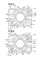
- a typical prior art such detent mechanism which includes a sheet spring, will now be explained with regard to Fig. 1 of the appended drawings, which is a view of a portion of the casing of the rotary switch in which said prior art sheet spring is housed, said sheet spring being shown in plan view.
- the reference numeral 14 denotes a portion of the casing of this prior art rotary switch
- the reference numeral 34 denotes a disk shaped rotor member which is rotably supported within said casing portion 14.
- the diameter of the rotor member 34 is greater than the diameter of that circular portion thereof which is visible in Fig. 1; and in fact that one of the end surfaces of this rotor member 34 which faces the viewer from the point of view of Fig. 1 is formed on its radially extreme circumferential portion - which is in fact hidden in the Fig. 1 view by the sheet spring member 10 to be described shortly - with wavy irregularities not shown in the figure.
- this rotor member 34 is rotated about its rotational axis which is perpendicular to the plane of the Fig. 1 drawing paper, by a mechanism not shown in the figure said rotor member 34 opens and/or closes various contacts to provide switching action.
- a detent mechanism is provided for the rotatory action of this rotor member 34, comprising a sheet spring member 10 which is shown in plan view in Fig. 1, in a position as fixed to a switch casing 14 of this prior art rotary switch and ready for being pressed (in the direction forward out of the drawing paper in Fig. 1) against the radially outer circumferential portion of the rotor member 34 and against the wavy irregularities formed on said rotor member outer circumferential portion.
- This sheet spring member 10 is formed with an approximately square external outline, with two circular openings 52 each of which is formed in one of two substantially flat portions denoted as "F", each of which substantially flat portions "F” including one of a diagonally opposing pair of corners of said square external outline and said openings 52 falling near said diagonally opposing pair of corners, and with an approximately circular internal outline which is substantially concentric with said square external outline.
- the three dimensional shape of said sheet spring member 10 is as follows: the diagonally opposed pair of portions "F" including one diagonally opposed pair of corners of the sheet spring member 10 are substantially flat and are not distorted substantially out of the plane of the drawing paper, except that each of them is formed with two very slight creases denoted as 15a1 and 15a2, and 15b1 and 15b2, which serve for slightly angling the two portions which constitute the major portion of the remainder of the sheet spring member 10 as a whole in the direction towards the viewer from the point of view of Fig.
- each of the other diagonally opposed pair of portions, denoted as 12a and 12b and including the other diagonally opposed pair of corners of the sheet spring member 10, is formed with three obtusely angled creases denoted as 13a1, 13a2, and 13a3 for the portion 12a and as 13b1, 13b2, and 13b3 for the portion 12b.
- the obtuse angles of the creases 13a1 and 13b1 face away from the viewer from the point of view of Fig. 1, while on the other hand the obtuse angles of the creases 13a2, 13a3, 13b2, and 13b3 face towards the viewer from the point of view of Fig. 1.
- each of these diagonally opposed portions 12a and 12b of the sheet spring member 10 is formed in a shallow V shape, with the apexes or points of these V shapes being constituted by the obtusely angled creases 13a1 and 13b1 and each being displaced in the direction forward from the drawing paper with respect to the remainder of its portion 12a or 12b from the point of view of Fig. 1.
- fixing pins 16a and 16b formed as projecting towards the viewer from the point of view of Fig.
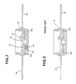
- FIG. 2 of the appended drawings which also relates to the prior art, and is a sectional view showing how in a typical conventional case terminals for electrical connection to the outside are led through the material of the casing of an electronic component by being insert molded thereinto.
- an eletronic component which is intended for being mounted to a printed circuit board comprises one or more terminals which extend from the interior of said electronic component to the outside thereof, typically passing through a casing of said electronic component, said casing typically being formed of a resin material such as a synthetic resin material.
- soldering flux type material It is very desirable, in fact it is essential, that this soldering flux should not be allowed to penetrate into the interior of the casing of the electronic component, during this soldering process.
- the terminal members such as 20 of the electronic component were insert molded into the body 18 of the electronic component during the manufacture of said electronic component body 18 from synthetic resin by a molding process, and accordingly inner portions such as 20a of said terminal members 20 were embedded in and were enclosed by synthetic resin, in the finished product.
- the close adhesion of the material of the electronic component body 18 to the inner terminal portions 20a was intended and desired to prevent the intrusive penetration of soldering flux into the interior of the casing of the electronic component during the process of soldering the terminal members 20 to a printed circuit pattern on a printed circuit base board.
- a rotary switch type electronic component comprising: (a) a casing; (b) a disk shaped rotor member, rotatably supported in said casing, and formed with a cam pattern system; (c) a contact system which is actuated by said cam pattern system formed on said disk shaped rotor member as said disk shaped rotor member is rotated; and: (d) a sheet spring, comprising: (d1) two pressure portions; (d2) a substantially flat portion, intermediate between said two pressure portions, which is stressed to as to press said two pressure portions against said cam pattern system formed on said disk shaped rotor member as said disk shaped rotor member is rotated, for providing detent action for said disk shaped rotor member; and: (d3) a fixing portion, fixed to said casing, and proximate and connected to said substantially flat portion.
- a rotary switch type electronic component comprising: (a) a casing; (b) a disk shaped rotor member, rotatably supported in said casing, and formed with a cam pattern system; (c) a contact system which is actuated by said cam pattern system formed on said disk shaped rotor memebr as said disk shaped rotor member is rotated; and: (d) a sheet spring, comprising: (d1) two pressure portions; (d2) two substantially flat portions, each intermediate between said two pressure portions, which are stressed so as to press said two pressure portions against said cam pattern system formed on said disk shaped rotor member as said disk shaped rotor member is rotated, for providing detent action for said disk shaped rotor member; and: (d3) two fixing portions, each fixed to said casing, and each proximate and connected to a corresponding one of said substantially flat portions.
- the construction may further be that the sheet spring is generally ring shaped with a generally circular interior outline and a generally square exterior outline, and said two pressure portions thereof are constituted by a pair of two diagonally opposed corner portions thereof which are creased so as to define projections opposing said cam pattern system formed on said disk shaped rotor member, while said two substantially flat portions thereof are constituted by the other pair of two diagonally opposed corner portions thereof which are creased so as to press said two pressure portions thereof against said cam pattern system formed on said disk shaped rotor member.
- the fixing portion or portions of said sheet spring may be connected to said substantially flat portion or portions thereof by a narrowed portion or portions; and a notch or notches may be defined on one side of said narrowed portion or portions of said sheet spring between said fixing portion or portions thereof and said substantially flat portion or portions thereof.
- the fixing portion or portions may be formed with an aperture or apertures by which it or they is or are fixed to the casing; and, in such a case, said fixing portion or portions may be fixed to said casing by thermal crimping, or by press fitting, or by snap fitting.
- the substantially flat portion or portions of the sheet spring need not to be used for fixing said sheet spring to the casing of the electronic component - since the fixing portions are used for that purpose - accordingly said substantially flat sheet spring portion or portions need not to be pierced with any apertures such as openings or the like, but instead may be left continuous, and thereby accordingly the stress set up in the sheet spring by distortion of said sheet spring during the performance of its springing action, which as explained earlier in this specification tends to be concentrated in said substantially flat sheet spring portion or portions, is much better able to be distributed, than was the case with the sheet spring formed according to the prior art as described earlier in this specification and as shown in Fig. 1.
- notch or notches as described above are provided between the sheet spring fixing portion or portions and its substantially flat portion or portions, because this notch or notches further isolates the stresss bearing function of said substantially flat portion or portions from the function of the fixing portions of fixing the sheet spring to the casing, thereby even less concentrated and more uniform and therefore overall greater stress bearing action is allowed to be provided by the substantially flat portion or portions.
- an electronic component comprising a resin casing and a terminal member passing through said resin casing between its inside and its outside, a hole being formed through said resin casing from a surface thereof to an interior point thereof which reaches said terminal member, and a quantity of thermosetting bonding agent being filled into said hole and sealing said terminal member to said casing.
- this electronic component is well and effectively sealed, and is not liable to lose its seal, even when its terminals are heated up as during soldering of said terminals to a printed circuit board. Further, this electronic component can maintain good performance without deterioration of its operational characteristics occurring due to the ingress of soldering flux, and is not liable to the occurrence of poor contact performance.
- Fig. 3 is an exploded perspective view showing the principal portions of the first preferred embodiment of the rotary switch type electronic component of the present invention.
- the reference numeral 14 denotes a cover member for this rotary switch
- the reference numeral 18 denotes a base member thereof.
- the switch cover member 14 is fitted securely to the switch base member 18, when the switch is assembled, with the other parts of the switch enclosed and held between them.
- this plurality of terminal members 20 which are embedded in and pass through the material of the switch base member 18, as will be more particularly described later, and exterior portions of which are projected to the outside of the rotary switch and are bent over, so as to be connected to a printed circuit board to which this rotary switch is to be fitted.
- Inner end portions, not particularly shown in this Fig. 3, of this plurality of terminal members 20 are connected to or, in this particular case, constitute a plurality of fixed contact members 22 which are exposed on the inner surface of the switch base member 18 at appropriate positions, as will be described hereinafter; these positions, in this particular preferred embodiment of the present invention, are arranged along a line.
- a circular depression or socket 32 which is for serving as a bearing hole.
- a contact plate 26 is formed in the general configuration of a comb, and the projections 30 thereof (there are in all four such projections 30, in the shown exemplary embodiment) are crinkled to and fro, so as to define upwardly projecting intermediate drive bumps 38 at their intermediate portions and movable contact portions 40 at their free ends which are bent round into upwardly opening letter "U" shapes. Further, two fixing apertures 28 are formed in said contact plate 26.
- the contact plate 26 is placed over the switch base member 18 with the fixing pins 24 of said switch base member 18 fitting into the fixing apertures 28 of said contact plate 26, and then the ends of the fixing pins 24 are crimped as for example by thermal crimping, so that the contact plate 26 is securely fitted in place over the switch base member 18.
- each of the movable contact portions 40 opposes an appropriate one of the fixed contact members 22, being, in the unstressed state of the contact plate 26 and of the projections 30, separated from said one of said fixed contact members 22 by a certain gap.
- the reference numeral 34 denotes a disk shaped rotor member which is rotatably supported between the switch cover member 14 and the switch base member 18.
- the lower surface of this rotor member 34 from the point of view of Fig. 3 is formed on its radially outer circumferential portion - only slightly visible in the Fig. 3 view - with a wavy irregular pattern denoted as 36 but not clearly or completely shown in the figures. Further, at the center of this lower surface of this rotor member 34 from the point of view of Fig. 3 there is provided a stub shaft, not shown in the figures.
- stub shaft thereof is rotatably fitted into the bearing hole socket 32 formed as described above on the inner surface of the switch base member 18, and then as the switch cover member 14 is fitted over said switch base member 18 the raised disk portion 8 of said rotor member 34 is rotatably fitted into a correspondingly shaped and sized circular aperture 46 formed in said switch cover member 14, with the interposition of a sealing O ring denoted as 45; thereby, the rotor member 34 is rotatably supported within the body of the rotary switch, and can conveniently be turned about its central axis by a user fitting the tip of a screwdriver into the slot 42 and turning said screwdriver.
- This detent mechanism comprises a sheet spring member 10 which is sandwiched between the upper face from the point of view of Fig. 3 of the rotor member 34 and the lower surface of the switch cover member 14.
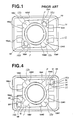
- This sheet spring member 10 is shown in perspective view in Fig. 3, while being shown in plan view in Fig. 4, from the point of view of which figure it lies in front of the radially outer circumferential portion of the rotor member 34 and hides the wavy irregularities 44 formed on the outer circumferential portion of said rotor member 34.
- This sheet spring member 10 is formed with an approximately square external outline, except that, from each of two substantially flat portions denoted as "F" each of which includes one of a diagonally opposing pair of corners of said square external outline, there extends a mounting ear portion denoted as 48, connected to the main body of the sheet spring member 10 by a narrow connecting bridge portion denoted as 51, on the one side of which there is defined a notch shape 50.
- Each of these mounting ear portions 48 is formed with a circular opening 52.
- the sheet spring member 10 is formed with an approximately circular internal outline which is substantially concentric with its general square external outline, and which fits over the raised disk portion 8 of the rotor member 34. Further, the three dimensional shape of this sheet spring member 10, not particularly shown in Fig.
- the diagonally opposed pair of portions "F" thereof including one diagonally opposed pair of corners of the sheet spring member 10 are substantially flat and are not distorted substantially out of the plane of the drawing paper of Fig. 4, except that each of them is formed with two very slight creases denoted as 15a1 and 15a2, and 15b1 and 15b2, which serve for slightly angling the two portions which constitute the major portion of the remainder of the sheet spring member 10 as a whole in the direction towards the viewer from the point of view of Fig.
- each of the other diagonally opposed pair of portions, denoted as 12a and 12b and including the other diagonally opposed pair of corners of the sheet spring member 10, is formed with three obtusely angled creases denoted as 13a1, 13a2, and 13a3 for the portion 12a and as 13b1, 13b2, and 13b3 for the portion 12b.
- the obtuse angles of the creases 13a1 and 13b1 face away from the viewer from the point of view of Fig. 4, while on the other hand the obtuse angles of the creases 13a2, 13a3, 13b2, and 13b3 face towards the viewer from the point of view of Fig. 4.
- each of these diagonally opposed portions 12a and 12b of the sheet spring member 10 is formed in a shallow V shape, with the apexes or points of these V shapes being constituted by the obtusely angled creases 13a1 and 13b1 and each being displaced in the direction forward from the drawing paper with respect to the remainder of its portion 12a or 12b from the point of view of Fig. 4 and in the direction pointing downwards from the point of view of Fig. 3.
- the openings 52 formed in the mounting ear portions 48 there are passed fixing pins 16a and 16b formed as projecting towards the viewer from the point of view of Fig. 4 on the lower surface as seen in Fig.
- this construction according to this first preferred embodiment of the rotary switch type electronic component of the present invention does not entail any particularly severe cost or weight or bulk penalties.
- a further benefit of the shown first preferred embodiment construction is attained by the provision of the notches 50 which are present between the mounting gear portions 48 and the diagonally opposed portions "F" of the sheet spring member 10, because this further isolates the stress bearing function of said diagonally opposed portions "F” from the function of said mounting ear portions 48 of fixing the sheet spring member 10 to the switch cover member 14, thereby further allowing less concentrated and more uniform and therefore overall greater stress bearing action to be provided by said diagonally opposed portions "F".
- Fig. 7 is a sectional view of the switch base member 18 of this first preferred embodiment of the rotary switch type electronic component of the present invention, taken in a plane shown by the arrows VII - VII in Fig. 3, and is similar to Fig. 2 described above with reference to the prior art. It should be understood that the switch base member 18 and the switch cover member 14 are, in this first preferred embodiment, both formed from synthetic resin.
- terminal members 20 are embedded in and pass through the material of the switch base member 18, and their exterior portions are projected to the outside of the rotary switch and are bent over, so as to be connected to a printed circuit board, not particularly shown, to which this rotary switch is to be fitted, while, in this construction, the inner end portions of the terminal members 20 constitute the fixed contact members 22, previously described.
- thermosetting bonding agent sealing plugs 62 are in fact utilized, corresponding to several of the terminal members 20; and, desirably, each of said terminal members 20 is provided with such a thermosetting bonding agent sealing plug 62 fitted into an appropriate such hole 60 which reaches from the outside to said terminal member 20 - however, according to the Fig.
- thermosetting bonding agent sealing plug 62 may be single liquid type thermosetting epoxy resin.
- thermosetting bonding agent sealing plug 62 sets hard and thus effectively seals between the terminal member 20 and the switch base member 18.
- solder typically a solder is used, and the temperature of this solder bath may typically be about 260°C or so.
- the soldering process typically takes about 10 seconds for completion, and typically raises the temperatures of the portions of the terminal members 20 which are exposed outside the casing of the electronic component to about 210°C or so, while typically raising the temperatures of the internally exposed fixed contact members 22 to about 180°C or so.
- these terminal members 20 and also the proximate portions to said terminal members 20 of the material of the electronic component body 18 are considerably heated up during the above described soldering process.
- this electronic component is well and effectively sealed, and is not liable to lose its seal, even when its terminals are heated up as during soldering of said teminals to a printed circuit board. Further, this electronic component can maintain good performance without deterioration of its operational characteristics occurring due to the ingress of soldering flux, and is not liable to the occurrence of poor contact performance.
- This second preferred embodiment differs from the first preferred embodiment described above, only in that the sheet spring member 10 is attached by the fixing pins 16a and 16b to the switch cover member 14, not by the use of thermal crimping as was the case in said first preferred embodiment, but by press fitting of said fixing pins 16a and 16b into the openings 52 of the mounting ear portions 48. Otherwise the construction is the same as in the first preferred embodiment, and accordingly the same advantages and benefits accrue as in this case of said first preferred embodiment.
- This third preferred embodiment differs from the first and the second preferred embodiments described above, only in that the sheet spring member 10 is attached by the fixing pins 16a and 16b to the switch cover member 14, not by the use of thermal crimping as was the case in said first preferred embodiment or by press fitting as was the case in said second preferred embodiment, but by snap fitting of the fixing pins 16a and 16b into the openings 52 of the mounting ear portions 48. Otherwise the construction is the same as in the first and the second preferred embodiments, and accordingly the same advantages and benefits accrue as in this case of said first and second preferred embodiments.
Landscapes
- Physics & Mathematics (AREA)
- Electromagnetism (AREA)
- Rotary Switch, Piano Key Switch, And Lever Switch (AREA)
- Switches With Compound Operations (AREA)
Priority Applications (1)
| Application Number | Priority Date | Filing Date | Title |
|---|---|---|---|
| AT87114682T ATE100966T1 (de) | 1986-10-08 | 1987-10-08 | Elektronisches bauelement mit drehschalterrastfeder. |
Applications Claiming Priority (4)
| Application Number | Priority Date | Filing Date | Title |
|---|---|---|---|
| JP15451886U JPS6360230U (de) | 1986-10-08 | 1986-10-08 | |
| JP154518/86U | 1986-10-08 | ||
| JP171134/86U | 1986-11-07 | ||
| JP17113486U JPS6377224U (de) | 1986-11-07 | 1986-11-07 |
Publications (3)
| Publication Number | Publication Date |
|---|---|
| EP0265732A2 true EP0265732A2 (de) | 1988-05-04 |
| EP0265732A3 EP0265732A3 (en) | 1988-09-28 |
| EP0265732B1 EP0265732B1 (de) | 1994-01-26 |
Family
ID=26482783
Family Applications (1)
| Application Number | Title | Priority Date | Filing Date |
|---|---|---|---|
| EP87114682A Expired - Lifetime EP0265732B1 (de) | 1986-10-08 | 1987-10-08 | Elektronisches Bauelement mit Drehschalterrastfeder |
Country Status (3)
| Country | Link |
|---|---|
| US (1) | US4855541A (de) |
| EP (1) | EP0265732B1 (de) |
| DE (1) | DE3788927T2 (de) |
Cited By (2)
| Publication number | Priority date | Publication date | Assignee | Title |
|---|---|---|---|---|
| DE4328030A1 (de) * | 1993-08-20 | 1995-02-23 | Marquardt Gmbh | Elektrischer Schalter |
| EP0747630A3 (de) * | 1995-06-06 | 1997-03-26 | Eaton Corp | Gedichteter Schalter zur Verwendung mit einem drehbaren Ventilschaft |
Families Citing this family (14)
| Publication number | Priority date | Publication date | Assignee | Title |
|---|---|---|---|---|
| US5010214A (en) * | 1988-08-11 | 1991-04-23 | Atsuo Yamazaki | Rotary switch |
| DK140892D0 (da) * | 1992-11-24 | 1992-11-24 | Lego As | Elektrisk omskifter |
| US5539165A (en) * | 1994-11-02 | 1996-07-23 | Wu; John | Electric lock for children's automobiles |
| JP4013388B2 (ja) * | 1999-03-09 | 2007-11-28 | 松下電器産業株式会社 | 複合スイッチ |
| JP3860382B2 (ja) * | 2000-03-01 | 2006-12-20 | アルプス電気株式会社 | 回転型電気部品 |
| JP4005766B2 (ja) * | 2000-09-28 | 2007-11-14 | アルプス電気株式会社 | スイッチ装置 |
| JP4720515B2 (ja) * | 2006-01-18 | 2011-07-13 | パナソニック株式会社 | 回転操作型電子部品 |
| US20090272207A1 (en) * | 2008-05-01 | 2009-11-05 | Thomas John Buckingham | Rotary actuating mechanism having selectable rotary wheels |
| DE102009037016A1 (de) | 2009-08-07 | 2011-02-24 | Carl Zeiss Surgical Gmbh | Drehschalter und Gerät, insbesondere medizinisches Gerät und/oder optisches Beobachtungsgerät |
| JP5446801B2 (ja) * | 2009-12-07 | 2014-03-19 | パナソニック株式会社 | 回転型電子部品 |
| JP4755718B2 (ja) * | 2010-02-03 | 2011-08-24 | 東京コスモス電機株式会社 | 電気部品のクリック機構 |
| CN102709092A (zh) * | 2012-06-14 | 2012-10-03 | 宁波永佳电子科技有限公司 | 一种汽车空调模式开关 |
| CN104715954B (zh) * | 2013-12-16 | 2019-01-25 | 博西华电器(江苏)有限公司 | 家用电器的旋钮式操作装置及家用电器 |
| CN211294934U (zh) * | 2019-12-05 | 2020-08-18 | 通力股份公司 | 用于凸轮开关的具有一体化结构的固定触头和凸轮开关 |
Family Cites Families (11)
| Publication number | Priority date | Publication date | Assignee | Title |
|---|---|---|---|---|
| DE6812711U (de) * | 1968-12-21 | 1969-09-18 | Sel Kontakt Bauelemente G M B | Drehschalter mit rasteinrichtung |
| US3668299A (en) * | 1971-04-29 | 1972-06-06 | Beckman Instruments Inc | Electrical circuit module and method of assembly |
| DE2302453C3 (de) * | 1973-01-18 | 1979-01-11 | Ebe Elektro-Bau-Elemente Gmbh, 7022 Leinfelden-Echterdingen | Rastwerk für einen Stufendrehschalter |
| JPS6020258Y2 (ja) * | 1977-09-29 | 1985-06-18 | 株式会社デルフアイ | Dip型ロ−タリ−スイツチ |
| DE8124847U1 (de) * | 1981-08-26 | 1983-03-10 | Siemens AG, 1000 Berlin und 8000 München | Elektrisches Bauelement mit einem mehrteiligen, mit Gießharz abgedichteten Gehäuse |
| US4400597A (en) * | 1982-02-16 | 1983-08-23 | Eeco Incorporated | Axial cam rotary switch |
| DE3225694C2 (de) * | 1982-07-09 | 1985-02-07 | Standard Elektrik Lorenz Ag, 7000 Stuttgart | Drehschalteraufsatz |
| JPS5957821U (ja) * | 1982-10-08 | 1984-04-16 | アルプス電気株式会社 | ロ−タリ−パルススイツチ |
| JPS59110930U (ja) * | 1983-01-16 | 1984-07-26 | 日本開閉器工業株式会社 | 小型ロ−タリ−スイツチ |
| JPS59217914A (ja) * | 1983-05-25 | 1984-12-08 | オータックス株式会社 | 電子回路を内蔵したスイツチ |
| DE3527339A1 (de) * | 1984-06-28 | 1986-01-02 | Alps Electric Co., Ltd., Tokio/Tokyo | Elektronisches bauteil |
-
1987
- 1987-10-08 EP EP87114682A patent/EP0265732B1/de not_active Expired - Lifetime
- 1987-10-08 DE DE3788927T patent/DE3788927T2/de not_active Expired - Lifetime
- 1987-10-08 US US07/105,791 patent/US4855541A/en not_active Expired - Lifetime
Cited By (3)
| Publication number | Priority date | Publication date | Assignee | Title |
|---|---|---|---|---|
| DE4328030A1 (de) * | 1993-08-20 | 1995-02-23 | Marquardt Gmbh | Elektrischer Schalter |
| DE4328030C2 (de) * | 1993-08-20 | 2002-08-14 | Marquardt Gmbh | Elektrischer Drehschalter |
| EP0747630A3 (de) * | 1995-06-06 | 1997-03-26 | Eaton Corp | Gedichteter Schalter zur Verwendung mit einem drehbaren Ventilschaft |
Also Published As
| Publication number | Publication date |
|---|---|
| US4855541A (en) | 1989-08-08 |
| EP0265732B1 (de) | 1994-01-26 |
| EP0265732A3 (en) | 1988-09-28 |
| DE3788927D1 (de) | 1994-03-10 |
| DE3788927T2 (de) | 1994-09-01 |
Similar Documents
| Publication | Publication Date | Title |
|---|---|---|
| EP0265732A2 (de) | Elektronisches Bauelement mit Drehschalterrastfeder | |
| CA1120613A (en) | Transducer arrangement with integral terminals | |
| JP3498429B2 (ja) | プッシュスイッチ | |
| US3978298A (en) | Miniature switch having pivotal actuator with budging contact and position safety structure | |
| JP4563470B2 (ja) | 回転型電気部品 | |
| US6486427B1 (en) | Electrical switch | |
| GB2077041A (en) | Electrical switch | |
| JPH11312442A (ja) | 多方向スイッチおよびこの多方向スイッチを用いた電子機器 | |
| JP2002352664A (ja) | プッシュスイッチ | |
| EP0940822B1 (de) | Veränderbarer Widerstand | |
| JP4058892B2 (ja) | プッシュスイッチ | |
| JP3367787B2 (ja) | 可変抵抗器 | |
| JPH11345706A (ja) | 回転操作型可変抵抗器およびその製造方法 | |
| JP3346106B2 (ja) | プッシュスイッチ | |
| US4208646A (en) | Thermally responsive electric switch | |
| JP2725209B2 (ja) | 回転形スイツチ | |
| US4020445A (en) | Variable resistance control | |
| JP3338305B2 (ja) | 回転型可変抵抗器 | |
| JPH0128592Y2 (de) | ||
| JPH0228565Y2 (de) | ||
| JPH0539540Y2 (de) | ||
| JPH0416402Y2 (de) | ||
| JP2530507Y2 (ja) | カード用コネクタ | |
| JP2590290Y2 (ja) | プリント基板用小形スイッチ | |
| JP2529022Y2 (ja) | ロ−タリスイッチ |
Legal Events
| Date | Code | Title | Description |
|---|---|---|---|
| PUAI | Public reference made under article 153(3) epc to a published international application that has entered the european phase |
Free format text: ORIGINAL CODE: 0009012 |
|
| 17P | Request for examination filed |
Effective date: 19871008 |
|
| AK | Designated contracting states |
Kind code of ref document: A2 Designated state(s): AT BE CH DE ES FR GB GR IT LI LU NL SE |
|
| PUAL | Search report despatched |
Free format text: ORIGINAL CODE: 0009013 |
|
| AK | Designated contracting states |
Kind code of ref document: A3 Designated state(s): AT BE CH DE ES FR GB GR IT LI LU NL SE |
|
| 17Q | First examination report despatched |
Effective date: 19910703 |
|
| GRAA | (expected) grant |
Free format text: ORIGINAL CODE: 0009210 |
|
| AK | Designated contracting states |
Kind code of ref document: B1 Designated state(s): AT BE CH DE ES FR GB GR IT LI LU NL SE |
|
| PG25 | Lapsed in a contracting state [announced via postgrant information from national office to epo] |
Ref country code: IT Free format text: LAPSE BECAUSE OF FAILURE TO SUBMIT A TRANSLATION OF THE DESCRIPTION OR TO PAY THE FEE WITHIN THE PRE;WARNING: LAPSES OF ITALIAN PATENTS WITH EFFECTIVE DATE BEFORE 2007 MAY HAVE OCCURRED AT ANY TIME BEFORE 2007. THE CORRECT EFFECTIVE DATE MAY BE DIFFERENT FROM THE ONE RECORDED.SCRIBED TIME-LIMIT Effective date: 19940126 Ref country code: LI Effective date: 19940126 Ref country code: GR Free format text: LAPSE BECAUSE OF FAILURE TO SUBMIT A TRANSLATION OF THE DESCRIPTION OR TO PAY THE FEE WITHIN THE PRESCRIBED TIME-LIMIT Effective date: 19940126 Ref country code: SE Effective date: 19940126 Ref country code: CH Effective date: 19940126 Ref country code: BE Effective date: 19940126 Ref country code: NL Effective date: 19940126 Ref country code: AT Effective date: 19940126 |
|
| REF | Corresponds to: |
Ref document number: 100966 Country of ref document: AT Date of ref document: 19940215 Kind code of ref document: T |
|
| REF | Corresponds to: |
Ref document number: 3788927 Country of ref document: DE Date of ref document: 19940310 |
|
| ET | Fr: translation filed | ||
| REG | Reference to a national code |
Ref country code: CH Ref legal event code: PL |
|
| PG25 | Lapsed in a contracting state [announced via postgrant information from national office to epo] |
Ref country code: ES Free format text: LAPSE BECAUSE OF FAILURE TO SUBMIT A TRANSLATION OF THE DESCRIPTION OR TO PAY THE FEE WITHIN THE PRESCRIBED TIME-LIMIT Effective date: 19940507 |
|
| NLV1 | Nl: lapsed or annulled due to failure to fulfill the requirements of art. 29p and 29m of the patents act | ||
| PG25 | Lapsed in a contracting state [announced via postgrant information from national office to epo] |
Ref country code: LU Free format text: LAPSE BECAUSE OF NON-PAYMENT OF DUE FEES Effective date: 19941031 |
|
| PLBE | No opposition filed within time limit |
Free format text: ORIGINAL CODE: 0009261 |
|
| STAA | Information on the status of an ep patent application or granted ep patent |
Free format text: STATUS: NO OPPOSITION FILED WITHIN TIME LIMIT |
|
| 26N | No opposition filed | ||
| REG | Reference to a national code |
Ref country code: GB Ref legal event code: 746 Effective date: 19980930 |
|
| REG | Reference to a national code |
Ref country code: FR Ref legal event code: D6 |
|
| REG | Reference to a national code |
Ref country code: GB Ref legal event code: IF02 |
|
| PG25 | Lapsed in a contracting state [announced via postgrant information from national office to epo] |
Ref country code: FR Free format text: LAPSE BECAUSE OF NON-PAYMENT OF DUE FEES Effective date: 20060630 |
|
| PGFP | Annual fee paid to national office [announced via postgrant information from national office to epo] |
Ref country code: GB Payment date: 20061016 Year of fee payment: 20 |
|
| REG | Reference to a national code |
Ref country code: FR Ref legal event code: ST Effective date: 20060630 |
|
| PGFP | Annual fee paid to national office [announced via postgrant information from national office to epo] |
Ref country code: DE Payment date: 20061031 Year of fee payment: 20 |
|
| REG | Reference to a national code |
Ref country code: FR Ref legal event code: D3 |
|
| REG | Reference to a national code |
Ref country code: GB Ref legal event code: PE20 |
|
| PG25 | Lapsed in a contracting state [announced via postgrant information from national office to epo] |
Ref country code: GB Free format text: LAPSE BECAUSE OF EXPIRATION OF PROTECTION Effective date: 20071007 |
|
| PGFP | Annual fee paid to national office [announced via postgrant information from national office to epo] |
Ref country code: FR Payment date: 20061018 Year of fee payment: 20 |