EP0265737A1 - Lichtleiteranordnung bei einem Hochspannungsisolator - Google Patents
Lichtleiteranordnung bei einem Hochspannungsisolator Download PDFInfo
- Publication number
- EP0265737A1 EP0265737A1 EP87114723A EP87114723A EP0265737A1 EP 0265737 A1 EP0265737 A1 EP 0265737A1 EP 87114723 A EP87114723 A EP 87114723A EP 87114723 A EP87114723 A EP 87114723A EP 0265737 A1 EP0265737 A1 EP 0265737A1
- Authority
- EP
- European Patent Office
- Prior art keywords
- light guide
- insulator
- silicone
- voltage
- helix
- Prior art date
- Legal status (The legal status is an assumption and is not a legal conclusion. Google has not performed a legal analysis and makes no representation as to the accuracy of the status listed.)
- Granted
Links
- 239000012212 insulator Substances 0.000 title claims abstract description 81
- 239000013307 optical fiber Substances 0.000 title abstract description 17
- 229920001296 polysiloxane Polymers 0.000 claims abstract description 43
- 239000011152 fibreglass Substances 0.000 claims abstract description 9
- 239000013013 elastic material Substances 0.000 claims 1
- 239000004033 plastic Substances 0.000 abstract description 2
- 229920003023 plastic Polymers 0.000 abstract description 2
- 238000005259 measurement Methods 0.000 abstract 1
- 229910018503 SF6 Inorganic materials 0.000 description 4
- SFZCNBIFKDRMGX-UHFFFAOYSA-N sulfur hexafluoride Chemical compound FS(F)(F)(F)(F)F SFZCNBIFKDRMGX-UHFFFAOYSA-N 0.000 description 4
- 238000004804 winding Methods 0.000 description 4
- 230000008878 coupling Effects 0.000 description 3
- 238000010168 coupling process Methods 0.000 description 3
- 238000005859 coupling reaction Methods 0.000 description 3
- 239000000835 fiber Substances 0.000 description 3
- 238000004519 manufacturing process Methods 0.000 description 3
- IJGRMHOSHXDMSA-UHFFFAOYSA-N Atomic nitrogen Chemical compound N#N IJGRMHOSHXDMSA-UHFFFAOYSA-N 0.000 description 2
- 230000005540 biological transmission Effects 0.000 description 2
- 230000000694 effects Effects 0.000 description 2
- 239000007789 gas Substances 0.000 description 2
- 239000003365 glass fiber Substances 0.000 description 2
- 229960000909 sulfur hexafluoride Drugs 0.000 description 2
- 230000007704 transition Effects 0.000 description 2
- 239000000919 ceramic Substances 0.000 description 1
- 239000003795 chemical substances by application Substances 0.000 description 1
- 239000012777 electrically insulating material Substances 0.000 description 1
- 239000006260 foam Substances 0.000 description 1
- 239000000463 material Substances 0.000 description 1
- 229910052757 nitrogen Inorganic materials 0.000 description 1
- 230000003287 optical effect Effects 0.000 description 1
- 238000007789 sealing Methods 0.000 description 1
- 238000007669 thermal treatment Methods 0.000 description 1
Images

Classifications
-
- H—ELECTRICITY
- H01—ELECTRIC ELEMENTS
- H01B—CABLES; CONDUCTORS; INSULATORS; SELECTION OF MATERIALS FOR THEIR CONDUCTIVE, INSULATING OR DIELECTRIC PROPERTIES
- H01B17/00—Insulators or insulating bodies characterised by their form
- H01B17/005—Insulators structurally associated with built-in electrical equipment
-
- G—PHYSICS
- G02—OPTICS
- G02B—OPTICAL ELEMENTS, SYSTEMS OR APPARATUS
- G02B6/00—Light guides; Structural details of arrangements comprising light guides and other optical elements, e.g. couplings
- G02B6/44—Mechanical structures for providing tensile strength and external protection for fibres, e.g. optical transmission cables
- G02B6/4401—Optical cables
- G02B6/4415—Cables for special applications
- G02B6/4416—Heterogeneous cables
- G02B6/4417—High voltage aspects, e.g. in cladding
- G02B6/442—Insulators
-
- G—PHYSICS
- G02—OPTICS
- G02B—OPTICAL ELEMENTS, SYSTEMS OR APPARATUS
- G02B6/00—Light guides; Structural details of arrangements comprising light guides and other optical elements, e.g. couplings
- G02B6/44—Mechanical structures for providing tensile strength and external protection for fibres, e.g. optical transmission cables
- G02B6/4401—Optical cables
- G02B6/4415—Cables for special applications
- G02B6/4416—Heterogeneous cables
- G02B6/4417—High voltage aspects, e.g. in cladding
- G02B6/442—Insulators
- G02B6/4421—Insulators with helical structure of optical fibre, e.g. fibres wound around insulators
-
- H—ELECTRICITY
- H01—ELECTRIC ELEMENTS
- H01H—ELECTRIC SWITCHES; RELAYS; SELECTORS; EMERGENCY PROTECTIVE DEVICES
- H01H33/00—High-tension or heavy-current switches with arc-extinguishing or arc-preventing means
- H01H33/02—Details
- H01H33/42—Driving mechanisms
- H01H33/423—Driving mechanisms making use of an electromagnetic wave communication
Definitions
- the invention is based on an optical fiber arrangement in a high-voltage insulator according to the preamble of patent claim 1.
- the invention relates to a prior art of light guide arrangements in a high-voltage insulator, as is known from DE-A1-34 26 536.
- There optical fibers are mechanically protected, rectilinear and uncoiled on a circular cylindrical support element with an electrically limited conductive surface.
- the carrier element is fixedly arranged on an insulator column filled with an insulating agent.
- the optical fibers are hermetically sealed through the insulator column.
- a winding of the optical waveguide is considered disadvantageous there for mechanical and transmission reasons.
- the invention solves the problem of specifying a light guide arrangement in a high voltage insulator, in which the voltage gradient along the light guide between the high voltage side and the earth potential side of the high voltage insulator is reduced.
- An advantage of the invention is that the usually lower dielectric strength of the light guide compared to that of the high-voltage insulator is compensated for by the longer length of the light guide.
- attenuation losses in the transmission path through the high-voltage insulator are negligible.
- the advantage of a longer surface creep path is that the voltage gradient is reduced more.
- An advantage of the helix according to claim 3 is that its end terminations can perform several functions.
- a light guide with a light guide plug that is sufficiently long for the high-voltage module can be accommodated in the upper end or end closure container.
- Couplings for the fiber optic output of the high-voltage module can be attached in the lower end or terminal box.
- the recess or groove in the helix according to claim 4 and the hollow helix according to claim 5 ensure a good and stable position of the light guide.
- An advantage of embedding the light guide in the insulator tube is that this takes place during the manufacture of the insulator tube, so that the light guide is guided in a spiral in one of the upper layers of the insulator tube from one end of the insulator tube to the other.
- Embedding the light guide in an additional silicone layer on the insulator tube according to claim 8 has the advantage that the supporting cross section of the insulator tube is not reduced.
- An advantage of the light guide recess in the silicone layer according to claim 9 is that the light guide can be retracted.
- the light guide recess on the underside of the silicone screen according to claim 10 allows easy pressing in of the light guide with a self-holding effect after completion of the high-voltage insulator.
- the configurations of the invention according to claims 7 to 10 have the common advantage that the light guide does not come into contact with the medium (oil, sulfur hexafluoride SF6, foam) present in the interior of the high-voltage insulator.
- the axial stress can be controlled by the slope of the winding spiral. There are no transitions into the interior of the high-voltage insulator due to optical fibers, which could raise sealing problems.
- the light guide is protected against external influences such as moisture and mechanical damage by the glass fiber reinforced plastic and silicone layer.
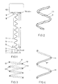
- Fig. 1 denotes a vertical, tubular, air-filled or ventilated high-voltage insulator made of ceramic or glass fiber-reinforced plastic, which stands on a base 2 with a base plate 1 in the open via a metallic ground flange 5 which is at ground potential.
- the high-voltage insulator 6 is closed off by a metallic high-voltage flange 9, which carries a high-voltage module 10, preferably a converter head housing with a current transformer.
- a self-supporting coil 7 made of an electrically well-insulating plastic, which is supported at the bottom on a terminal box 3 with optical fiber couplings 4.
- an end closure container 8 is provided for fastening the helix to the high-voltage insulator 6 and for receiving an optical fiber or optical fiber cable with a plurality of optical fibers.
- light guide connectors are mounted for coupling the light guide to electronics (not shown) of the high-voltage module 10.
- the helix 7 has no vertical supports.
- the helix 7 can have a circular cross section.
- the length of the light guide 11 within a height h of the high-voltage insulator 6 is preferably equal to 10 ⁇ h.
- the light guide 11 transmits information generated by the high-voltage module 10 in the form of light pulses into a protected measuring room (not shown) at earth potential, or commands in the opposite direction.
- a helix 7 ⁇ with a U-shaped profile 12 can also be used, as indicated in FIG. 3.
- the light guide 11 is placed in the longitudinal groove of this U-shaped profile 12.
- a tubular helix 7 ⁇ can also be used, cf. Fig. 4, in which the light guide 11 can be drawn.
- the tube of the coil 7 ⁇ should not be hermetically sealed in order to ensure a medium exchange (gas, air) between the interior of the high-voltage insulator 6 and the cavity of the coil 7 ⁇ .
- the filaments 7 and 7 ⁇ , 7 ⁇ with terminal box 5 and end closure container 8 form a separate structural unit which is mounted in the finished high-voltage insulator 6.
- the high-voltage insulator 6 can thus consist of several prefabricated sections with intermediate flanges, not shown, without problems of continuity of the light guide.
- a filament 7 or 7 ⁇ , 7 ⁇ made of a flexible material it is possible to pull a universal light guide to the desired length of the filament.
- the high-voltage insulator 6 if required, also hermetically sealed and with an insulating gas such as Nitrogen or sulfur hexafluoride SF6, can be filled.
- the bottom flange 5 closes hermetically with the terminal box 3 and the high-voltage flange 9 with the end closure container 8.
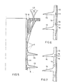
- FIG. 5 shows a section of a high-voltage insulator 6 according to FIG. 1 with an insulator tube 13 made of glass fiber-reinforced plastic, in the outer layer of which 2 light guides 11 are embedded in a spiral during the manufacture of the insulator tube and are guided from one end to the other of the insulator tube.
- the exit points of the light guides 11 lead outwards close to the lower or upper or high-voltage flange 9.
- the free ends of the light guides 11 are preferably protected by electrically insulating relief hoses 19 through openings in the lower or upper flange 9 and provided at the end with light guide plugs, not shown.
- the short transition of the light guide 11 from the insulator tube 13 into the flange 9 is covered when the insulator tube 13 is shielded with a silicone layer 14 which has silicone shields 15 for extending a surface creep path k indicated by dashed lines.
- optical fiber cables 16 with optical fibers 11 located therein are either spirally wound on the outside of the insulator tube 13 and then embedded in the poured-on silicone layer 14 (FIG. 6) or fully enveloped by the silicone layer 14 (FIG. 7) .
- optical fiber cables 16 with optical fibers 11 are embedded in an endless silicone shielding tape 14, which is wound spirally onto the insulator tube 13 in such a way that the optical fiber cable either rests against the insulator tube 13 (FIG. 8) or from Silicone is fully encased (Fig. 9).
- the silicone screen band 14 ⁇ has a width b and a silicone screen 15.
- two light guide cables 16 with light guides 11 are subsequently drawn into a recess 17 in the silicone shield band 14 ', adjacent to the surface of the insulator tube 13.
- an optical fiber cable 16 having an optical fiber 11 is pressed into a recess 18 on the underside of the silicone screen 15 after winding up the silicone screen band 14 ', in which it is held by the self-holding effect.
- the light guide is very well defined and reproducible.
- the axial stress can be controlled by the slope of the winding spiral.
- the less well-defined geometry of the light guide in the vicinity of the flanges 5 and 9 is already in a zone in which the voltage gradient has been reduced to a low value by external control electrodes. Due to the spiral guide, the light guide 11 is only subjected to very little mechanical stress even in the case of strong bends in the insulator.
- the light guide 11 is not exposed to high temperatures during production-related thermal treatments of the insulator tube 13, the light guide 11 can be replaced, - You can pull in an additional light guide 11, the light guide 11 is even better protected in the tube, the space around the light guide 11 can be ventilated, - The light guide is not exposed to mechanical stresses.
Landscapes
- Physics & Mathematics (AREA)
- General Physics & Mathematics (AREA)
- Optics & Photonics (AREA)
- Electromagnetism (AREA)
- Insulators (AREA)
- Light Guides In General And Applications Therefor (AREA)
- Optical Couplings Of Light Guides (AREA)
Abstract
Description
- Bei der Erfindung wird ausgegangen von einer Lichtleiteranordnung bei einem Hochspannungsisolator nach dem Oberbegriff des Patentanspruchs 1.
- Mit dem Oberbegriff nimmt die Erfindung auf einen Stand der Technik von Lichtleiteranordnungen bei einem Hochspannungsisolator Bezug, wie er aus der DE-A1-34 26 536 bekannt ist. Dort werden Lichtwellenleiter mechanisch geschützt, gradlinig und ungewendelt an einem kreiszylindrischen Trägerelement mit elektrisch begrenzt leitfähiger Oberfläche fixiert. Das Trägerelement ist fest an einer mit einem Isoliermittel gefüllten Isolatorsäule angeordnet. Die Lichtwellenleiter sind hermetisch dicht durch die Isolatorsäule geführt. Eine Wendelung des Lichtwellenleiters wird dort aus mechanischen und übertragungstechnischen Gründen als nachteilig angesehen.
- Die Erfindung, wie sie im Patentanspruch 1 definiert ist, löst die Aufgabe, eine Lichtleiteranordnung bei einem Hochspannungsisolator anzugeben, bei welcher der Spannungsgradient längs des Lichtleiters zwischen der Hochspannungsseite und der Erdpotentialseite des Hochspannungsisolators verringert ist.
- Ein Vorteil der Erfindung besteht darin, dass die üblicherweise geringere Spannungsfestigkeit des Lichtleiters im Vergleich zu der des Hochspannungsisolators durch die grössere Länge des Lichtleiters kompensiert wird. Bei Verwendung von Glasfasern für die Lichtleiter sind Dämpfungsverluste im Uebertragungsweg durch den Hochspannungsisolator vernachlässigbar.
- Der Vorteil eines längeren Oberflächenkriechweges gemäss Anspruch 2 besteht darin, dass der Spannungsgradient stärker reduziert ist.
- Ein Vorteil der Wendel gemäss Anspruch 3 besteht darin, dass deren endseitige Abschlüsse mehrere Funktionen erfüllen können. Im oberen Abschluss bzw. Endverschlussbehälter kann ein für die hochspannungführende Baugruppe ausreichend langer Lichtleiter mit Lichtleiterstecker untergebracht werden. Im unteren Abschluss bzw. Klemmkasten können Kopplungen für den faseroptischen Ausgang der hochspannungführenden Baugruppe angebracht sein.
- Die Aussparung bzw. Rille in der Wendel gemäss Anspruch 4 und die hohle Wendel gemäss Anspruch 5 gewährleisten eine gute und lagestabile Führung des Lichtleiters.
- Bei Verwendung eines flexiblen Rohres als Wendel gemäss Anspruch 6 besteht die Möglichkeit, eine universelle Lichtleiterführung auf die gewünschte Länge der Wendel zu ziehen. Eine selbsttragende Wendel ohne vertikale Abstützungen hat bei belüftetem Hochspannungsisolator den Vorteil einer grösseren Ueberschlagsfestigkeit.
- Ein Vorteil der Einbettung des Lichtleiters im Isolatorrohr gemäss Anspruch 7 besteht darin, dass dies bei der Herstellung des Isolatorrohres geschieht, so dass der Lichtleiter in einer der oberen Schichten des Isolatorrohres spiralförmig von einem zum anderen Ende des Isolatorrohres geführt ist.
- Die Einbettung des Lichtleiters in einer zusätzlichen Silikonschicht auf dem Isolatorrohr gemäss Anspruch 8 hat den Vorteil, dass der tragende Querschnitt des Isolatorrohres nicht verkleinert wird.
- Ein Vorteil der Lichtleiter-Aussparung in der Silikonschicht gemäss Anspruch 9 besteht darin, dass der Lichtleiter nachträglich eingezogen werden kann.
- Die Lichtleiter-Aussparung an der Unterseite des Silikonschirmes gemäss Anspruch 10 ermöglicht ein einfaches Eindrücken des Lichtleiters mit Selbsthalteeffekt nach Fertigstellung des Hochspannungsisolators.
- Die Ausgestaltungen der Erfindug gemäss den Ansprüchen 7 bis 10 haben den gemeinsamen Vorteil, dass der Lichtleiter nicht mit im Innern des Hochspannungsisolators vorhandenem Medium (Oel, Schwefelhexafluorid SF₆, Schaum) in Kontakt kommt. Die axiale Spannungsbeanspr uchung ist durch die Steigung der Wickelspirale steuerbar. Es gibt keine lichtleiterbedingten Uebergänge in den Innenraum des Hochspannungsisolators, welche Dichtigkeitsprobleme aufwerfen könnten. Gemäss den Ansprüchen 7 bis 9 besteht zudem der gemeinsame Vorteil, dass der Lichtleiter durch die glasfaserverstärkte Kunststoff- und Silikonschicht gegen äussere Einflüsse, wie Feuchtigkeit und mechanische Beschädigung, geschützt ist.
- Die Erfindung wird nachstehend anhand von Ausführungsbeispielen erläutert. Es zeigen:
- Fig. 1 eine Stromwandleranordnung für eine Hochspannungsfreiluftanlage mit einer selbsttragenden Wendel im Hohlraum des Hochspannungsisolators,
- Fig. 2 einen Abschnitt einer Wendel gemäss Fig. 1 mit daraufgewickeltem Lichtleiter,
- Fig. 3 einen Abschnitt einer Wendel gemäss Fig. 1 im Querschnitt mit U-förmiger Rille zur Aufnahme eines Lichtleiters,
- Fig. 4 einen Abschnitt einer schlauchförmigen Wendel gemäss Fig. 1 mit einem Lichtleiter im Innern,
- Fig. 5 ausschnittsweise einen Querschnitt durch einen Hochspannungsisolator gemäss Fig. 1 mit einem Isolatorrohr, darin eingebetteten Lichtleitern, einer aussen aufgebrachten Silikonschicht mit Silikonschirmen und mit einem Hochspannungsflansch,
- Fig. 6 ausschnittsweise einen Querschnitt durch einen Hochspannungsisolator gemäss Fig. 1, bei dem die Lichtleiter auf das Isolatorrohr gewickelt sind,
- Fig. 7 ausschnittsweise einen Querschnitt durch einen Hochspannungsisolator gemäss Fig. 1 mit einem Isolatorrohr und einer darauf angebrachten Silikonschicht mit darin eingebetteten Lichtleitern,
- Fig. 8 und 9 ausschnittsweise einen Querschnitt durch einen Hochspannungsisolator gemäss Fig. 1 mit einem Isolatorrohr und einem darauf aufgewickelten Silikonschirmband mit Lichtleiteranordnungen gemäss den Figuren 6 bzw. 7,
- Fig. 10 ausschnittsweise einen Querschnitt durch einen Hochspannungsisolator gemäss Fig. 1 mit einer längs der Oberfläche des Isolatorrohres spiralförmig verlaufenden Aussparung zur Aufnahme von Lichtleitern und
- Fig. 11 ausschnittsweise einen Querschnitt durch einen Hochspannungsisolator gemäss Fig. 1 mit Aussparungen an den Unterseiten der Silikonschirme zur klemmenden Aufnahme eines Lichtleiters.
- In Fig. 1 ist mit 6 ein vertikaler, rohrförmiger, luftgefüllter bzw. belüfteter Hochspannungsisolator aus Keramik oder glasfaserverstärktem Kunststoff bezeichnet, der über einen auf Erdpotential befindlichen, metallischen Bodenflansch 5 auf einem Sockel 2 mit einer Bodenplatte 1 im Freien steht. Am oberen Ende ist der Hochspannungsisolator 6 durch einen metallischen Hochspannungsflansch 9 abgeschlossen, welcher eine hochspannungführende Baugruppe 10, vorzugsweise ein Wandlerkopfgehäuse mit einem Stromwandler trägt. Im Hohlraum des Hochspannungsisolators 6 befindet sich eine selbsttragende Wendel 7 aus einem elektrisch gut isolierenden Kunststoff, die unten auf einem Klemmkasten 3 mit Lichtleiterkupplungen 4 abgestützt ist. Am oberen Ende der Wendel 7 ist ein Endverschlussbehälter 8 zur Befestigung der Wendel am Hochspannungsisolator 6 und zur Aufnahme von einem Lichtleiter oder Lichtleiterkabel mit mehreren Lichtleitern vorgesehen. Am Ende der Lichtleiter sind Lichtleiterstecker montiert zur Ankopplung der Lichtleiter an eine nicht dargestellte Elektronik der hochspannungführenden Baugruppe 10. Um eine hohe Ueberschlagfestigkeit zu gewährleisten, weist die Wendel 7 keine vertikale Abstützungen auf.
- Die Wendel 7 kann, wie aus Fig. 2 ersichtlich, einen kreisförmigen Querschnitt aufweisen. Um die Wendel 7 ist mit grosser Steigung ein elektrisch isolierendes Lichtleiterkabel mit mehreren Glasfasern oder ein oder mehrere nicht verkabelte Glasfaser-Lichtleiter 11 gewickelt, wobei die Länge des Lichtleiters 11 innerhalb einer Höhe h des Hochspannungsisolators 6 vorzugsweise gleich 10 · h beträgt. D adurch wird die Spannungsbeanspruchung des Lichtleiters 11 im Verhältnis 1 : 10 herabgesetzt und erreicht, dass der Spannungsgradient längs des Lichtleiters 11 ausreichend klein ist. Der Lichtleiter 11 überträgt von der hochspannungführenden Baugruppe 10 generierte Informationen in Form von Lichtimpulsen in einen nicht dargestellten, geschützten Messraum auf Erdpotential, bzw. Befehle in der umgekehrten Richtung.
- Anstelle einer Wendel 7 mit rundem Profil kann auch eine Wendel 7ʹ mit U-förmigem Profil 12 vewendet werden, wie in Fig. 3 angedeutet. Dabei ist der Lichtleiter 11 in die Längsrille dieses U-förmigen Profils 12 hineingelegt.
- Es kann auch eine rohrförmige Wendel 7ʺ verwendet werden, vgl. Fig. 4, in welche der Lichtleiter 11 eingezogen werden kann. Das Rohr der Wendel 7ʺ soll nicht hermetisch dicht sein, um einen Mediumaustausch (Gas, Luft) zwischen dem Innenraum des Hochspannungsisolators 6 und dem Hohlraum der Wendel 7ʺ zu gewährleisten.
- Die Wendel 7 bzw. 7ʹ, 7ʺ mit Klemmkasten 5 und Endverschlussbehälter 8 bilden eine separate Baueinheit, die in den fertigen Hochspannungsisolator 6 montiert wird. Der Hochspannungsisolator 6 kann damit aus mehreren vorgefertigten Teilstücken mit nicht dargestellten Zwischenflanschen bestehen, ohne dass Probleme der Kontinuität der Lichtleiterführung auftreten. Bei Verwendung einer Wendel 7 bzw. 7ʹ, 7ʺ aus einem flexiblen Werkstoff besteht die Möglichkeit, eine universelle Lichtleiterführung auf die gewünschte Länge der Wendel zu ziehen.
- Es versteht sich, dass der Hochspannungsisolator 6 bei Bedarf auch hermetisch abgedichtet und mit einem Isoliergas, wie Stickstoff oder Schwefelhexafluorid SF₆, gefüllt sein kann.
- Dabei schliesst der Bodenflansch 5 mit dem Klemmkasten 3 und der Hochspannungsflansch 9 mit dem Endverschlussbehälter 8 hermetisch dicht ab.
- Fig. 5 zeigt ausschnittweise einen Hochspannungsisolator 6 gemäss Fig. 1 mit einem Isolatorrohr 13 aus glasfaserverstärktem Kunststoff, in dessen Aussenschicht während der Herstellung des Isolatorrohres 2 Lichtleiter 11 spiralförmig eingebettet und von einem zum anderen Ende des Isolatorrohres geführt sind.
- Die Austrittsstellen der Lichtleiter 11 führen nahe an dem unteren bzw. oberen bzw. Hochspannungsflansch 9 nach aussen. Die freien Enden der Lichtleiter 11 sind vorzugsweise durch elektrisch isolierende Entlastungsschläuche 19 geschützt durch Oeffnungen im unteren bzw. oberen Flansch 9 geführt und endseitig mit nicht dargestellten Lichtleitersteckern versehen. Der kurze Uebergang der Lichtleiter 11 vom Isolatorrohr 13 in den Flansch 9 wird bei der Beschirmung des Isolatorrohres 13 mit einer Silikonschicht 14, die Silikonschirme 15 zur Verlängerung eines gestrichelt angedeuteten Oberflächenkriechweges k aufweist, zugedeckt.
- Bei den Ausführungsarten gemäss den Figuren 6 und 7 sind Lichtleiterkabel 16 mit darin befindlichen Lichtleitern 11 entweder aussen auf das Isolatorrohr 13 spiralförmig aufgewickelt und anschliessend eingebettet in die aufgegossene Silikonschicht 14 (Fig. 6) oder von der Silikonschicht 14 voll umhüllt (Fig. 7).
- Bei den Ausführungsarten gemäss den Figuren 8 und 9 sind Lichtleiterkabel 16 mit Lichtleitern 11 in ein endloses Silikonschirmband 14 eingebettet, welches spiralförmig auf das Isolatorrohr 13 aufgewickelt wird, und zwar so, dass das Lichtleiterkabel entweder am Isolatorrohr 13 anliegt (Fig. 8) oder vom Silikon voll umhüllt ist (Fig. 9). Das Silikonschirmband 14ʹ weist eine Breite b und einen Silikonschirm 15 auf.
- Bei der Ausführung gemäss Fig. 10 sind zwei Lichtleiterkabel 16 mit Lichtleitern 11 nachträglich in eine Aussparung 17 im Silikonschirmband 14ʹ, angrenzend an die Oberfläche des Isolatorrohres 13, eingezogen.
- Bei der Ausführung gemäss Fig. 11 ist ein Lichtleiterkabel 16 mit einem Lichtleiter 11 nach dem Aufwickeln des Silikonschirmbandes 14ʹ in eine Aussparung 18 an der Unterseite des Silikonschirmes 15 eingedrückt, in der es durch Selbsthalteeffekt gehalten wird.
- Bei den o.g. Ausführungen ist die Lichtleiterführung lagemässig sehr wohl definiert und reproduzierbar. Die axiale Spannungsbeanspruchung ist durch die Steigung der Wickelspirale steuerbar. Die weniger gut definierte Geometrie der Lichtleiterführung in der Nähe der Flansche 5 und 9 ist bereits in einer Zone, in welcher der Spannungsgradient durch äussere Steuerelektroden auf einen geringen Wert reduziert wurde. Durch die spiralförmige Führung wird der Lichtleiter 11 auch bei starken Biegungen des Isolators nur sehr wenig mechanisch beansprucht.
- Bei allen Varianten gemäss den Figuren 5 bis 11 ist es auch möglich, statt des Lichtleiters 11 ein Rohr aus elektrisch isolierendem Material im glasfaserverstärkten Kunststoff oder im Silikon einzubetten und den Lichtleiter 11 erst nach der Fertigstellung des Hochspannungsisolators 6 einzuziehen.
- Die Verwendung von einem Rohr bringt zusätzlich folgende Vorteile:
- der Lichtleiter 11 ist keinen hohenTemperaturen bei herstellungsbedingten thermischen Behandlungen des Isolatorrohres 13 ausgesetzt,
- der Lichtleiter 11 kann ausgewechselt werden,
- man kann einen zusätzlichen Lichtleiter 11 einziehen,
- der Lichtleiter 11 ist im Rohr noch besser geschützt,
- der Raum um den Lichtleiter 11 kann belüftet werden,
- der Lichtleiter ist keinen mechanischen Spannungen ausegesetzt.
Claims (11)
dass der Lichtleiterträger (7, 13-15) einen Oberflächenkriechweg (k) aufweist, dessen Länge grösser als die 5fache Höhe (h) des Hochspannungsisolators (6; 13-15) ist.
Applications Claiming Priority (2)
| Application Number | Priority Date | Filing Date | Title |
|---|---|---|---|
| CH4243/86A CH671639A5 (de) | 1986-10-24 | 1986-10-24 | |
| CH4243/86 | 1986-10-24 |
Publications (2)
| Publication Number | Publication Date |
|---|---|
| EP0265737A1 true EP0265737A1 (de) | 1988-05-04 |
| EP0265737B1 EP0265737B1 (de) | 1992-07-01 |
Family
ID=4272470
Family Applications (1)
| Application Number | Title | Priority Date | Filing Date |
|---|---|---|---|
| EP87114723A Expired - Lifetime EP0265737B1 (de) | 1986-10-24 | 1987-10-08 | Lichtleiteranordnung bei einem Hochspannungsisolator |
Country Status (6)
| Country | Link |
|---|---|
| US (1) | US4802731A (de) |
| EP (1) | EP0265737B1 (de) |
| BR (1) | BR8705697A (de) |
| CA (1) | CA1307413C (de) |
| CH (1) | CH671639A5 (de) |
| DE (1) | DE3780119D1 (de) |
Cited By (12)
| Publication number | Priority date | Publication date | Assignee | Title |
|---|---|---|---|---|
| EP0433565A3 (en) * | 1989-12-21 | 1991-10-23 | Felten & Guilleaume Energietechnik Ag | Light wave guide end connection for a light wave guide phase conductor |
| WO1991016648A1 (en) * | 1990-04-26 | 1991-10-31 | Nkf Kabel B.V. | Cladding structure, in particular for optical cables, for use in high-voltage environments |
| NL9302165A (nl) * | 1992-12-12 | 1994-07-01 | Felten & Guilleaume Energie | Aankoppelinrichting. |
| WO1997026692A1 (en) * | 1996-01-15 | 1997-07-24 | Asea Brown Boveri Ab | Switch assembly for high voltage overhead lines |
| DE19635372C1 (de) * | 1996-08-21 | 1997-10-09 | Siemens Ag | Verfahren zur Herstellung eines gewickelten Isolierrohres II |
| DE19635362C1 (de) * | 1996-08-21 | 1997-12-04 | Siemens Ag | Verfahren zur Herstellung eines gewickelten Isolierrohres I |
| DE19624091A1 (de) * | 1996-06-17 | 1997-12-18 | Siemens Ag | Anordnung zum Übertragen von Licht zwischen zwei auf unterschiedlichem elektrischem Potential liegenden Orten und Verfahren zum Herstellen einer solchen Anordnung |
| WO1998008231A1 (de) * | 1996-08-21 | 1998-02-26 | Maschinenfabrik Reinhausen Gmbh | Verfahren zur herstellung eines gewickelten isolierrohres iii |
| DE19732489A1 (de) * | 1997-07-23 | 1999-02-11 | Siemens Ag | Lichtwellenleiteranordnung |
| WO2000052508A1 (de) * | 1999-03-02 | 2000-09-08 | Siemens Aktiengesellschaft | Lichtwellenleiteranordnung |
| WO2010086355A1 (fr) * | 2009-01-30 | 2010-08-05 | Areva T&D Sas | Protection de fibres optiques pour isolateurs electriques |
| WO2018158016A1 (de) * | 2017-02-28 | 2018-09-07 | Siemens Aktiengesellschaft | Kraftübertragungseinheit für einen leistungsschalter |
Families Citing this family (20)
| Publication number | Priority date | Publication date | Assignee | Title |
|---|---|---|---|---|
| US4883337A (en) * | 1988-08-29 | 1989-11-28 | The Charles Stark Draper Laboratory, Inc. | Low strain optical fiber coil |
| FR2725302B1 (fr) * | 1994-09-30 | 1997-03-14 | Sediver | Un isolateur electrique equipe de fibres optiques et son procede de fabrication |
| FR2727561B1 (fr) * | 1994-11-30 | 1996-12-20 | Sediver | Isolateur electrique, procede de fabrication d'un tel isolateur et dispositif pour la mise en oeuvre du procede |
| US6118918A (en) * | 1996-06-17 | 2000-09-12 | Siemens Aktiengesellschaft | Configuration for transmitting light between two locations at different electric potentials, and method of producing such a configuration |
| EP0926516A4 (de) * | 1997-07-03 | 2000-07-19 | Ngk Insulators Ltd | Organischer isolierendes element mit eingebauten optischer faser und sein herstellungsverfahren |
| US6215940B1 (en) * | 1998-06-01 | 2001-04-10 | 3M Innovative Properties Company | High voltage insulator for optical fibers |
| CA2349253C (en) * | 2000-12-26 | 2009-11-17 | S&C Electric Company | Method and arrangement for providing a gas-tight housing joint |
| EP1223447A1 (de) * | 2001-01-15 | 2002-07-17 | Siemens Aktiengesellschaft | Kabelelement mit Lichtwellenleiter |
| US7044458B2 (en) | 2001-04-30 | 2006-05-16 | Maclean-Fogg Company | Stabilizer bar |
| FR2825185B1 (fr) * | 2001-05-22 | 2003-08-01 | Sediver | Isolateur electrique composite incluant un capteur integre a fibre optique |
| US6952154B2 (en) * | 2002-06-16 | 2005-10-04 | Maclean-Fogg Company | Composite insulator for fuse cutout |
| US6831232B2 (en) * | 2002-06-16 | 2004-12-14 | Scott Henricks | Composite insulator |
| US6776522B2 (en) | 2002-10-09 | 2004-08-17 | Steven J. Syracuse | Apparatus and system for monitoring temperature of high voltage conductors |
| EP1418452A1 (de) * | 2002-11-07 | 2004-05-12 | Abb Research Ltd. | Hochspannungsbauteil mit optischer Faser und Verfahren zu seiner Herstellung |
| FR2851686B1 (fr) * | 2003-02-25 | 2006-03-03 | Cit Alcatel | Isolateur electrique |
| BRPI0707034A2 (pt) | 2006-08-30 | 2011-04-12 | Afl Telecommunications Llc | metódo de manufaturamento de um cabo, cabo, cabo furo-abaixo de tubo-duplo e cabo furo-abaixo de múltiplos tubos |
| US8774587B1 (en) | 2013-01-26 | 2014-07-08 | Optisense Network, Llc | Stress control structure for optical fibers in a high voltage environment |
| US9347973B2 (en) | 2013-05-15 | 2016-05-24 | Gridview Optical Solutions, Llc | Stress control assembly and methods of making the same |
| CN106772844A (zh) * | 2015-11-24 | 2017-05-31 | 泰科电子(上海)有限公司 | 绝缘子及其制造方法 |
| GB2585960B (en) | 2019-11-29 | 2022-04-20 | Afl Telecommunications Europe Ltd | A system for guiding a dielectric cable from phase-to-ground potential |
Citations (5)
| Publication number | Priority date | Publication date | Assignee | Title |
|---|---|---|---|---|
| FR1357749A (fr) * | 1963-02-26 | 1964-04-10 | Cie Generale Electro Ceramique | Perfectionnements aux isolateurs composites ou autres ensembles allongés comprenant des constituants ayant des coefficients de dilatation différents |
| US3485940A (en) * | 1967-12-26 | 1969-12-23 | Allis Chalmers Mfg Co | Post type modular insulator containing optical and electrical components |
| FR2258633A1 (en) * | 1974-01-17 | 1975-08-18 | Atomic Energy Commission | Current transformer for monitoring HV transmission line - has single turn primary encoder with waveguide transmission to decoder |
| DE2901872A1 (de) * | 1979-01-18 | 1980-07-31 | Siemens Ag | Hochspannungsisoliereinrichtung, insbesondere isolator mit einem lichtleiter |
| DE3426536A1 (de) * | 1984-07-18 | 1986-01-23 | Siemens AG, 1000 Berlin und 8000 München | Elektrische isolatorsaeule |
Family Cites Families (8)
| Publication number | Priority date | Publication date | Assignee | Title |
|---|---|---|---|---|
| CH528067A (de) * | 1970-07-08 | 1972-09-15 | Siemens Ag | Freiluftbeständige Isoliereinrichtung |
| JPS50104891A (de) * | 1974-01-18 | 1975-08-19 | ||
| DE3015732C2 (de) * | 1980-04-24 | 1983-06-01 | Philips Kommunikations Industrie AG, 8500 Nürnberg | Freileitungsseil mit in seinem Inneren angeordneten Lichtleitfasern |
| DE3046042C2 (de) * | 1980-12-06 | 1984-02-16 | ANT Nachrichtentechnik GmbH, 7150 Backnang | Trennstelle für ein einen Lichtwellenleiter mit sich führendes Phasenseilkabel |
| DE3207306C2 (de) * | 1982-03-01 | 1984-05-30 | Siemens AG, 1000 Berlin und 8000 München | Isolator mit Lichtleiter |
| JPS60158402A (ja) * | 1984-01-27 | 1985-08-19 | Fujikura Ltd | 光フアイバ複合碍子 |
| GB8424584D0 (en) * | 1984-09-28 | 1984-11-07 | Bicc Plc | Overhead electric and optical transmission system |
| US4610033A (en) * | 1984-12-14 | 1986-09-02 | Harvey Hubbell Incorporated | Insulator with fiber optic communication channel |
-
1986
- 1986-10-24 CH CH4243/86A patent/CH671639A5/de not_active IP Right Cessation
-
1987
- 1987-10-08 DE DE8787114723T patent/DE3780119D1/de not_active Expired - Lifetime
- 1987-10-08 EP EP87114723A patent/EP0265737B1/de not_active Expired - Lifetime
- 1987-10-22 US US07/111,350 patent/US4802731A/en not_active Expired - Fee Related
- 1987-10-23 BR BR8705697A patent/BR8705697A/pt unknown
- 1987-10-26 CA CA000550250A patent/CA1307413C/en not_active Expired - Lifetime
Patent Citations (5)
| Publication number | Priority date | Publication date | Assignee | Title |
|---|---|---|---|---|
| FR1357749A (fr) * | 1963-02-26 | 1964-04-10 | Cie Generale Electro Ceramique | Perfectionnements aux isolateurs composites ou autres ensembles allongés comprenant des constituants ayant des coefficients de dilatation différents |
| US3485940A (en) * | 1967-12-26 | 1969-12-23 | Allis Chalmers Mfg Co | Post type modular insulator containing optical and electrical components |
| FR2258633A1 (en) * | 1974-01-17 | 1975-08-18 | Atomic Energy Commission | Current transformer for monitoring HV transmission line - has single turn primary encoder with waveguide transmission to decoder |
| DE2901872A1 (de) * | 1979-01-18 | 1980-07-31 | Siemens Ag | Hochspannungsisoliereinrichtung, insbesondere isolator mit einem lichtleiter |
| DE3426536A1 (de) * | 1984-07-18 | 1986-01-23 | Siemens AG, 1000 Berlin und 8000 München | Elektrische isolatorsaeule |
Cited By (19)
| Publication number | Priority date | Publication date | Assignee | Title |
|---|---|---|---|---|
| EP0433565A3 (en) * | 1989-12-21 | 1991-10-23 | Felten & Guilleaume Energietechnik Ag | Light wave guide end connection for a light wave guide phase conductor |
| WO1991016648A1 (en) * | 1990-04-26 | 1991-10-31 | Nkf Kabel B.V. | Cladding structure, in particular for optical cables, for use in high-voltage environments |
| NL9302165A (nl) * | 1992-12-12 | 1994-07-01 | Felten & Guilleaume Energie | Aankoppelinrichting. |
| WO1997026692A1 (en) * | 1996-01-15 | 1997-07-24 | Asea Brown Boveri Ab | Switch assembly for high voltage overhead lines |
| US6072142A (en) * | 1996-01-15 | 2000-06-06 | Abb Ab | Switch assembly for high voltage overhead lines |
| DE19624091A1 (de) * | 1996-06-17 | 1997-12-18 | Siemens Ag | Anordnung zum Übertragen von Licht zwischen zwei auf unterschiedlichem elektrischem Potential liegenden Orten und Verfahren zum Herstellen einer solchen Anordnung |
| DE19635372C1 (de) * | 1996-08-21 | 1997-10-09 | Siemens Ag | Verfahren zur Herstellung eines gewickelten Isolierrohres II |
| WO1998008231A1 (de) * | 1996-08-21 | 1998-02-26 | Maschinenfabrik Reinhausen Gmbh | Verfahren zur herstellung eines gewickelten isolierrohres iii |
| WO1998008229A1 (de) * | 1996-08-21 | 1998-02-26 | Siemens Aktiengesellschaft | Verfahren zur herstellung eines gewickelten isolierrohres ii |
| WO1998008230A1 (de) * | 1996-08-21 | 1998-02-26 | Siemens Aktiengesellschaft | Verfahren zur herstellung eines gewickelten isolierrohres i |
| DE19633695C1 (de) * | 1996-08-21 | 1998-04-02 | Reinhausen Maschf Scheubeck | Verfahren zur Herstellung eines gewickelten Isolierrohres III |
| DE19635362C1 (de) * | 1996-08-21 | 1997-12-04 | Siemens Ag | Verfahren zur Herstellung eines gewickelten Isolierrohres I |
| US6203647B1 (en) | 1996-08-21 | 2001-03-20 | Siemens Aktiengesellschaft | Method of producing a wound insulating pipe |
| US6284082B1 (en) | 1996-08-21 | 2001-09-04 | Siemens Aktiengesellschaft | Method of producing a wound insulating pipe |
| DE19732489A1 (de) * | 1997-07-23 | 1999-02-11 | Siemens Ag | Lichtwellenleiteranordnung |
| WO2000052508A1 (de) * | 1999-03-02 | 2000-09-08 | Siemens Aktiengesellschaft | Lichtwellenleiteranordnung |
| DE19909159C1 (de) * | 1999-03-02 | 2000-11-30 | Siemens Ag | Lichtwellenleiteranordnung |
| WO2010086355A1 (fr) * | 2009-01-30 | 2010-08-05 | Areva T&D Sas | Protection de fibres optiques pour isolateurs electriques |
| WO2018158016A1 (de) * | 2017-02-28 | 2018-09-07 | Siemens Aktiengesellschaft | Kraftübertragungseinheit für einen leistungsschalter |
Also Published As
| Publication number | Publication date |
|---|---|
| DE3780119D1 (de) | 1992-08-06 |
| BR8705697A (pt) | 1988-05-31 |
| EP0265737B1 (de) | 1992-07-01 |
| CH671639A5 (de) | 1989-09-15 |
| CA1307413C (en) | 1992-09-15 |
| US4802731A (en) | 1989-02-07 |
Similar Documents
| Publication | Publication Date | Title |
|---|---|---|
| EP0265737B1 (de) | Lichtleiteranordnung bei einem Hochspannungsisolator | |
| DE2820510C2 (de) | Elektrischer Freileiter | |
| DE3640919C2 (de) | ||
| DE3015732C2 (de) | Freileitungsseil mit in seinem Inneren angeordneten Lichtleitfasern | |
| EP1315010B1 (de) | Lichtwellenleiter-Endverschluss | |
| DE3426536A1 (de) | Elektrische isolatorsaeule | |
| DE1465637A1 (de) | Abstandshalter fuer koaxiale Hochfrequenzkabel | |
| DE3714547A1 (de) | Telemetriesystem zum bohren von bohrloechern | |
| DE4227410C1 (de) | Freiluft-endverschluss fuer lichtwellenleiter-phasenseile (lps). | |
| EP0433565A2 (de) | Lichtwellenleiter-(LWL)-Endverschluss eines LWL-Phasenseils | |
| DE1440012B2 (de) | Luftraumisoliertes Koaxialkabel | |
| DE3133999C2 (de) | Gasisolierte Kondensator-Durchführung mit Leiterkühlung | |
| EP0221243A2 (de) | Lichtwellenleiter-Luftkabel | |
| DE2708878A1 (de) | Lichtleiteranordnung | |
| DE19515308C1 (de) | Hochspannungs-Rohrgasleiter | |
| EP1417689B1 (de) | Hochspannungsdurchführung | |
| DE9210074U1 (de) | Schleppkettenersatz mit Feder | |
| CH661157A5 (de) | Endverschluss fuer hochspannungskabel verschiedenen aufbaues. | |
| WO2018172058A1 (de) | Elektrodenanordnung und elektroenergieübertragungseinrichtung | |
| DE3609624C2 (de) | ||
| WO1999005554A1 (de) | Lichtwellenleiteranordnung zur verbindung von punkten unterschiedlichen elektrischen potentials | |
| DE1906875A1 (de) | Endenabschluss fuer elektrische Hoch- und Hoechstspannungskabel und -leitungen | |
| DE29707899U1 (de) | Wanddurchführung | |
| DE4311913A1 (de) | Koaxiales Hochfrequenzkabel | |
| DE3419586A1 (de) | Vorrichtung zum fuellen eines laengswasserdichten elektrischen und/oder optischen kabels |
Legal Events
| Date | Code | Title | Description |
|---|---|---|---|
| PUAI | Public reference made under article 153(3) epc to a published international application that has entered the european phase |
Free format text: ORIGINAL CODE: 0009012 |
|
| AK | Designated contracting states |
Kind code of ref document: A1 Designated state(s): CH DE FR GB LI SE |
|
| 17P | Request for examination filed |
Effective date: 19881003 |
|
| 17Q | First examination report despatched |
Effective date: 19910402 |
|
| GRAA | (expected) grant |
Free format text: ORIGINAL CODE: 0009210 |
|
| AK | Designated contracting states |
Kind code of ref document: B1 Designated state(s): CH DE FR GB LI SE |
|
| REF | Corresponds to: |
Ref document number: 3780119 Country of ref document: DE Date of ref document: 19920806 |
|
| ET | Fr: translation filed | ||
| PGFP | Annual fee paid to national office [announced via postgrant information from national office to epo] |
Ref country code: GB Payment date: 19920916 Year of fee payment: 6 |
|
| PGFP | Annual fee paid to national office [announced via postgrant information from national office to epo] |
Ref country code: FR Payment date: 19920924 Year of fee payment: 6 |
|
| PGFP | Annual fee paid to national office [announced via postgrant information from national office to epo] |
Ref country code: SE Payment date: 19920928 Year of fee payment: 6 |
|
| GBT | Gb: translation of ep patent filed (gb section 77(6)(a)/1977) | ||
| PGFP | Annual fee paid to national office [announced via postgrant information from national office to epo] |
Ref country code: DE Payment date: 19921207 Year of fee payment: 6 |
|
| PGFP | Annual fee paid to national office [announced via postgrant information from national office to epo] |
Ref country code: CH Payment date: 19930127 Year of fee payment: 6 |
|
| PLBI | Opposition filed |
Free format text: ORIGINAL CODE: 0009260 |
|
| 26 | Opposition filed |
Opponent name: SIEMENS AKTIENGESELLSCHAFT, BERLIN UND MUENCHEN Effective date: 19930305 |
|
| PG25 | Lapsed in a contracting state [announced via postgrant information from national office to epo] |
Ref country code: SE Effective date: 19931009 |
|
| RDAG | Patent revoked |
Free format text: ORIGINAL CODE: 0009271 |
|
| STAA | Information on the status of an ep patent application or granted ep patent |
Free format text: STATUS: PATENT REVOKED |
|
| REG | Reference to a national code |
Ref country code: CH Ref legal event code: PL |
|
| 27W | Patent revoked |
Effective date: 19931228 |
|
| GBPR | Gb: patent revoked under art. 102 of the ep convention designating the uk as contracting state |
Free format text: 931228 |
|
| EUG | Se: european patent has lapsed |
Ref document number: 87114723.7 Effective date: 19940510 |