EP0265801B1 - Vorrichtung zum Abrichten offener Profile - Google Patents
Vorrichtung zum Abrichten offener Profile Download PDFInfo
- Publication number
- EP0265801B1 EP0265801B1 EP19870115193 EP87115193A EP0265801B1 EP 0265801 B1 EP0265801 B1 EP 0265801B1 EP 19870115193 EP19870115193 EP 19870115193 EP 87115193 A EP87115193 A EP 87115193A EP 0265801 B1 EP0265801 B1 EP 0265801B1
- Authority
- EP
- European Patent Office
- Prior art keywords
- head
- dressing
- profile
- slide
- servo motor
- Prior art date
- Legal status (The legal status is an assumption and is not a legal conclusion. Google has not performed a legal analysis and makes no representation as to the accuracy of the status listed.)
- Expired - Lifetime
Links
- 238000010276 construction Methods 0.000 claims 3
- 239000000969 carrier Substances 0.000 claims 1
- 238000006073 displacement reaction Methods 0.000 description 3
- 238000005452 bending Methods 0.000 description 2
- 230000015572 biosynthetic process Effects 0.000 description 1
- 238000010438 heat treatment Methods 0.000 description 1
- 238000000034 method Methods 0.000 description 1
- 238000003466 welding Methods 0.000 description 1
Images


Classifications
-
- B—PERFORMING OPERATIONS; TRANSPORTING
- B21—MECHANICAL METAL-WORKING WITHOUT ESSENTIALLY REMOVING MATERIAL; PUNCHING METAL
- B21D—WORKING OR PROCESSING OF SHEET METAL OR METAL TUBES, RODS OR PROFILES WITHOUT ESSENTIALLY REMOVING MATERIAL; PUNCHING METAL
- B21D3/00—Straightening or restoring form of metal rods, metal tubes, metal profiles, or specific articles made therefrom, whether or not in combination with sheet metal parts
- B21D3/14—Recontouring
Definitions
- the invention relates to a device for dressing open profiles, in particular profile piles for sheet piling, with a supporting structure on which a holding device and a pre-dressing head are arranged.
- the holding device can be moved in the longitudinal direction of the supporting structure, tilted transversely thereto, and the height can be adjusted, while the pre-dressing head is designed as a profile press with a die and punch.
- the profile is first inserted between the die and the stamp, whereupon the stamp is lowered in order to straighten the profile in advance.
- the holder is then closed when the punch is in the down position and the profiles are trimmed by deliberately adjusting the height and / or the tilting angle of the holder at increasingly shorter distances from the pre-dressing head.
- Precise dressing of the profiles and in particular the profile edges by means of this device is very time-consuming and requires a great deal of experience by the operator in order to be able to remove deformations on the profiles properly.
- the invention has for its object to develop the generic device with structurally simple means so that open profiles with different deformations quickly, easily and properly to be trained.
- the support structure has slide rails which are formed by slide elements into which at least one slide is slidably inserted, which has openings in which hydraulic servomotors are arranged, which are connected to the slide via piston rods, that the holding device is formed by two servo-motor holders which are fastened to the slide, that the pre-dressing head with an associated servo motor, a roller head with an associated servo motor and an additional head are fastened to supports attached to the supporting structure, the pre-dressing head with its associated servo motor being fastened by a Servomotor rotatable and the roller head is vertically displaceable by the servomotor assigned to it.
- the device for aligning open profiles has great rigidity due to the design of the holder heads and their arrangement in the supporting structure. Profiles with different cross-sections and longitudinal shapes can be aligned quickly and easily. The device can be transported to the respective workstations with little effort and set up there free-standing. This makes it possible to align the profiles at the place of use for reuse.
- the device shown in the drawings has a longitudinally extending support structure 1 made of C and L profiles, which are connected to one another by welding.
- C-profiles 1a and 1b are arranged, on the walls of which slide rails 2 and 3 are fastened, which have sliding elements 2a, 2b, 2c and 3a, 3b, 3c that enable displacement in the longitudinal direction.
- slide rails 2 and 3 at least one slide 4 is slidably inserted, which has a box-shaped structure with continuous longitudinal openings 4a and 4b, in which hydraulically acting servomotors 5 and 6 are arranged, the piston rods 5a and 6a with their free ends with the slide 4 and their cylinders 5b and 6b are connected to the supporting structure 1.
- a holder 7 with a servo motor 8 is provided on one side, which serves for setting a movable dressing mold 7a, and on the other side a holder 9 with a servo motor 10, which serves for setting a movable dressing form 9a .
- the holders 7 and 9 are built the same.
- the support structure also has support arm sets 1c, 1d, 1e and 1f.
- a pre-dressing head 11 with a servo motor 12 is attached to the support arm set 1c.
- a roller head 13 with a servo motor 14 for its displacement arranged up and down.
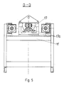
- the support arm set 1e carries burners 15 and 16 for heating the profile edges 17a and the profiles 17 (FIG. 5).
- An additional head 18 sits on the support arm set 1e for dressing the heated profile edges 17a.
- the servo motor 12 serves to feed a movable dressing tool 11a in the pre-dressing head 11.
- a servo motor 19 serves to rotate the pre-dressing head 11 together with its servo motor 12 by an angle of approximately 30 °.
- a correspondingly deformed profile 17 can thus be pre-dressed by the pre-dressing head 11 and its servo motor 12.
- One end of the profile 17 is inserted into the opening of the pre-dressing head 11 by a conveyor (not shown), the opening being created by moving the movable dressing tool 11a upwards with the aid of the servo motor 12.
- the profile 17 is dressed at the end piece mentioned in that the movable dressing tool 11a is pressed in the direction of an associated stationary dressing tool 11b with the aid of the servo motor 11.
- the profile 17 can be pushed further, whereby the dressed profile end piece is displaced into the opening formed by the movable dressing tool 7a, which sits on the holder 7 fastened to the slide 4. Thereafter, with the help of the servo motor 8 and via the movable dressing tool 7a, pressure is exerted on the end piece of the profile 17, the required clear width being set between the dressing tools 11a and 11b of the pre-dressing head 11. Furthermore, the hydraulic servo motors 5 and 6 Movement of the carriage 4 with its seated holders 7 and 9 actuated. The holder 9 is not yet effective in this dressing phase.
- the following section is then dressed like the previous one, the profile 17 being inserted into the roller head 13 in the second cycle and being pressed through it to the additional head 18.
- the profile 17 is fixed on the holder 9.
- the additional head 18 is provided for profiles 17 with profile edges 18a, which have been heated by means of the burners 15 and 16 arranged on the support arm set 1e.
- the roller head 13, which can be moved up and down in the support arm set 1d by the servo motor 14, provides for the final profile formation of the three main surfaces of the profile 17, the deformed profile edges 17a being bent into the correct position and arch or bending deformations of the dressing Profile 17 are eliminated.
- the dressing of these arc or bending deformations is carried out with the hydraulic servomotors 5 and 6 at a standstill by the vertical displacement of the roller head 13 up and down with the aid of the servo motor 14, thereby realizing a deformation value read from a scale that results from the free adjustment of the roller head 13 after the hydraulic servo motor 14 is released.
- torsional deformations of the profiles 17 are eliminated, the respective profile 17 being inserted into the device when the servomotors 5 and 6 are switched off, fixed in the holder 7 or in the holders 7 and 9 with the servo motor 19 being released, and the pre-dressing head 11 being deflected accordingly becomes.
- the pre-dressing head 11 is deflected by an angle corresponding to the torsional deformation of the profile 17 with respect to the axis of the device. By returning the pre-dressing head 11 in the opposite direction by the identical value of the angle of rotation using the hydraulic servo motor 19, the torsional deformation of the profile 17 is eliminated. When the dressing of the profile 17 is finished, it is transported to the storage location in the aligned state.
Landscapes
- Engineering & Computer Science (AREA)
- Mechanical Engineering (AREA)
- Heat Treatment Of Articles (AREA)
- Straightening Metal Sheet-Like Bodies (AREA)
- Devices For Post-Treatments, Processing, Supply, Discharge, And Other Processes (AREA)
- Machines For Laying And Maintaining Railways (AREA)
- Bulkheads Adapted To Foundation Construction (AREA)
Applications Claiming Priority (2)
| Application Number | Priority Date | Filing Date | Title |
|---|---|---|---|
| PL26218286A PL153047B1 (en) | 1986-10-31 | 1986-10-31 | Device for regenerating open-box shapes,especially of water-tight piles and sheet-piles |
| PL262182 | 1986-10-31 |
Publications (3)
| Publication Number | Publication Date |
|---|---|
| EP0265801A2 EP0265801A2 (de) | 1988-05-04 |
| EP0265801A3 EP0265801A3 (en) | 1988-08-10 |
| EP0265801B1 true EP0265801B1 (de) | 1991-07-10 |
Family
ID=20033327
Family Applications (1)
| Application Number | Title | Priority Date | Filing Date |
|---|---|---|---|
| EP19870115193 Expired - Lifetime EP0265801B1 (de) | 1986-10-31 | 1987-10-16 | Vorrichtung zum Abrichten offener Profile |
Country Status (7)
| Country | Link |
|---|---|
| EP (1) | EP0265801B1 (cs) |
| JP (1) | JPS63115620A (cs) |
| CS (1) | CS771487A2 (cs) |
| DD (1) | DD267441A5 (cs) |
| DE (1) | DE3771299D1 (cs) |
| HU (1) | HU200566B (cs) |
| PL (1) | PL153047B1 (cs) |
Families Citing this family (1)
| Publication number | Priority date | Publication date | Assignee | Title |
|---|---|---|---|---|
| CN103230959B (zh) * | 2013-04-07 | 2015-07-01 | 江阴江顺铝型材成套设备制造有限公司 | 导轨与移动端钳口支架配合结构 |
Family Cites Families (5)
| Publication number | Priority date | Publication date | Assignee | Title |
|---|---|---|---|---|
| DE1253999B (de) * | 1964-12-10 | 1967-11-09 | Rmi Gmbh & Co Kg | Hydraulische Richtpresse |
| US3257832A (en) * | 1965-03-01 | 1966-06-28 | Harvey Aluminum Inc | Method and apparatus for finishing extrusions |
| DE2057302C3 (de) * | 1970-11-21 | 1979-02-01 | Wilhelm 2831 Wesenstedt Sudmann | Vorrichtung zum Richten von Spundbohlen oder ähnlichen Werkstücken |
| PL129119B1 (en) * | 1980-03-25 | 1984-03-31 | Przedsieb Budownictwa Inzynier | Method of and apparatus for regenerating shapes of open cross-section in particular sheet piles and water-tight piles |
| DE3309572A1 (de) * | 1983-03-17 | 1984-09-20 | Maschinenfabrik Christian Häusler AG, Duggingen | Richt- und kalibriermaschine |
-
1986
- 1986-10-31 PL PL26218286A patent/PL153047B1/pl unknown
-
1987
- 1987-10-16 DE DE8787115193T patent/DE3771299D1/de not_active Expired - Fee Related
- 1987-10-16 EP EP19870115193 patent/EP0265801B1/de not_active Expired - Lifetime
- 1987-10-26 HU HU476387A patent/HU200566B/hu not_active IP Right Cessation
- 1987-10-28 CS CS877714A patent/CS771487A2/cs unknown
- 1987-10-29 DD DD30842187A patent/DD267441A5/de not_active IP Right Cessation
- 1987-10-31 JP JP27724187A patent/JPS63115620A/ja active Pending
Also Published As
| Publication number | Publication date |
|---|---|
| JPS63115620A (ja) | 1988-05-20 |
| HUT45416A (en) | 1988-07-28 |
| HU200566B (en) | 1990-07-28 |
| PL262182A1 (en) | 1988-06-23 |
| PL153047B1 (en) | 1991-02-28 |
| DE3771299D1 (de) | 1991-08-14 |
| EP0265801A2 (de) | 1988-05-04 |
| CS771487A2 (en) | 1990-05-14 |
| EP0265801A3 (en) | 1988-08-10 |
| DD267441A5 (de) | 1989-05-03 |
Similar Documents
| Publication | Publication Date | Title |
|---|---|---|
| DE2839978C2 (cs) | ||
| DE3346523C2 (de) | Vorrichtung zum Zusammenbau eines Kraftfahrzeug-Körpers | |
| DE2627972C2 (de) | Schwenkbiegemaschine | |
| DE3311766C2 (cs) | ||
| DE2723846A1 (de) | Biegemaschine fuer draht | |
| DE4022951C2 (de) | Biegerichtmaschine für Profilabschnitte | |
| DE2128717C3 (de) | Verfahren zum Aufbringen eines metallischen Abstandhalters auf die Scheibenränder einer der rechteckigen Glasplatten einer Isolierverglasung und Vorrichtung zur Durchführung des Verfahrens | |
| EP2077166B1 (de) | Längsrandbearbeitungsvorrichtung für Bleche | |
| DE1237409B (de) | Vorrichtung zum Schweissen, insbesondere Lichtbogenschweissen, von Traegern aus Blechen | |
| DE2943960A1 (de) | Verfahren zur ausbildung von rohrbogen und einrichtung zur durchfuehrung des verfahrens | |
| AT389657B (de) | Verfahren zum biegen von profil- oder wellblechen und vorrichtung zur durchfuehrung des verfahrens | |
| DE3411023C2 (de) | Vorrichtung zum Herstellen und/oder Bearbeiten von kaschierten Werkstücken | |
| DE2002015A1 (de) | Vorrichtung zum Laengsschweissen von rohrfoermigen Werkstuecken | |
| DE69008120T2 (de) | Vorrichtung zur stufenweisen Positionierung, Bearbeitung und Nachbehandlung von Ecken von aus Kunststoff hergestellten Fenster- oder Türrahmen in einer seitlich angeordneten Arbeitsstelle. | |
| EP0265801B1 (de) | Vorrichtung zum Abrichten offener Profile | |
| DE2621902B2 (de) | Verfahren und Vorrichtung zum Biegen erwärmter Glasscheiben | |
| EP4497515A1 (de) | Biegemaschine zum biegen von flachmaterial und verfahren zum zubiegen eines stehfalzes an einem flachtmaterial unter verwendung der biegemaschine | |
| EP0125540B1 (de) | Vorrichtung zum Herstellen von in der Mantelfläche gelochten Rohren | |
| DE60114045T2 (de) | Vorrichtung zur vervollständigung von verstärkungskäfigen und entsprechendes verfahren | |
| EP0564446A1 (de) | Verfahren und Vorrichtung zum Ausrichten von geraden Stäben | |
| WO1991010519A1 (de) | Biegemaschine zum biegen von stabförmigem material | |
| DE2201791C3 (de) | Einspann- und Richtvorrichtung für aus Blechen gepreßte, vorzugsweise konische, schlitzrohrartige Masten o.dgl. bei einer Rohrschweißvorrichtung | |
| DE4034248A1 (de) | Vorrichtung zum biegen von blech | |
| DE2248679C3 (de) | Schwenkbiegemaschine | |
| DE2900672A1 (de) | Biegevorrichtung und verfahren zum biegen eines langgestreckten materialstranges |
Legal Events
| Date | Code | Title | Description |
|---|---|---|---|
| PUAI | Public reference made under article 153(3) epc to a published international application that has entered the european phase |
Free format text: ORIGINAL CODE: 0009012 |
|
| AK | Designated contracting states |
Kind code of ref document: A2 Designated state(s): BE DE FR GB IT NL SE |
|
| PUAL | Search report despatched |
Free format text: ORIGINAL CODE: 0009013 |
|
| AK | Designated contracting states |
Kind code of ref document: A3 Designated state(s): BE DE FR GB IT NL SE |
|
| 17P | Request for examination filed |
Effective date: 19881031 |
|
| 17Q | First examination report despatched |
Effective date: 19890519 |
|
| DIN1 | Information on inventor provided before grant (deleted) | ||
| RAP1 | Party data changed (applicant data changed or rights of an application transferred) |
Owner name: KRUPOWICZ, JERZY |
|
| GRAA | (expected) grant |
Free format text: ORIGINAL CODE: 0009210 |
|
| AK | Designated contracting states |
Kind code of ref document: B1 Designated state(s): DE |
|
| REF | Corresponds to: |
Ref document number: 3771299 Country of ref document: DE Date of ref document: 19910814 |
|
| EN | Fr: translation not filed | ||
| PLBE | No opposition filed within time limit |
Free format text: ORIGINAL CODE: 0009261 |
|
| STAA | Information on the status of an ep patent application or granted ep patent |
Free format text: STATUS: NO OPPOSITION FILED WITHIN TIME LIMIT |
|
| 26N | No opposition filed | ||
| PGFP | Annual fee paid to national office [announced via postgrant information from national office to epo] |
Ref country code: DE Payment date: 20001228 Year of fee payment: 14 |
|
| PG25 | Lapsed in a contracting state [announced via postgrant information from national office to epo] |
Ref country code: DE Free format text: LAPSE BECAUSE OF NON-PAYMENT OF DUE FEES Effective date: 20020702 |