EP0265894A2 - Terminal pour la gestion de marchandises utilisant une carte munie d'une mémoire à accès aléatoire - Google Patents
Terminal pour la gestion de marchandises utilisant une carte munie d'une mémoire à accès aléatoire Download PDFInfo
- Publication number
- EP0265894A2 EP0265894A2 EP87115703A EP87115703A EP0265894A2 EP 0265894 A2 EP0265894 A2 EP 0265894A2 EP 87115703 A EP87115703 A EP 87115703A EP 87115703 A EP87115703 A EP 87115703A EP 0265894 A2 EP0265894 A2 EP 0265894A2
- Authority
- EP
- European Patent Office
- Prior art keywords
- ram card
- ram
- card
- commodity
- cpu
- Prior art date
- Legal status (The legal status is an assumption and is not a legal conclusion. Google has not performed a legal analysis and makes no representation as to the accuracy of the status listed.)
- Withdrawn
Links
Images







Classifications
-
- G—PHYSICS
- G06—COMPUTING OR CALCULATING; COUNTING
- G06F—ELECTRIC DIGITAL DATA PROCESSING
- G06F17/00—Digital computing or data processing equipment or methods, specially adapted for specific functions
-
- G—PHYSICS
- G07—CHECKING-DEVICES
- G07G—REGISTERING THE RECEIPT OF CASH, VALUABLES, OR TOKENS
- G07G1/00—Cash registers
- G07G1/12—Cash registers electronically operated
Definitions
- the present invention relates to a commodity information terminal such as a POS terminal which is used for the inventory control in a retainer's shop or storehouse.
- FIG. 1 is a configuration diagram of a POS terminal, wherein numeral 10 designates a keyboard which inputs the information about commodities, numeral 20 designates a display unit which displays the information about commodities inputted by the keyboard, numeral 30 designates a printer which prints out the information about commodities, numeral 40 designates a CPU which controls the above-mentioned three kinds of devices, and numeral 50 designates a ROM in which the transfer program is recorded and which transfers the programs recorded in a FDD sheet 102 onto a RAM 80 through a FDD control unit 90.
- numeral 10 designates a keyboard which inputs the information about commodities
- numeral 20 designates a display unit which displays the information about commodities inputted by the keyboard
- numeral 30 designates a printer which prints out the information about commodities
- numeral 40 designates a CPU which controls the above-mentioned three kinds of devices
- numeral 50 designates a ROM in which the transfer program is recorded and which transfers the programs recorded in a FDD sheet 102 onto a RAM 80 through
- the operation of the terminal will now be explained.
- the POS terminal is set in a store for the first time, since a POS terminal has no commodity registering programs recorded in a RAM 80, the resident program in the ROM 50 is to be executed.
- the FDD control unit 90 By using the FDD control unit 90, the commodity registering programs recorded within a FDD sheet 102 are read out in sequence and transferred onto the RAM 80.
- the commodity registering programs transferred in the RAM 80 are in no time started so as to operate the keyboard 10, the display unit 20 and the printer 30, that is, the POS terminal begins to operate as a whole.
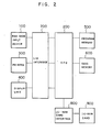
- numeral 100 designates a bar code input device for commodity registering
- numeral 200 designates a CPU
- numeral 300 designates a printer
- numeral 400 designates a display unit
- numeral 500 designates a program memory
- numeral 600 designates a data memory
- numeral 700 designates an I/O interface
- numeral 800 designates an IC RAM card interface
- numeral 900 designates an IC RAM card.
- the results of the calculation are printed out through the I/O interface 700 by the printer 300 or indicated on the display 400 and at the same time the various kinds of accumulators inside the data memory are updated.
- the IC-RAM card 900 can be arbitrarily exchanged by making use of the characteristics of the IC-RAM card.
- a POS terminal with an IC-RAM card incorporated makes a cashier enable to exchange the IC-RAM card arbitrarily.
- the terminal will read and write the information in the IC-RAM card wrongly, which is the new problem occurred in the system.
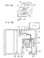
- FIGS. 3A, 3B are views which show safety systems aiming at the protection of data in the conventional cash register, therein numeral 31 designates a keyboard which inputs the information about commodity trading, numeral 32 designates a display unit which indicates the information about commodity trading inputted by the keyboard 21, numeral 33 designates a printer which prints out the information about commodity trading inputted by the keyboard 21, numeral 34 designates such a data write/read unit as FDD device which records the information about commodity trading, numeral 35 designates such a recording medium as FDD sheet which is able to be put into and out of the data write/read unit 34, numeral 36 designates a data write/read controlling circuit which controls the data write/read unit 34, and numeral 37 designates a CPU.
- numeral 31 designates a keyboard which inputs the information about commodity trading
- numeral 32 designates a display unit which indicates the information about commodity trading inputted by the keyboard 21
- numeral 33 designates a printer which prints out the information about commodity trading inputted by the keyboard 21
- numeral 34 designates
- Numeral 38 designates an assembly which is mounted on the data write/read unit 34 by means of springs
- numeral 39 designates lock bellows which is set so as to be fitted in the assembly 38
- numeral 40 designates a lock which is so composed as to slide on the assembly 38
- numeral 41 designates a solenoid which is fixed to the assembly 38 and attached on the lock bellows 39 by means of springs
- numeral 42 designates a front panel which is mounted on the data write/read unit 34 by means of springs so as to be fitted in the lock 40
- numeral 43 designates a push button that is set on the assembly 38.
- the CPU 37 analyzes and processes the information and indicates the results on the display 32 and prints them on the recording sheet of the printer, and at the same time records the information about commodity trading on the recording medium 35 in the data write/read unit 34 through the data write/read circuit 36.
- the conventional data protection safety system for the recording medium is composed of both mechanical parts and electric circuits, so, as its result, the system composition necessarily becomes complicated and it is inevitable to continue to supply power while the data protection and safety system is operated, and still during the operation of the data protection and safety system an operator is unable to exchange the recording medium, which causes such problems as the worsing of operability.
- An object of the present invention is to dissolve the above-mentioned problems, more particularly, to provide a small and cheap register which can execute programs without using I/O devices such as floppy disks and so forth as well as to reduce the register rise time.
- Another object of the invention is to provide a POS terminal with RAM card incorporated which can detect automatically whether an IC RAM card is inserted or not so as to prevent the use of the bad card in advance by diagnosis of the RAM card and also find easily the wrong setting of the RAM card.
- a further object of the invention is to make the data write/read unit smaller and to build the write/read safety system to the recording medium without supplying power and to make smaller the commodity information register including cash register and also to improve the operability so that an operator is able to exchange the RAM card without considering the recording state of the recording medium.
- Yet another object of the invention is to cut off the power supply to the RAM card and make the interface circuit high impedance at least a part between the CPU and the RAM card so as to make the RAM card insensitive before it is to be pulled out, namely, insensitive to the transient bad conditions which happen when the RAM card is to be pulled out.
- a still further object of the invention is to make the CPU able to read and write the RAM card after the protecting cover comes back to the mounting position which is set in advance so as to make the situation in which the RAM card can be used after going through the transient state, that is, making the situation where the data already stored in the RAM card cannot be destroyed regardless of how the RAM card is inserted or operated.
- An additional object of the invention is to have the function of neglecting the data input from the input means while the protection cover of the invention is left open so as to protect from deletion of the information about commodities and commodity trading, inputted by the input means when the RAM card is removed.
- the POS terminal according to the invention is one that executes the program previously recorded in the RAM card by connecting the card to the commodity information register so as to do the commodity registering job as a commodity information register.
- the POS terminal according to the invention is the RAM-card-acceptable commodity information terminal which has a sensor detecting whether the cover of the RAM card is correctly closed or not so as to detect the inserting timing of the RAM card and which makes use of the RAM card as data file or program file and automatically diagnoses whether the RAM card is correctly inserted or not, by detecting automatically the inserted time of the RAM card.
- the data write/read safety system is one which uses as recording medium the compact card type medium made of a memory chip and which has the protecting cover to protect and store the data recording medium incorporated so as to protect the data in the RAM card as the recording medium by detecting the change of the setting state of the protection cover.
- FIG. 4 shows a constitution of a POS terminal, wherein numeral 10 designates a keyboard which inputs the commodity information, numeral 20 designates a display unit which indicates the commodity information inputted by the keyboard 10, numeral 30 designates a printer which prints out the commodity information, numeral 40 designates a CPU which controls the above-mentioned three devices, and numeral 60 designates an IC-RAM card control unit which assembles and controls an IC-RAM card and to which an IC-RAM card 70 recording programs is connected. Numeral 50 designates a ROM on which is recorded the program to start that within the IC-RAM card.
- FIG. 10 designates a keyboard which inputs the commodity information
- numeral 20 designates a display unit which indicates the commodity information inputted by the keyboard 10
- numeral 30 designates a printer which prints out the commodity information
- numeral 40 designates a CPU which controls the above-mentioned three devices
- numeral 60 designates an IC-RAM card control unit which assembles and controls an
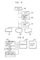
- FIG. 5 is a configuration diagram of an IC-RAM card control unit, wherein numeral 70 designates an IC-RAM card which is connected to a connector 120. Numeral 101 designates an IC-RAM card detecting circuit which discriminates whether the IC-RAM card is connected or not, numeral 110 designates an IC-RAM card power source control circuit which controls the power supply to the IC-RAM card, and the IC-RAM card 70 is connected to a CPU bus 130.
- FIG. 6 is a flow chart which shows the procedure of processing the program recorded in the ROM 50.
- the program recorded in the ROM is started.
- the procedure of processing the program in the ROM will be explained referring to the flow chart in FIG. 6.
- the program is started interruption from the printer and so forth is all forbidden (step 21)
- the information about the loading of the IC-RAM card 70 is read from the IC-RAM card loading detecting circuit 101 (step 22). If the IC-RAM card 70 is not inserted, the information about the loading of the IC-RAM card is read again and the processing is continued until the IC-RAM card 70 is inserted.
- the power input command is issued to the IC-RAM card power control circuit 110 (step 24) so that the IC-RAM card is at the usable state.
- step 25 After the power for the IC-RAM card is on and a given period of waiting time passes (step 25), if the memory of the IC-RAM card 70 becomes accessible normally, the program jumps to the program execution starting address in the IC-RAM card 70 (step 26) and the program in the IC-RAM card is started. And then the programs in the IC-RAM card 70 enable the POS terminal to execute the sale register job by means of the display 20, the keyboard 10, the printer 30 and so forth.
- FIG. 7 is an appearance view of a POS terminal, wherein numeral 20 designates a display which indicates the results of, for example, commodity prices inputted or messages to an operator when the operator operates the keys (hereinafter described), and which has a display part 1A and a display cover 1B covering around the display part 1A.
- numeral 10 designates a keyboard which inputs the sale data and customer's inquiry data in the commodity sale register job, and which has keys 2A used for the input and a keyboard cover 2B covering around the keys 2A.
- Numeral 30 designates a printer which prints and outputs the results of processing of a program storing ROM 2C and a CPU 40 installed inside the keyboard cover 2B onto a sheet and a journal (not shown), and which has a main frame 3A and a printer cover 3B covering the main frame 3A.
- Numeral 4 designates a drawer which stores cash and is opened or closed by the operation of the ROM 50 and the CPU 40 operated by the keys 2A of the keyboard 10. The drawer 4 is inserted removably in a box-shaped base on which the covers 1B, 2B, 3B are mounted.
- Numeral 5 depicts a base of the register.
- Numeral 70 designates an IC-RAM card which is as small as a credit card in size and has the memory capacity of 128 K bytes or 512 K bytes and whose memory is stored by a battery, and which has a connector 6A at the top end.
- Numeral 7 designates a card inserting member which has a card inserting slit 7A for inserting the IC-RAM card 70 and which is set at the place surrounded by the keyboard cover 2B and the printer cover 3B.
- the card inserting slit 7A and is opened at the front side (front side of the terminal) of the card inserting member 7 and inclined slightly downward towards the rear side of the inserting member 7 and is opened also at the rear side of the inserting member 7.
- Numeral 8 designates an IC-RAM card control substrate which serves as I/O interface of the IC-RAM card 70 and which is attached on the base 5 as extending upward and downward a little slantly and is connected to the CPU 2D.
- Numeral 8A designates a connector of the IC-RAM card control substrate 8, and when the IC-RAM card 70 is inserted in the card inserting slit 7A the connector 8A is connected to the connector 6A of the IC-RAM card 70 and relays the information from and to the IC-RAM card 70.
- any kind of card will be allowed to be in place of the card 70; such card which is writable as a photo card, a magnetic card and so on will do.
- the connecting way of the connectors 6A, 8A is not limited to only mechanical contact but optical or magnetical contact or some others may be applied; the types of connecting way matters little if only it will be able to send or receive the information signals.
- Numeral 9 designates a card cover which is attached on the base 5 removably as locating in the space above the base 5 surrounded by the keyboard cover 2B and the printer cover 3B. The card cover 9 covers the card inserting member 7 and the IC-RAM card control substrate 8 so that the IC-RAM card 70 inserted in the card inserting slit 7A cannot be pulled off from outside under such covering condition by the cover 9.
- the card cover 9 is shaped as shown in the drawing, and each surface is of such shape and size to be flush with each of respective surfaces of the keyboard cover 2B, the printer cover 3B and the box-shaped base 5 in the vicinity.
- Numeral 11 designates a lock key which controls the closing and opening of the printer cover 3B and the card cover 9 and is operated at two stages by different keys (not shown). That is, as shown in FIG. 5, one key can operate at the range A ⁇ B (90°), and the other at the range A ⁇ B (180°). If the lock key 11 is turned counterclockwise to B ⁇ A through 90 degrees, only the printer cover 3B is removed from upper side of the box-shaped base 5.
- the card cover 9 is removed from upper side of the box-shaped base 5 and the printer cover 3B is removed from the box-shaped base 5.
- various kinds of detection methods generally known may be used; that is, optical, mechanical or magnetical sensor may be used at the card inserting member 7, and further there is a way to check the I/O bus signals of the IC-RAM card 70 on the program.
- the control can be all executed by hardware and the program in the ROM becomes unnecessary in this case.
- the POS terminal can be used not only for the commodity dealing but also for the inventory control in the warehouse.
- FIG. 9 is a block configuration diagram of a POS terminal in another embodiment
- FIG. 10 is a processing flow chart of the program.
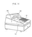
- FIG. 11 is an appearance view of a POS terminal
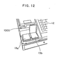
- FIG. 12 is a view illustrating the state that the IC-RAM card cover is opened.
- numeral 100 designates a bar code input unit which registers commodities
- numeral 200 designates a CPU
- numeral 300 designates a printer
- numeral 400 designates a display
- numeral 500 designates a program memory
- numeral 600 designates a data memory
- numeral 700 designates an I/O interface
- numeral 800 designates an IC-RAM card interface
- numeral 900 designates an IC-RAM card
- numeral 1000 designates a sensor which detects whether the cover of the IC-RAM card is closed or not.
- numeral 20 designates a display
- numeral 30 designates a printer
- numeral 111 designates an IC-RAM card cover
- numeral 10 designates a keyboard.
- numeral 1000 designates a cover opening sensor
- numerals 13a, 13b designate two card inserting members into which IC-RAM cards 900 are inserted and for which two cards are available at one time (e.g., one of the two cards stores programs and the other stores the commodity information command).
- the opening or closing of the IC-RAM card is detected optically in the above embodiment, another may be applied if the loading of the IC-RAM card can be detected (e.g., electrostatic capacity method and so on), and besides IC, different kinds of means which apply other principles such as light, magnetism and the like may be used with similar effects to the above.
- FIGS. 13A, 13B the commodity sale information about price, commodity code, for example, inputted by a keyboard 51 is calculated and sorted in a CPU 57, and its results are indicated on an operator's display 52 and a customer's display 71 and printed out by a printer 53.
- the statistical data of the trading time, the sold commodity code, sold amount and a dealer's name are accumulated in an accumulator in the RAM 72.
- the calculation and sorting are executed in the CPU 57 which reads the program written in the ROM 70.
- a drawer 73 is opened in accordance with the control of the CPU 57.
- a second drawer 74 is connected so as to manage sales cash by each operator.
- a timer 75 the time information, for example, year, month, day, hour, minute and the like, to the CPU 57.
- the commodity codes some of them are symbolized into bar codes, so in this case the commodity codes are not read by manual input from the keyboard but automatically read and inputted by a commodity code reader 76.
- the CPU 57 executes it by way of a communication control unit 77. For example, when the statistical information of the accumulator in the commodity information register is sent to the host computer, the CPU 57 reads the content of the accumulator and gives the transmission data to the communication control unit 77.
- the communication control unit 77 sends the data to the host computer, and informs the CPU 57 of the result regarding whether it is finished or not.
- a second communication control unit 78 executes the communication between other communication instruments.
- the two communication control units 77, 78 enables the communication between the plural number of other information devices simultaneously.
- IC-RAM cards 79, 80 (FIG. 13B) are readable memory cards which have the connector removably inserted into an IC-RAM card control unit 81.
- the commodity information inputted from the keyboard 51 and from the commodity code reader 76 of the commodity trading information inputted or outputted from the communication control units 77, 78 is read to the IC-RAM cards 79, 80 through the IC-RAM card control unit 81.
- the IC-RAM cards 79, 80 which are pulled off from the IC-RAM card control unit 81 and connected to the IC-RAM card controller of the host computer and other information devices, can send the commodity information in the IC-RAM card without using information instruments that need some cables for the transmission of the data.
- the protection cover covering the IC-RAM cards 79, 80 is removed.
- the removal of the cover is detected by a protection cover sensor 82 and informed to the CPU 57.
- Some kinds of commodities require the terminal to be connected to a balance to weigh so as to input the weight information, or to a magnetic card reader that can read a credit card and so on, and these instruments perform the information input by way of I/O control units 83, 84.
- Such instruments as the commodity code reader 76, the communication control units 77, 78, the customer's display 71, the IC-RAM card control unit 81, and the I/O control units 83, 84 are optional. Namely, these are constituted in units so as to be fitting with the main commodity information terminal, and each of units is removably connected to the option unit connecting substrate 35 by way of connector.
- the IC-RAM card control unit 81 can load the plural number of IC-RAM cards 79, 80 at one time, and the these plural IC-RAM cards can be applied to other purposes.
- the IC-RAM card 79 may record the statistical information about the commodity trading
- the IC-RAM card 80 may store the information about commodities such as unit price and name.
- numeral 57 designates a CPU
- numeral 86 designates a protection cover
- numeral 82 designates a sensor (photo, ultrasonic, piezo-electric element may be utilized)
- numerals 79, 80 designate IC-RAM cards
- numeral 81 designates an IC-RAM control substrate which has a connector that can removably load the IC-RAM card, and which has interface function of the CPU and the IC-RAM card.
- the light reception and emission element may be used as a sensor.
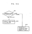
- a protection cover sensor 82 comprises a light emission portion and a light reception portion, and the protection cover 86 intercepts the light path lying between the light emission portion and the light reception portion when the protection cover 86 is installed at a predetermined position (hereinafter referred to as "normal position").
- the CPU 57 regards the protection cover 86 as being at the normal position, with the result that the power source is supplied to the IC-RAM card control substrate 81 and the IC-RAM cards 79, 80, and the CPU 57 reads or writes the information about commodity trading from or to the IC-RAM cards 79, 80 by means of the IC-RAM card control substrate 81. As shown in FIG.
- the CPU 57 detects that the IC-RAM cards 79, 80 are in the removable state. With the time information (about tens m/sec) that comes from the timer 75 at regular interval, the CPU 57 is detecting at the constant interval whether the protection cover 86 is at the normal position or not. This detection is continued even while the IC-RAM card control unit 81 executes writing of the data to the IC-RAM cards 79, 80.
- the CPU 57 detects the deviation of the protection cover 86 from normal position, the power supply line to the IC/RAM cards 79, 80 is interrupted in the IC-RAM card control unit 81 thereby the power supply to the IC-RAM cards 79, 80 is stopped.
- the flow chart of the above operation is shown in FIG. 14C.
- the data is written to the IC-RAM card, the data is divided into several blocks so as to write by the unit, and while the data is written to the IC-RAM cards 79, 80, if the change of the position of the protection cover 86 is detected, the process of writing the unit block is finished and then the power supply to the IC-RAM cards 79, 80 is immediately stopped.
- the above-mentioned timing is shown in FIG. 15.
- the period from detecting the change of the position of the protection cover 86 until stopping the power supply to the IC-RAM cards 79, 80 is much shorter than the period of time for pulling out the IC-RAM cards 79, 80 after opening the protection cover 86, so whenever the protection cover 86 is removed, the power supply to the IC-RAM cards 79, 80 is stopped by the time when the IC-RAM cards 79, 80 are pulled out, and since the electric transient state never occurs between the IC-RAM cards 79, 80 and the IC-RAM card control substrate 81, in whatever state and procedure the IC-RAM cards 79, 80 may be pulled out, the data in the IC-RAM cards 79, 80 can never be destroyed.
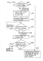
- embodiment 1 Only differences from embodiment 1 will be described. Being continued from the state of embodiment 1, when the protection cover is installed at the normal position where the protection cover is extended over the IC-RAM cards, the information that the protection cover is set in the normal position is sent through the protection cover sensor to the CPU, which supplies the power to the IC-RAM cards through the IC-RAM card control substrate and at the same time makes it possible that the IC-RAM cards read and write the data.
- the operation flow chart is shown in FIG. 14D. Other conditions are the same as embodiment 1.
- the CPU When the CPU detects the protection cover attached at the normal position, the CPU supplies the power to the IC-RAM cards through the IC-RAM card control substrate so as to confirm the discrimination marks previously written in the IC-RAM cards. After the discrimination marks confirm that the corresponding IC-RAM cards are suitable for the processing of the information about commodities and commodity trading, the CPU processes the information about commodities and commodity trading inputted from the keyboard or the input means.
- the operation flow chart is shown in FIG. 14E. Other conditions are the same as embodiment 2.
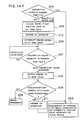
- the CPU When the CPU detects the protection cover attached at the normal position, the CPU supplies the power to the IC-RAM cards through the IC-RAM card control substrate so as to confirm the discrimination marks previously written in the IC-RAM cards. After the discrimination marks confirm that the corresponding IC-RAM cards are suitable for the processing of the information about commodities and commodity trading, the CPU informs an operator of that the information about commodities and commodity trading is able to be processed by the input means through such means as the indicated messages on a display, the printed messages or the sound messages from a speaker.
- the CPU processes the information about commodities and commodity trading from the keyboard or the input means after it executes the notification to the operator.
- the operation flow chart is shown in FIG. 14F. Other conditions are the same as embodiment 2.
- the RAM card which is removable is used as the main memory of the CPU, thereby the program of the commodity information terminal to execute the commodity register job is previously recorded in the RAM card, and the program is started and the commodity register job can be carried out only by connecting the RAM card to the commodity information terminal. Consequently, the program can be executed without using the I/O devices such as the floppy disk, and the small and cheap commodity information register is provided, and further the rise time of the register can be reduced.
- the system since the loading timing of the IC-RAM card is automatically detected and the diagnosis of the IC-RAM card can be executed automatically, the system is prevented from the trouble caused by the wrong loading of the IC-RAM card.
- the data protecting system is so composed as to use the IC-RAM card as a recording medium and as to detect the approaching to the IC-RAM card electrically and as to interrupt the power supply to the IC-RAM card before the IC-RAM card is pulled off, an operator of the register is able to operate freely at any time without being conscious of the operating state of the IC-RAM card, thereby the operability is improved and the instrument is small-sized.
Landscapes
- Physics & Mathematics (AREA)
- Engineering & Computer Science (AREA)
- General Physics & Mathematics (AREA)
- Theoretical Computer Science (AREA)
- Data Mining & Analysis (AREA)
- Databases & Information Systems (AREA)
- Mathematical Physics (AREA)
- Software Systems (AREA)
- General Engineering & Computer Science (AREA)
- Cash Registers Or Receiving Machines (AREA)
- Techniques For Improving Reliability Of Storages (AREA)
- Management, Administration, Business Operations System, And Electronic Commerce (AREA)
Applications Claiming Priority (6)
| Application Number | Priority Date | Filing Date | Title |
|---|---|---|---|
| JP258985/86 | 1986-10-30 | ||
| JP25898586A JPS63113696A (ja) | 1986-10-30 | 1986-10-30 | 商品情報タ−ミナル |
| JP258984/86 | 1986-10-30 | ||
| JP25898686A JPH0661086B2 (ja) | 1986-10-30 | 1986-10-30 | 商品情報レジスタ |
| JP25898486A JPS63113665A (ja) | 1986-10-30 | 1986-10-30 | Ramカ−ド利用商品情報タ−ミナル |
| JP258986/86 | 1986-10-30 |
Publications (2)
| Publication Number | Publication Date |
|---|---|
| EP0265894A2 true EP0265894A2 (fr) | 1988-05-04 |
| EP0265894A3 EP0265894A3 (fr) | 1989-10-25 |
Family
ID=27334775
Family Applications (1)
| Application Number | Title | Priority Date | Filing Date |
|---|---|---|---|
| EP87115703A Withdrawn EP0265894A3 (fr) | 1986-10-30 | 1987-10-27 | Terminal pour la gestion de marchandises utilisant une carte munie d'une mémoire à accès aléatoire |
Country Status (2)
| Country | Link |
|---|---|
| EP (1) | EP0265894A3 (fr) |
| KR (1) | KR910001711B1 (fr) |
Cited By (3)
| Publication number | Priority date | Publication date | Assignee | Title |
|---|---|---|---|---|
| WO1990001199A1 (fr) * | 1988-07-28 | 1990-02-08 | British Airways Plc | Appareil d'enregistrement de transactions |
| WO1996019782A1 (fr) * | 1994-12-22 | 1996-06-27 | Trefon Kommunikationssysteme Gmbh | Caisse enregistreuse pourvue d'une memoire de donnees |
| US6401007B1 (en) | 1999-04-16 | 2002-06-04 | Kalish Canada Inc. | Gage element for performing automatic setting of a machine for manipulating articles, such as a palletization machine |
Family Cites Families (3)
| Publication number | Priority date | Publication date | Assignee | Title |
|---|---|---|---|---|
| JPS533755A (en) * | 1976-06-30 | 1978-01-13 | Tokyo Electric Co Ltd | Goods sales management system |
| DE2840981C2 (de) * | 1977-10-08 | 1984-03-29 | Tokyo Electric Co., Ltd., Tokyo | Speichereinsatz für elektronische Registrierkassen und Datenverarbeitungseinheiten |
| JPH0697472B2 (ja) * | 1985-10-25 | 1994-11-30 | オムロン株式会社 | 電子式キヤツシユレジスタ |
-
1987
- 1987-10-23 KR KR1019870011809A patent/KR910001711B1/ko not_active Expired
- 1987-10-27 EP EP87115703A patent/EP0265894A3/fr not_active Withdrawn
Cited By (3)
| Publication number | Priority date | Publication date | Assignee | Title |
|---|---|---|---|---|
| WO1990001199A1 (fr) * | 1988-07-28 | 1990-02-08 | British Airways Plc | Appareil d'enregistrement de transactions |
| WO1996019782A1 (fr) * | 1994-12-22 | 1996-06-27 | Trefon Kommunikationssysteme Gmbh | Caisse enregistreuse pourvue d'une memoire de donnees |
| US6401007B1 (en) | 1999-04-16 | 2002-06-04 | Kalish Canada Inc. | Gage element for performing automatic setting of a machine for manipulating articles, such as a palletization machine |
Also Published As
| Publication number | Publication date |
|---|---|
| KR880005536A (ko) | 1988-06-29 |
| EP0265894A3 (fr) | 1989-10-25 |
| KR910001711B1 (ko) | 1991-03-19 |
Similar Documents
| Publication | Publication Date | Title |
|---|---|---|
| US4870604A (en) | Portable data processing device | |
| EP0256768B1 (fr) | Dispositif pour le traitement de transactions | |
| CN104346885A (zh) | 商品销售数据处理装置及控制方法 | |
| EP0249852B1 (fr) | Terminal muni d'une imprimante | |
| US6553348B1 (en) | Sales management apparatus | |
| EP0827101A2 (fr) | Lecteur de carte magnétique | |
| KR910001711B1 (ko) | 상품정보 터미널 및 레지스터 | |
| JP3100514B2 (ja) | カード式自動販売機 | |
| EP0345328B1 (fr) | Dispositif electronique a transducteur magnetique et son mode d'entretien | |
| US20170142266A1 (en) | Control Method of a Printer, Printer, and Printer Set | |
| JPH0661086B2 (ja) | 商品情報レジスタ | |
| JP2661559B2 (ja) | 取引処理方法 | |
| JP2788828B2 (ja) | データ処理装置 | |
| JP2583881B2 (ja) | カ−ドによる管理情報処理方法 | |
| JP2549758B2 (ja) | 商品販売データ処理装置 | |
| JPH0758516B2 (ja) | Icカ−ド装置 | |
| JPH02105987A (ja) | 磁気カードの再発行システム | |
| JP2003177918A (ja) | インストール方法および制御機器 | |
| JPH08161603A (ja) | カード式自動販売機 | |
| JPH1091852A (ja) | 情報記録媒体処理装置及び情報記録媒体処理システム | |
| JPS62169265A (ja) | 現金自動取引装置 | |
| JPH0417475B2 (fr) | ||
| JPS62138990A (ja) | 小型電子機器 | |
| JPH0335380A (ja) | プリペイドカードの処理装置 | |
| JPH04367015A (ja) | 周辺機器制御装置 |
Legal Events
| Date | Code | Title | Description |
|---|---|---|---|
| PUAI | Public reference made under article 153(3) epc to a published international application that has entered the european phase |
Free format text: ORIGINAL CODE: 0009012 |
|
| AK | Designated contracting states |
Kind code of ref document: A2 Designated state(s): DE FR GB IT |
|
| PUAL | Search report despatched |
Free format text: ORIGINAL CODE: 0009013 |
|
| AK | Designated contracting states |
Kind code of ref document: A3 Designated state(s): DE FR GB IT |
|
| 17P | Request for examination filed |
Effective date: 19891125 |
|
| 17Q | First examination report despatched |
Effective date: 19910809 |
|
| STAA | Information on the status of an ep patent application or granted ep patent |
Free format text: STATUS: THE APPLICATION HAS BEEN WITHDRAWN |
|
| 18W | Application withdrawn |
Withdrawal date: 19911125 |
|
| RIN1 | Information on inventor provided before grant (corrected) |
Inventor name: TAKENO, KOUHEIC/O MITSUBISHI DENKI K.K. Inventor name: KITAGUCHI, TOMOKIC/O MITSUBISHI DENKI K.K. Inventor name: KUSANO, NORIMASAC/O MITSUBISHI DENKI K.K. |