EP0265908A2 - Appareil pour l'ébullition du moût - Google Patents
Appareil pour l'ébullition du moût Download PDFInfo
- Publication number
- EP0265908A2 EP0265908A2 EP87115771A EP87115771A EP0265908A2 EP 0265908 A2 EP0265908 A2 EP 0265908A2 EP 87115771 A EP87115771 A EP 87115771A EP 87115771 A EP87115771 A EP 87115771A EP 0265908 A2 EP0265908 A2 EP 0265908A2
- Authority
- EP
- European Patent Office
- Prior art keywords
- wort
- live steam
- partition
- openings
- condensate
- Prior art date
- Legal status (The legal status is an assumption and is not a legal conclusion. Google has not performed a legal analysis and makes no representation as to the accuracy of the status listed.)
- Granted
Links
Images


Classifications
-
- C—CHEMISTRY; METALLURGY
- C12—BIOCHEMISTRY; BEER; SPIRITS; WINE; VINEGAR; MICROBIOLOGY; ENZYMOLOGY; MUTATION OR GENETIC ENGINEERING
- C12C—BEER; PREPARATION OF BEER BY FERMENTATION; PREPARATION OF MALT FOR MAKING BEER; PREPARATION OF HOPS FOR MAKING BEER
- C12C7/00—Preparation of wort
- C12C7/20—Boiling the beerwort
- C12C7/205—Boiling with hops
- C12C7/22—Processes or apparatus specially adapted to save or recover energy
-
- C—CHEMISTRY; METALLURGY
- C12—BIOCHEMISTRY; BEER; SPIRITS; WINE; VINEGAR; MICROBIOLOGY; ENZYMOLOGY; MUTATION OR GENETIC ENGINEERING
- C12C—BEER; PREPARATION OF BEER BY FERMENTATION; PREPARATION OF MALT FOR MAKING BEER; PREPARATION OF HOPS FOR MAKING BEER
- C12C13/00—Brewing devices, not covered by a single group of C12C1/00 - C12C12/04
- C12C13/02—Brew kettles
- C12C13/025—Brew kettles heated with steam
-
- F—MECHANICAL ENGINEERING; LIGHTING; HEATING; WEAPONS; BLASTING
- F28—HEAT EXCHANGE IN GENERAL
- F28D—HEAT-EXCHANGE APPARATUS, NOT PROVIDED FOR IN ANOTHER SUBCLASS, IN WHICH THE HEAT-EXCHANGE MEDIA DO NOT COME INTO DIRECT CONTACT
- F28D7/00—Heat-exchange apparatus having stationary tubular conduit assemblies for both heat-exchange media, the media being in contact with different sides of a conduit wall
- F28D7/10—Heat-exchange apparatus having stationary tubular conduit assemblies for both heat-exchange media, the media being in contact with different sides of a conduit wall the conduits being arranged one within the other, e.g. concentrically
- F28D7/12—Heat-exchange apparatus having stationary tubular conduit assemblies for both heat-exchange media, the media being in contact with different sides of a conduit wall the conduits being arranged one within the other, e.g. concentrically the surrounding tube being closed at one end, e.g. return type
Definitions
- the invention relates to a wort boiling device which works with vapor compression, with a wort kettle and with two separate heating circuits located outside the wort kettle and formed by heat exchangers, one heat exchanger (live steam heat exchanger) for heating the wort with live steam and the other heat exchanger (vapors heat exchanger) for subsequent boiling the wort is fed with condensed vapors.
- the primary purpose of working with two separate heating circuits, one for live steam and one for compressed vapors, is that due to the separation of the heating circuits, the condensate of the live steam can be recycled, i.e. contamination of the boiler and condensate system by vapor components is excluded.
- the object of the invention is therefore to propose a wort boiling device of the type mentioned at the outset, which entails a considerably lower material production and operating outlay than the systems known in the prior art.
- the live steam is also targeted and better by the invention can be used, in particular can be continuously cooked with fresh steam and steam in a cooker.
- the nested arrangement of the heat exchangers in the one outer cooker also leads to better efficiency, since radiation losses from the inner cooker are eliminated.
- the outer cooker is designed as an upright, elongated round container, at the lower end of an inlet and at the upper end an outlet for the wort is formed, the wort on the way from the inlet to the outlet with the Heat exchanger surfaces of the two heat exchangers comes into contact.
- the incoming wort flows through the outer boiler from bottom to top and is heated by sweeping past the heat exchanger surfaces, depending on whether you are working with live steam or with compressed vapor or with both.
- the container is provided in its upper region with a first, upper and horizontally extending partition and in its lower region with a first, lower and horizontally extending partition, the partitions delimiting a central space and that a plurality of openings are present in the dividing walls, a wort conduit penetrating the central space leading from one opening in the first upper dividing wall to a corresponding opening in the first lower dividing wall for passage of the wort.
- the subdivision of the tank with partitions creates a concrete possibility of separate heating circuits or the two heat exchangers separately from one another To accommodate the external cooker.
- the vapor vapor flows around the wort lines in this middle space and cannot escape further up through the upper partition and no further down into the container via the lower partition. In this way, a closed vapor steam heat exchanger is realized in the outer cooker.
- the second heat exchanger is produced in that the container is provided above the first upper partition with a second upper partition and below the first lower partition with a second lower partition, both of which are horizontal and that between corresponding openings of the two Second partitions live steam lines run through the middle space in the wort lines with a smaller diameter than these wort lines.
- the upper second partition runs above the mouth of the outlet for the wort and the second lower partition runs below the mouth of the inlet for the wort.
- the second upper partition and the wort inlet are accommodated in a container attachment, so that the partition can be easily installed.
- a further embodiment provides that the container is closed at its lower end by the second lower partition, with a condensate collecting space with a condensate outlet adjoining the partition at the bottom.
- the second lower partition thus forms the container bottom at least over part of the container width, which also leads to an easier installation of this partition.
- the condensate collection space into which the main steam lines open then follows in the manner of an approach.
- the condensate can flow out of the condensate collecting space through a condensate outlet provided for this purpose, so that the live steam does not come into contact with vapor condensate from the point of entry to the point of exit from the container and can therefore be used further.
- a further advantageous embodiment provides that the container has vertically directed guide walls which are arranged in such a way that they pass through the wort as long as possible from the wort inlet opening to the wort outlet opening. This extends the effective heating and cooking distance for the wort.
- the diameter of the two second partitions corresponds to approximately half the diameter of the two first partitions and that the container attachment and the condensate collection space are arranged symmetrically to the longitudinal center axis of the containers.
- the two heat exchangers are arranged rotationally symmetrically with respect to the longitudinal center axis, so that there is a uniform effect on the wort flowing through from both heat exchangers.
- the wort lines and the live steam lines are designed as round tubes and it is further provided that the bottom of the live steam condensate collection space is convex. In this way, dead corners are avoided and it is ensured that the condensate can run out without leaving any substantial residues in the container.
- an extension is formed which projects into the outer cooker with a cylindrical outer surface up to the lower partition, the extension being divided horizontally by an upper intermediate wall and a lower intermediate wall and with a live steam inlet and a live steam condensate drain is provided.
- the advantage is also achieved that the compensator provided there on the upper attachment can be omitted. This is due to the fact that the spatially combined removal of the live steam condensate and the feed Because of the relatively small temperature differences between steam and condensate, live steam does not experience such high temperature differences. Therefore, no compensation is required with this solution.
- the intermediate walls, in particular the upper intermediate wall can also be realized using a relatively thin metal sheet, since there are no noteworthy pressure differences between these partition walls. The arrangement of the approach also facilitates the assembly, inspection and maintenance of the outer cooker.
- a further embodiment of the invention provides that the upper intermediate wall is provided with openings which are concentric with openings of the lower partition and that associated live steam condensate collecting pipes end at the openings and each extend upwards through the line pipes with radial spacing, the tubes end in the area of the upper partition and are closed there.
- the lower intermediate wall is provided with openings which are concentric with the openings of the upper intermediate wall and it is provided that respectively associated live steam line pipes end at the openings and extend upward through the live steam condensate collecting pipes with a radial spacing.
- the live steam line pipes are open at the top and end at a distance from the upper end of the live steam condensate collection pipes.
- Live steam condensate collection pipe surrounds the live steam line pipe and is closed at the top, the live steam is diverted after exiting the live steam line pipe, condensed and runs inside the live steam condensate collection pipe back down into the live steam condensate collection space formed between the two partitions, from where it is then discharged via an opening.
- the wort boiling device is denoted overall by 1 and comprises a wort pan 2 which is connected to an external boiler 4 via various connecting lines.
- the wort is both heated and boiled in the external cooker 4.
- the wort is introduced via line 5 into the external boiler and leaves it at the upper end via line 6.
- a live steam feed line 9 leads to the outer cooker 4, via which live steam can be introduced into the outer cooker 4 for heating the wort.
- the live steam condensate leaves the external boiler via the outlet line 10.
- the live steam flows through the outer cooker 4 in a separate line system in a manner to be explained in more detail.
- the outer cooker 4 is connected to an inlet line 7, via which vapors compressed with the aid of a compressor 3 can be introduced into the outer cooker.
- the vapor condensate leaves the external boiler 4 via the outlet line 8.
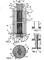
- FIG. 2 shows how the separate heating circuits in the outer cooker 4 and the two heat exchangers are implemented once for live steam and once for compressed vapors in the outer cooker 4.
- the outer cooker 4 is designed as an elongated, upright circular container. Inside, the container is initially provided with a horizontally running partition 13 in the upper area above the inlet opening 18 for the compressed vapors. A corresponding first lower partition 14 is in the lower region of the container 4 below the outlet opening 19 arranged for the vapor condensate. These two first partitions 13 and 14 separate a central space 20 in the container from the spaces adjoining upwards and downwards. There are through openings 15 in the upper partition 13 and corresponding openings 16 in the lower partition 14. The openings 15 and 16 are connected to one another by pipes 17.
- the container 4 also has at its upper end a container attachment 23 on which the wort outlet opening 22 is formed. Above the wort outlet opening 22 there is a second upper partition 25, which in turn is also provided with openings 26.
- the container attachment is provided with a compensator 54 to compensate for different expansions.
- the container bottom 27 is closed at the bottom by a second, lower partition wall 28 over a region symmetrical to the longitudinal central axis A of the outer cooker 4, openings 32 also being present in this second lower partition wall 28. Also run between the openings 26 in the second upper partition 25 and the openings 32 in the second lower partition 28 Pipelines 30, through which live steam, which is introduced via line 9 and live steam inlet 24 at the upper end of the container attachment 23, flow through, condense and collect into the condensate collecting space 29 which adjoins the lower partition 28 downward as live steam condensate. The live steam condensate is then introduced into the condensate line 10 via the outlet 33.
- the wort line pipes 17 running in the inner part of the outer cooker 4 are penetrated by the live steam line pipes 30.
- the diameter of the live steam line pipes 30 is dimensioned such that the wort can also flow through the wort line pipes 17 penetrated by the live steam line pipes 30 without excessive flow resistance.
- the second heat exchanger 12 By separating with the help of the second partitions 25 and 28 and the live steam lines running between these partitions, the second heat exchanger 12 is formed, the heating medium, namely the live steam, without contact with the vapor condensate in a separate heating circuit, namely through the pipes 30 the outer cooker interspersed so that the live steam condensate, which is obtained via line 10, can be used further.
- FIG. 5 it can also be seen that there are also vertically directed guide walls 31 in the outer cooker 4, which guide the wort entering the inlet 21 through the outer cooker 4 as long as possible.
- the guide walls are easy to arrange and manufacture due to the concentrically nested arrangement of the heat exchangers because identical parts can be used.
- the wort boiling device according to the invention can be used as follows.
- the wort is heated by pumping around the wort from the pan 2 with the aid of a pump (not shown in more detail) into the outer cooker 4.
- Fresh steam 9 is introduced into the outer cooker 4 via the line 9 and the inlet 24, which then passes uniformly down the pipes 30 , releases its heat to the wort and condenses in the process.
- the live steam condensate collects in the condensate collection chamber 29 and then leaves the external boiler via the line 10 and can then be used further.
- the heated wort is conveyed back into the pan 7 via the outlet 6 and circulates between the outer cooker 4 and the pan 2 until it has approximately reached boiling temperature. Due to the increasing heating of the wort, 2 vapors are created in the pan.
- the compressor switches on and the vapor flap 2a in pan 2 closes.
- the vapor compressed with the aid of the compressor 3 is then introduced into the external boiler 4 via the line 7 and then takes over the heating of the wort circulating further.
- the compressed vapor condenses when flowing around the wort conduit pipes 7 in the central space 20 of the external boiler 4.
- the vapor condensate can then be removed via the outlet 19 and the conduit 8 and further used, for example, for the preparation of hot water or the like.
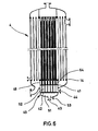
- FIG. 6 shows a further exemplary embodiment of a External cooker 4 shown.
- the live steam supply and the discharge of the live steam condensate take place with the aid of an extension 40 arranged at the lower end of the container.
- This approach projects with a cylindrical outer surface 48 from below through the container bottom to the lower partition 14 and is sealingly attached to this partition 14 all around.
- An upper intermediate wall 41 and a lower intermediate wall 42 are located in the extension. Below the lower intermediate wall 42, the extension 40 is closed and provided with a live steam inlet 43. Openings 45 are formed in the upper intermediate wall 41, which are concentric with the openings 16 of the lower partition 14 (see FIG. 7).
- These condensate collection pipes 46 each extend into the associated line pipes 17 and end approximately in the region of the upper partition 13.
- the live steam condensate collection pipes 46 are closed at the upper end 50.
- Openings are also present in the lower intermediate wall 42 concentrically with the openings 45 and 16 of the upper intermediate wall and the lower dividing wall, in which fresh steam line pipes 47 begin, which extend into the condensate line pipes 46 and end at a distance A from the upper end 50 of the live steam condensate collecting pipes .
- the diameters of the tubes running into one another are selected so that there is a sufficient radial distance R 1 between the conduit pipe 17 and the next internal live steam condensate line tube 46 and also between the live steam line tube 47 and the live steam condensate line tube 46 there is a correspondingly sufficient radial distance R 2, so that a corresponding passage of the wort or . of Live steam condensate is possible.
- This external cooker is operated in analogy to the method of operation described with reference to the first exemplary embodiment, but the live steam is introduced at the bottom via the opening 43.
- the live steam is distributed in the space 51 and enters the live steam line pipes 47 evenly below through the openings 49. There it then rises to the open end of the respective live steam line pipes and is deflected by the closed end 50 of the live steam condensate collection pipe, with the live steam condensate then going down between the outer wall of the live steam line pipes 47 and the inner wall of the live steam condensate collection pipes into the condensate collection space 52, between the upper one Intermediate wall 41 and the lower intermediate wall 42 is running. There is a lateral live steam condensate outlet 44 through which the condensate can then drain.
- Another live steam condensate drain 53 is provided in the live steam distribution chamber 51 in order to be able to discharge the condensed live steam there as well.
- the wort is then heated in analogy to the exemplary embodiment described first in that the wort passes between the line pipes 17 and the live steam condensate line pipes 46 through the external boiler and is heated in the process.
- the wort that collects between the lower partition 14 and the upper intermediate wall 41 emerges laterally through suitable openings 64 from the cylinder jacket of the extension 14 into the radially outer part of the outer boiler.
- the outdoor cookers according to the invention can not only in a standing arrangement, but also be used in a horizontal arrangement.
Landscapes
- Engineering & Computer Science (AREA)
- Chemical & Material Sciences (AREA)
- Organic Chemistry (AREA)
- General Engineering & Computer Science (AREA)
- General Health & Medical Sciences (AREA)
- Wood Science & Technology (AREA)
- Bioinformatics & Cheminformatics (AREA)
- Life Sciences & Earth Sciences (AREA)
- Health & Medical Sciences (AREA)
- Genetics & Genomics (AREA)
- Food Science & Technology (AREA)
- Biochemistry (AREA)
- Zoology (AREA)
- Physics & Mathematics (AREA)
- Thermal Sciences (AREA)
- Mechanical Engineering (AREA)
- Distillation Of Fermentation Liquor, Processing Of Alcohols, Vinegar And Beer (AREA)
- Commercial Cooking Devices (AREA)
Applications Claiming Priority (2)
| Application Number | Priority Date | Filing Date | Title |
|---|---|---|---|
| DE3636491A DE3636491C2 (de) | 1986-10-27 | 1986-10-27 | Würzekochvorrichtung |
| DE3636491 | 1986-10-27 |
Publications (3)
| Publication Number | Publication Date |
|---|---|
| EP0265908A2 true EP0265908A2 (fr) | 1988-05-04 |
| EP0265908A3 EP0265908A3 (en) | 1990-05-16 |
| EP0265908B1 EP0265908B1 (fr) | 1993-05-12 |
Family
ID=6312548
Family Applications (1)
| Application Number | Title | Priority Date | Filing Date |
|---|---|---|---|
| EP87115771A Expired - Lifetime EP0265908B1 (fr) | 1986-10-27 | 1987-10-27 | Appareil pour l'ébullition du moût |
Country Status (4)
| Country | Link |
|---|---|
| US (1) | US4813346A (fr) |
| EP (1) | EP0265908B1 (fr) |
| JP (1) | JPS63177778A (fr) |
| DE (2) | DE3636491C2 (fr) |
Cited By (1)
| Publication number | Priority date | Publication date | Assignee | Title |
|---|---|---|---|---|
| EP0462440A1 (fr) * | 1990-06-19 | 1991-12-27 | ANTON STEINECKER ENTWICKLUNGS GmbH & Co. | Appareil à calandre extérieure pour l'ébullition du moût |
Families Citing this family (10)
| Publication number | Priority date | Publication date | Assignee | Title |
|---|---|---|---|---|
| DE9314102U1 (de) * | 1993-09-17 | 1993-12-23 | Anton Steinecker Entwicklungs Gmbh & Co, 85356 Freising | Sudhausanlage mit mindestens zwei Würzepfannen |
| DE9402547U1 (de) * | 1994-02-16 | 1994-04-14 | Anton Steinecker Entwicklungs Gmbh & Co, 85356 Freising | Würzepfanne zum Kochen von Würze für die Bierherstellung |
| WO2014151340A1 (fr) * | 2013-03-15 | 2014-09-25 | Caloris Acquisition, Llc | Echangeur de chaleur à contre-courant à passe multiple liquide-liquide |
| US11224306B2 (en) | 2016-05-18 | 2022-01-18 | Lg Electronics Inc. | Beverage-making apparatus |
| CN107400585B (zh) * | 2016-05-18 | 2021-07-30 | Lg电子株式会社 | 啤酒酿造装置 |
| CN107400583B (zh) | 2016-05-18 | 2021-07-13 | Lg电子株式会社 | 啤酒酿造包及具有其的啤酒酿造装置 |
| US11208621B2 (en) * | 2016-05-18 | 2021-12-28 | Lg Electronics Inc. | Beverage-making apparatus |
| CN107400586B (zh) | 2016-05-18 | 2021-05-28 | Lg电子株式会社 | 啤酒酿造装置 |
| CN107400588B (zh) | 2016-05-18 | 2021-08-03 | Lg电子株式会社 | 啤酒酿造装置 |
| DE102023117034B3 (de) * | 2023-06-28 | 2024-10-24 | Banke Gmbh | Verfahren zur Würzekochung in einer Brauanlage und Brauanlage |
Family Cites Families (12)
| Publication number | Priority date | Publication date | Assignee | Title |
|---|---|---|---|---|
| DE392286C (de) * | 1922-05-23 | 1924-03-18 | Edouard Willemart | Heizkoerper fuer Braupfannen |
| FR1161500A (fr) * | 1956-09-28 | 1958-09-01 | Stein & Roubaix | échangeur thermique à faisceaux tubulairees multiples |
| GB1383330A (en) * | 1971-06-29 | 1974-02-12 | Briggs & Co Ltd | Cooking brewers wort |
| US4204573A (en) * | 1977-05-09 | 1980-05-27 | Pvi Industries, Inc. | Heat exchanger with concentric flow tubes |
| DE2726952B1 (de) * | 1977-06-15 | 1978-08-10 | Bte Brauerei Technik Essen Gmb | Wuerzekessel mit Mehrzonen-Roehrenheizkoerper und Verfahren zum Aufheizen und nachfolgendem Kochen von Bierwuerze unter Verwendung dieses Wuerzekessels |
| JPS6042843B2 (ja) * | 1979-07-30 | 1985-09-25 | 東洋エンジニアリング株式会社 | 廃熱ボイラ− |
| DE3012591C2 (de) * | 1980-04-01 | 1984-12-20 | Kraftanlagen Ag, 6900 Heidelberg | Verfahren zur kontinuierlichen Kochung und Kühlung von Bierwürze |
| DE3147620C1 (de) * | 1981-12-02 | 1991-06-20 | Bernhard Dipl.-Braum. 8710 Kitzingen Lenz | Energiesparendes Verfahren zum diskontinuierlichen Bierwuerzekochen |
| US4421162A (en) * | 1982-06-25 | 1983-12-20 | The Dow Chemical Company | Flat plate heat exchange apparatus |
| GB2175006B (en) * | 1985-05-06 | 1989-08-02 | Stroh Brewery Corp | Method and apparatus of brewing |
| CA1216280A (fr) * | 1985-11-05 | 1987-01-06 | Frank Navratil | Echangeur de chaleur |
| DE3609870A1 (de) * | 1986-03-22 | 1987-09-24 | Kraftanlagen Ag | Verfahren zur chargenweisen kochung von bierwuerze |
-
1986
- 1986-10-27 DE DE3636491A patent/DE3636491C2/de not_active Expired - Fee Related
-
1987
- 1987-10-26 US US07/120,107 patent/US4813346A/en not_active Expired - Lifetime
- 1987-10-27 DE DE8787115771T patent/DE3785821D1/de not_active Expired - Fee Related
- 1987-10-27 EP EP87115771A patent/EP0265908B1/fr not_active Expired - Lifetime
- 1987-10-27 JP JP62271581A patent/JPS63177778A/ja active Granted
Cited By (1)
| Publication number | Priority date | Publication date | Assignee | Title |
|---|---|---|---|---|
| EP0462440A1 (fr) * | 1990-06-19 | 1991-12-27 | ANTON STEINECKER ENTWICKLUNGS GmbH & Co. | Appareil à calandre extérieure pour l'ébullition du moût |
Also Published As
| Publication number | Publication date |
|---|---|
| DE3785821D1 (de) | 1993-06-17 |
| DE3636491C2 (de) | 1993-12-16 |
| EP0265908A3 (en) | 1990-05-16 |
| EP0265908B1 (fr) | 1993-05-12 |
| DE3636491A1 (de) | 1988-04-28 |
| JPH0560350B2 (fr) | 1993-09-02 |
| US4813346A (en) | 1989-03-21 |
| JPS63177778A (ja) | 1988-07-21 |
Similar Documents
| Publication | Publication Date | Title |
|---|---|---|
| EP0265908B1 (fr) | Appareil pour l'ébullition du moût | |
| EP3536763B1 (fr) | Système et procédé de refroidissement d'un gaz de craquage issu d'un four de craquage | |
| DE2538596A1 (de) | Wasserbecken-kernreaktor fuer waermeerzeugung | |
| CH655784A5 (de) | Anlage zum aufheizen und trocknen von teilen unter vakuum durch dampfkondensation und abscheiden einer zweiten hoeher siedenden fluessigkeit. | |
| DE2512233C3 (de) | Vorrichtung zur Ausnutzung der Rauchgase eines brennstoffbeheizten Heizungskessels | |
| EP1064954A1 (fr) | Stérilisateur à vapeur | |
| DE1927949A1 (de) | Dampferzeugungs- und -ueberhitzungsvorrichtung,insbesondere fuer mit geschmolzenem Metall,geschmolzenem Metallsalz od.dgl. als Waermeuebertrager arbeitende Kernreaktoren | |
| EP3020795A1 (fr) | Procede et dispositif de preparation du mout | |
| DE2223081C3 (de) | Mehrstufenverdampfer zur Gewinnung von Süßwasser aus Salzwasser | |
| DE112015001315T5 (de) | Kondensator und Turbineneinrichtung | |
| EP0084846A1 (fr) | Exchangeur de chaleur pour une installation comportant une chaudière à vapeur surchauffée | |
| DE3526122A1 (de) | Anlage zur erzeugung von prozessdampf durch solarenergie unter direktverdampfung | |
| EP0729772A2 (fr) | Evaporateur | |
| DE3313543A1 (de) | Zwischenueberhitzer | |
| WO2004098744A1 (fr) | Dispositif de distillation | |
| EP0214934B1 (fr) | Dispositif d'évaporation et installation avec un tel dispositif pour la désalinition de l'eau de mer | |
| DE2854499C2 (de) | Gasbeheizter Geradrohr-Dampferzeuger in Elementbauweise für eine Kernreaktoranlage | |
| CH645601A5 (en) | System for desalinating sea water | |
| EP0344094A1 (fr) | Réservoir de détente pour fluides chauds sous pression | |
| DE2318030C3 (de) | Wärmeübertrager mit in einem vertikalen Kessel vertikal angeordneten Rohrbündel | |
| EP2715229B1 (fr) | Générateur de vapeur | |
| DE1124527B (de) | Waermetauschanordnung, insbesondere fuer Reaktoranlagen, mit in sich geschlossenem Kuehlmittelkreislauf | |
| DE3227591A1 (de) | Waermetauscher | |
| DE2019731B2 (de) | Verfahren zur Aufbereitung von Abwasserschlamm zur Verbesserung seiner Entwässerungseigenschaften und Vorrichtung zur Durchführung des Verfahrens | |
| EP1174672A2 (fr) | Centrale combinée ou à vapeur |
Legal Events
| Date | Code | Title | Description |
|---|---|---|---|
| PUAI | Public reference made under article 153(3) epc to a published international application that has entered the european phase |
Free format text: ORIGINAL CODE: 0009012 |
|
| AK | Designated contracting states |
Kind code of ref document: A2 Designated state(s): BE CH DE FR GB LI NL |
|
| PUAL | Search report despatched |
Free format text: ORIGINAL CODE: 0009013 |
|
| AK | Designated contracting states |
Kind code of ref document: A3 Designated state(s): BE CH DE FR GB LI NL |
|
| 17P | Request for examination filed |
Effective date: 19901022 |
|
| 17Q | First examination report despatched |
Effective date: 19920113 |
|
| RAP1 | Party data changed (applicant data changed or rights of an application transferred) |
Owner name: ANTON STEINECKER MASCHINENFABRIK GMBH |
|
| GRAA | (expected) grant |
Free format text: ORIGINAL CODE: 0009210 |
|
| AK | Designated contracting states |
Kind code of ref document: B1 Designated state(s): BE CH DE FR GB LI NL |
|
| ET | Fr: translation filed | ||
| REF | Corresponds to: |
Ref document number: 3785821 Country of ref document: DE Date of ref document: 19930617 |
|
| GBT | Gb: translation of ep patent filed (gb section 77(6)(a)/1977) |
Effective date: 19930524 |
|
| REG | Reference to a national code |
Ref country code: GB Ref legal event code: IF02 |
|
| PGFP | Annual fee paid to national office [announced via postgrant information from national office to epo] |
Ref country code: FR Payment date: 20021018 Year of fee payment: 16 |
|
| PGFP | Annual fee paid to national office [announced via postgrant information from national office to epo] |
Ref country code: GB Payment date: 20021023 Year of fee payment: 16 |
|
| PGFP | Annual fee paid to national office [announced via postgrant information from national office to epo] |
Ref country code: NL Payment date: 20021024 Year of fee payment: 16 |
|
| PGFP | Annual fee paid to national office [announced via postgrant information from national office to epo] |
Ref country code: CH Payment date: 20021029 Year of fee payment: 16 |
|
| PG25 | Lapsed in a contracting state [announced via postgrant information from national office to epo] |
Ref country code: GB Free format text: LAPSE BECAUSE OF NON-PAYMENT OF DUE FEES Effective date: 20031027 |
|
| PG25 | Lapsed in a contracting state [announced via postgrant information from national office to epo] |
Ref country code: LI Free format text: LAPSE BECAUSE OF NON-PAYMENT OF DUE FEES Effective date: 20031031 Ref country code: CH Free format text: LAPSE BECAUSE OF NON-PAYMENT OF DUE FEES Effective date: 20031031 |
|
| PG25 | Lapsed in a contracting state [announced via postgrant information from national office to epo] |
Ref country code: NL Free format text: LAPSE BECAUSE OF NON-PAYMENT OF DUE FEES Effective date: 20040501 |
|
| REG | Reference to a national code |
Ref country code: CH Ref legal event code: PL |
|
| GBPC | Gb: european patent ceased through non-payment of renewal fee |
Effective date: 20031027 |
|
| PG25 | Lapsed in a contracting state [announced via postgrant information from national office to epo] |
Ref country code: FR Free format text: LAPSE BECAUSE OF NON-PAYMENT OF DUE FEES Effective date: 20040630 |
|
| NLV4 | Nl: lapsed or anulled due to non-payment of the annual fee |
Effective date: 20040501 |
|
| REG | Reference to a national code |
Ref country code: FR Ref legal event code: ST |
|
| PGFP | Annual fee paid to national office [announced via postgrant information from national office to epo] |
Ref country code: BE Payment date: 20041025 Year of fee payment: 18 |
|
| PGFP | Annual fee paid to national office [announced via postgrant information from national office to epo] |
Ref country code: DE Payment date: 20041126 Year of fee payment: 18 |
|
| PG25 | Lapsed in a contracting state [announced via postgrant information from national office to epo] |
Ref country code: BE Free format text: LAPSE BECAUSE OF NON-PAYMENT OF DUE FEES Effective date: 20051031 |
|
| PG25 | Lapsed in a contracting state [announced via postgrant information from national office to epo] |
Ref country code: DE Free format text: LAPSE BECAUSE OF NON-PAYMENT OF DUE FEES Effective date: 20060503 |
|
| BERE | Be: lapsed |
Owner name: ANTON *STEINECKER MASCHINENFABRIK G.M.B.H. Effective date: 20051031 |
|
| PLBE | No opposition filed within time limit |
Free format text: ORIGINAL CODE: 0009261 |
|
| STAA | Information on the status of an ep patent application or granted ep patent |
Free format text: STATUS: NO OPPOSITION FILED WITHIN TIME LIMIT |