EP0265957A2 - Appareil pour la réalisation automatique de trous de position dans un film - Google Patents
Appareil pour la réalisation automatique de trous de position dans un film Download PDFInfo
- Publication number
- EP0265957A2 EP0265957A2 EP87115932A EP87115932A EP0265957A2 EP 0265957 A2 EP0265957 A2 EP 0265957A2 EP 87115932 A EP87115932 A EP 87115932A EP 87115932 A EP87115932 A EP 87115932A EP 0265957 A2 EP0265957 A2 EP 0265957A2
- Authority
- EP
- European Patent Office
- Prior art keywords
- film material
- cutter blade
- cutter
- carriage
- cutting
- Prior art date
- Legal status (The legal status is an assumption and is not a legal conclusion. Google has not performed a legal analysis and makes no representation as to the accuracy of the status listed.)
- Withdrawn
Links
Images




Classifications
-
- B—PERFORMING OPERATIONS; TRANSPORTING
- B26—HAND CUTTING TOOLS; CUTTING; SEVERING
- B26F—PERFORATING; PUNCHING; CUTTING-OUT; STAMPING-OUT; SEVERING BY MEANS OTHER THAN CUTTING
- B26F1/00—Perforating; Punching; Cutting-out; Stamping-out; Apparatus therefor
- B26F1/38—Cutting-out; Stamping-out
- B26F1/3806—Cutting-out; Stamping-out wherein relative movements of tool head and work during cutting have a component tangential to the work surface
- B26F1/3813—Cutting-out; Stamping-out wherein relative movements of tool head and work during cutting have a component tangential to the work surface wherein the tool head is moved in a plane parallel to the work in a coordinate system fixed with respect to the work
-
- B—PERFORMING OPERATIONS; TRANSPORTING
- B26—HAND CUTTING TOOLS; CUTTING; SEVERING
- B26D—CUTTING; DETAILS COMMON TO MACHINES FOR PERFORATING, PUNCHING, CUTTING-OUT, STAMPING-OUT OR SEVERING
- B26D3/00—Cutting work characterised by the nature of the cut made; Apparatus therefor
- B26D3/08—Making a superficial cut in the surface of the work without removal of material, e.g. scoring, incising
- B26D3/085—On sheet material
-
- B—PERFORMING OPERATIONS; TRANSPORTING
- B26—HAND CUTTING TOOLS; CUTTING; SEVERING
- B26D—CUTTING; DETAILS COMMON TO MACHINES FOR PERFORATING, PUNCHING, CUTTING-OUT, STAMPING-OUT OR SEVERING
- B26D7/00—Details of apparatus for cutting, cutting-out, stamping-out, punching, perforating, or severing by means other than cutting
- B26D7/27—Means for performing other operations combined with cutting
-
- B—PERFORMING OPERATIONS; TRANSPORTING
- B26—HAND CUTTING TOOLS; CUTTING; SEVERING
- B26D—CUTTING; DETAILS COMMON TO MACHINES FOR PERFORATING, PUNCHING, CUTTING-OUT, STAMPING-OUT OR SEVERING
- B26D9/00—Cutting apparatus combined with punching or perforating apparatus or with dissimilar cutting apparatus
-
- G—PHYSICS
- G03—PHOTOGRAPHY; CINEMATOGRAPHY; ANALOGOUS TECHNIQUES USING WAVES OTHER THAN OPTICAL WAVES; ELECTROGRAPHY; HOLOGRAPHY
- G03F—PHOTOMECHANICAL PRODUCTION OF TEXTURED OR PATTERNED SURFACES, e.g. FOR PRINTING, FOR PROCESSING OF SEMICONDUCTOR DEVICES; MATERIALS THEREFOR; ORIGINALS THEREFOR; APPARATUS SPECIALLY ADAPTED THEREFOR
- G03F9/00—Registration or positioning of originals, masks, frames, photographic sheets or textured or patterned surfaces, e.g. automatically
Definitions
- the present invention relates generally to an apparatus for automatically providing positioning holes on a film material, and more particularly to an apparatus with a cutter unit for making a mask film and for forming positioning holes on a film material while moving the cutter unit in X-and Y-directions thereon.
- pin-and-punch system a so-called "pin-and-punch system” is used in a pre-press process.
- a pair of registering pins are provided on a predetermined position e.g. on an original holder of a process camera, where a film material, e.g. mask film having a desired opaque mask pattern, is mounted thereon together with an original to be masked.
- a pair of positioning holes engagable with the registering pins are provided both on the film material and on the original, by which the film material is precisely positioned on the original holder of the process camera, so that an undesired image of the original is masked by the mask film and that only a desired image thereof is exposed.
- Hashimoto et al patent has an advantage for use in preparing positioning holes on a film material for a specific standard of the pin-and-punch system, but it is necessary to change a punching device when using a different standard of the pin-and-punch system.
- the Hashimoto et al patent is directed to a preparation of relatively small sized film materials, where only one pair of positioning holes may ordinarily be provided along only one edge of the film material.
- the Hashimoto et al patent may be most useful, but it will be almost difficult and troublesome, though not impossible, to provide positioning holes on a relatively large sized film material, where it is often necessary to provide positioning holes along respective four edges of the film material.
- an apparatus which includes a table for receiving a film material thereon, a first carriage movable along the table surface in a first direction; a second carriage movable along the first carriage in a second direction, first and second moving means for respectively moving the first and second carriages in respective directions, and cutter means provided on the second carriage for cutting the film material to form both a desired mask film and a desired positioning hole at a desired position on the film material, said cutter means being movable in the vertical direction relative to the film material and controllable to reach two different cutting depths in the film material.
- the apparatus further comprises memory means for storing image pattern data including those concerning the positioning hole and those concerning a desired mask image pattern, and processing means for processing said image data and controlling the movements of the first and the second carriages in the first and the second directions and cutter means in the vertical direction relative to the film material.
- the film material comprises an opaque layer for masking an undesired image and a transparent base layer for allowing a desired image pattern to be exposed.
- the image pattern data concerning the positioning hole includes a discrimination command for cutting both the opaque and transparent layers, coordinate values of the positioning hole and a function command for representing a cutting figure, e.g. line, arc, ellipse, circle or the like.
- the image pattern data concerning the desired mask image pattern includes a discrimination command for cutting only the opaque layer of a desired mask image pattern, coordinate values of the desired mask image pattern and a function command for representing a cutting figure, e.g. line, arc, ellipse, circle or the like.
- the apparatus further comprises drawing means provided, adjacent to said cutter means for drawing a desired image pattern on the film material.
- the film material comprises a drawing sheet adaptable for drawing a desired image pattern by the drawing means.
- the apparatus is equipped with both the drawing means and the cutter means for both purposes of image drawing and mask cutting, which are alternatively used to carry out either one of the purposes.
- the cutter means comprises a cutter blade for cutting the film material, a supporting member for holding said cutter blade at the lowermost part thereof, rotation means for rotating said supporting member so as to turn the cutter blade to a desired cutting direction, and moving means for moving said cutter blade in the vertical direction relative to the film material, said moving means being controllable so that the cutter blade reaches different cutting depths in the film material.
- the moving means comprises biasing means provided on the supporting member for biasing the supporting member upward so as to raise the cutter blade from the film material, and linear motor means for moving the cutter blade downward up to different cutting depths in response to electricity applied thereto.
- the apparatus can be used for purposes of both preparing a mask film and making positioning holes adaptable for any different standards of the pin-and-punch system.
- the apparatus can also be used as an automatic drawing apparatus for drawing a desired image pattern on a drawing sheet material.
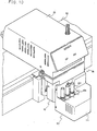
- the apparatus generally comprises a work unit 80 and a console unit 90.
- the console unit 90 includes a magnetic tape device 92, a floppy disc device 93, a key board 94 provided with a number of function keys and ten keys thereon, a monitoring unit 95 and a computer unit 91.
- Image information to be cut or drawn and control instructions are stored either in the magnetic tape or in a floppy disc, in the form of digital signals. Additional control instructions for work unit 80 are inputted through the key board.
- the computer unit 91 provided in the console unit 90 processes the image information on the basis of the control instructions, to output necessary control signals to the work unit 80.
- Selection which of the magnetic tape or floppy disc should be used is determined on the basis of quantity of information to be stored. That is, when a large quantity of mask information and control instruction is to be stored, the magnetic tape is selected, and to the contrary, when a relatively small quantity thereof, e.g. to the extent of one megabyte, is to be stored, the floppy disc is selected.
- the work unit 80 is electrically connected with the console unit 90 and is controlled by the output signals from the computer unit 91.
- the work unit 80 comprises a base frame 86, a drawing/cutting table 81 placed on the base frame, a first carriage 82 slidably movable along the table surface in the Y-direction, a second carriage 83 slidably movable along the first carriage in the X-direction, and a receiving station 84 to which both a cutter unit 10 and a drawing pen holder 101 is mounted.
- the carriages 82 and 83 is driven by motors (not shown) contained within the table 81 and a housing 85, respectively.
- the motors are controlled by the signals outputted from the computer unit 91, by which the receiving station 84 is moved in the X-and Y-directions, so that a desired image pattern is traced on the film material either by a cutter blade on the cutter unit 10 or by a drawing pen on the drawing pen holder 101.
- the table 81 includes suction elements (not shown) for fixedly holding a film material, e.g. a drafting paper, a mask film or the like, on the upper surface thereof.
- a film material e.g. a drafting paper, a mask film or the like
- a rotary encoder (not shown) is provided, by which a travel quantity of the respective carriages in the X-and Y-directions is measured to output to the computer unit 91, respectively.
- both the cutter unit and the drawing unit are fixedly mounted to the receiving station 84 of the second carriage 83.
- the cutter unit 10 includes a cutter blade provided at the lowermost part thereof, and the drawing unit 101 includes drawing pens thereon, both of the cutter blade and drawing pens are movable in the vertical direction relative to the upper surface of the film material, on which detailed discussions are given herebelow.
- FIG. 1 and 2 together with Figure 11, which show a structure of the cutter unit 10 in more detail, there provided is a mask film 4 which is fixedly mounted on the table 81 by the suction element.
- the cutter unit 10 is provided in such a manner as to be able to travel along the X-and Y-directions, by means of the carriages 82 and 83.
- the cutter unit 10 is mounted on the receiving station 84 which includes a supporting member 12. Also, a drawing unit 101 is mounted adjacent to the cutter unit 10 for carrying different drawing pens, e.g. a hollow pen, a ball point pen, a scriber or the like, for different purposes, but the drawing of the drawing unit 101 is omitted in Figures 1 and 2.
- drawing pens e.g. a hollow pen, a ball point pen, a scriber or the like
- the supporting member 12 is provided with a bracket 14 having bearings 16 through which a hollow shaft 18 is rotatably supported.
- the hollow shaft 18 has a flange 20 fixed to its lower end portion by means of screws 22, and has a gear 24 and a. disc 26 at its upper end portion, which function as a double nut.
- the disc 24 and flange 20 define the displacement of the hollow shaft 18 with respect to the bracket 14.
- the disc 26 is provided with a ring-shaped index rotor 28 at its periphery, which is to measure an origin for controlling the rotation of the hollow shaft 18.
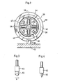
- the index rotor 28 has an index line 30 drawn thereon, as shown typically in Figure 2. When the index line 30 passes through a detector 32 fixed to the supporting member 12, it is measured so that a starting point is determined for counting the number of pulses outputted from a rotary encoder 70 attached to a motor 64 for rotating the hollow shaft 18.
- the reference numerals 34 and 36 denote an upper bearing and a lower bearing fixed to the disc 26 and the flange 20, respectively.
- the upper bearing 34 is provided with four roller carriers in a crosslike state on which rollers 38 are carried.
- the lower bearing 38 is provided with rollers 40 in the same manner.
- the rollers 38 and 40 support a main shaft 42 extending through the hollow shaft 18 in such a manner as to be vertically movable along the inside wall thereof and rotate in accordance with the rotation thereof.
- the reference numeral 46 denotes a spring provided between a disc plates 44 and 26 in such a manner as to bias the main shaft 42 and the disc plate 44 upward.
- the main shaft 42 is provided with a cutter holder 52 having a cutter blade 50 through a socket 48 at its lower terminating end, and is rotatably connected to a plate member 56 through a bearing 54, which the plate member is caused to move up and down in the manner described above.
- the bearing 54 comprises a self-aligning type.
- the plate member 56 is provided with an actuator 58, which is opposed to a core 62 fixed to a bracket 60 projecting from the supporting member 12.
- the actuator 58 is biased downward, wherein the biasing power is controlled by adjusting the applied voltage.
- the unitary assembly of the core 62 and actuator 58 will be referred to as linear motor.
- the motor 64 for rotation of the cutter blade is provided in place on the supporting member 12, and the driving shaft thereof is provided with a gear 66, to which the gear 24 of the hollow shaft 18 is connected through a timing belt 68.
- the hollow shaft 18 (accordingly, the main shaft 42) is rotated by the motor 64 by means of the timing belt.
- the motor 64 is provided with the rotary encoder 70, which outputs a number of pulses in proportion to the rotations thereof so as to control the rotation of the motor 64 by reference to the starting point decided by measuring the index line 30 on the index rotor 28 which passes through the detector 32. In this way, the cutter blade 50 is caused to manipulate as desired.
- the plate member 56 is provided with a position detecting device for detecting the position taken by the main shaft 42 with respect to the mask film 4 so as to control the speed at which the main shaft 42 descends.
- the position detecting device comprises a slitted plate 72 including a slit 74 and extending upward from plate member 56, and a set of a light source and an optical receiptor 76.
- the slit 74 is located so as to come into alignment with the optical axis of the set of the light source and receiptor 76 when the cutter blade descends up to a point immediately above the mask film 4 placed on the table. In this case, the position detecting device outputs a signal, thereby slowing down the descending speed of the cutter blade 50.
- the cutter blade 50 is made of hard material such as diamond, and is shaped as shown in Figures 3 and 4, wherein Figure 3 shows a front view in the moving direction A, and Figure 4 shows a side view thereof.
- a cutting mat e.g. of soft vinyle chloride (not shown) is preferably laid under the mask film so as to keep the edge of the cutter blade 50 away from the surface of the table 10.
- the mask film is fastened to the cutting mat by means of an appropriate measure, e.g. a suc tion element or an adhesive tape.
- the drawing unit 101 is mounted in front of the cutter unit 10.
- the drawing unit 101 includes three sets of pen station 105, to which desired drawing pens 103 are mounted as necessary.
- Each pen station 105 comprises a housing 111, bracket 109 fixedly mounted in the housing, a holder 107 movably provided on the bracket for holding a drawing pen 103 vertically thereon and a linear motor having substantially the same structure as that in the cutter unit.
- the linear motor comprises an actuator 113 and a core 115 which is opposed the actuator. Similarly to that in the cutter unit 10, thg actuator 113 is biased downward, when voltage is impressed, wherein the biasing power thereof is controlled by adjusting the voltage applied thereto.
- the holder 107 is normally biased upward by means of a spring 117 provided thereto, so as to raise a drawing pen 103 from a film material when it rests.
- the mask film 4 comprises a transparent substratum 8 and an opaque peeling layer 9, which the peeling layer of a desired image pattern is cut along its profile and - peeled therefrom.
- a mask film as above is commercially supplied as "CADPEEL” by Dainippon Screen Mfg. Co., Ltd.
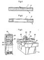
- the cutter blade 50 When cutting a desired mask image pattern, the cutter blade 50 may penetrate slightly into the substratum 8 beyond the opaque peeling layer 50, as shown in Figure 5.
- Figure 6 shows the mask film 4 having a positioning hole in which a registering pin fits.
- the depth of the cut is controlled- by increasing the voltage applied to the linear motor. More particularly, when only the opaque peeling layer of a desired image pattern is cut out of the mask film, the voltage is adjusted to be relatively low, thereby causing the cutter blade 50 to touch the mask film softly to the extent that it penetrates into the peeling layer 9 but does not deeply penetrate into the transparent substratum 8.
- the positioning hole is to be made, relatively high voltage is impressed to the linear motor so as to enable the cutter blade 50 to penetrate through the substratum 8.
- the piercing of the positioning holes can be carried out before, after or during the cutting of the desired image patterns in the peeling layer.
- the applied voltage is previously determined in accordance with the characteristics of the linear motor, the weight of the cutter unit, the strength of the biasing spring 46 and the quality of the mask film so as to secure an adequate pressure with which the cutter blade 50 touches the mask film.
- Control of the depth of cut may, of course, be done by adjusting amperage applied either to the linear motor of the cutting unit or to that of the drawing unit.
- the control is done by adjusting both the voltage and the amperage applied thereto.
- the cutter unit 10 is caused to move so as to enable the cutter blade 50 to manipulate along the outline of the desired image pattern, during which the cutter blade 50 is rotated in a direction corresponding to a moving direction of the cutter unit 10 by controlling the motor 64.
- Both the mask pattern and the positioning holes are cut by the same cutter blade 50 of a single apparatus on only one process by adjusting voltage and/or amperage applied to the linear motor. This secures the precise relative positioning between the desired mask patterns and positioning holes on the mask film, and accordingly, when the mask film is superposed on an original to be masked, the precise positioning relative to the original is secured.
- a block copy or negative film is placed on an appropriate coordinate apparatus (hereinafter referred to merely as digitizer), e.g. "Backlighting Digitizer FG-II BL” manufactured by Dainippon Screen Mfg. Co., Ltd., by which the desired image pattern information is obtained and stored either in the magnetic tape or in the floppy disc as necessary.
- digitizer e.g. "Backlighting Digitizer FG-II BL" manufactured by Dainippon Screen Mfg. Co., Ltd.
- the image pattern information involves one concerning the positioning holes and one concerning the mask image pattern.
- a "positioning hole cutting command” is inputted, and then coordinate values of the desired positioning holes are measured on the digitizer, and function commands for desired positioning holes, which represent line, arc, ellipse, circle, or the like, are selected from a menue table thereon.
- These commands and coordinated values are stored either in the magnetic tape or in the floppy disc.
- a film material e.g. mask film "CADPEEL” or drawing sheet
- CADPEEL CADPEEL
- drawing sheet a film material
- the computer unit 91 In response to the "positioning hole command”, the computer unit 91 outputs a control signal for controlling an offset pressure of the cutter unit 10 against the film material 4. As mentioned above, the offset pressure is controlled, e.g. at 200 gf. While, in response to the "mask-cut command", the computer unit outputs a control signal for controlling an offset pressure of the cutter blade, e.g. at 20 gf.
- the computer unit 91 outputs control signals for controlling the direction of the cutter blade 50 on the cutter unit as well as the movement of the cutter unit in the X-and Y-directions.
- the desired positioning holes and mask image patterns are cut by the cutter blade.
- An operator removes the thus cut area of the positioning holes and peels the opaque layer corresponding to the desired image pattern, whereby a desired mask film as shown in Figure 8 is obtained.
- a hatched area denotes an opaque one, by which undesired images of the original are masked.
- a reference numeral 5 denotes a transparent area, where the opaque layer is peeled from the film material, which precisely corresponds to the outer contour of the desired image to be exposed as shown in Figure 7 and through which only the desired image is exposed on a photosensitive material, e.g. placed on a focal plane of a process camera.
- a reference numerals 6 and 7 denote positioning holes having a different shape from each other, where both the opaque layer and the transparent layer are removed to fit the registering pins thereinto.
- the left positioning hole 6 is formed into a circle which precisely corresponding to the shape of the corresponding registering pin.
- the right positioning pin 7 is formed into a slot extending along the adjacent edge of the film material, by which fitting of the corresponding registering pin thereinto is easily carried out.
- the positioning holes can be formed any position on the film material so as to be adaptable for any specific pin-and-punch system.
- an original to be reproduced is positioned, e.g. on an original holder of a process camera, by fitting the registering pins fixed on the holder into the positioning holes provided on the original.
- "OP-COLOR" model CP-4850 supplied from Mitsubishi Paper Mills Ltd. as such a process camera as mentioned above.
- the mask film thus obtained is superposed. onto the original by fitting the registering pins into the positioning holes thereof in the same manner as above.
- Both the original and the mask film are closely pressed against the original holder, e.g. by a transparent pressure plate, by which only the desired image 1 on the original is reproduced on a photosensitive material placed on the focal plane of the camera.
- an original or a rough sketch of a desired image is placed on a digitizer.
- An operator inputs desired coordinate values of the image and appropriate function commands which represent appropriate line figures, e.g. line, arc, ellipse, circle or the like, by simulating the image on an appropriate monitoring device.
- a selection commands for designating an appropriate drawing pen among those held on the drawing unit are also inputted in accordance with a purpose of line drawing.
- the image pattern data thus inputted is stored either in the magnetic tape or in the floppy disc.
- an appropriate drawing sheet is placed on the work table 81, which is fixedly held thereon by means of a suction element.
- the aforementioned image pattern data are processed by the computer unit 91 of the console unit 90.
- the computer unit In response to the selection command, the computer unit outputs a designating signal for designating an appropriate drawing pen and a control signal for controlling an offset pressure and travelling speed in X-and Y-directions adaptable for thus designated drawing pen.
- the drawing pen On the basis of the output signals, the drawing pen is controlled, to draw a desired image on the drawing sheet.
Landscapes
- Life Sciences & Earth Sciences (AREA)
- Forests & Forestry (AREA)
- Engineering & Computer Science (AREA)
- Mechanical Engineering (AREA)
- Physics & Mathematics (AREA)
- General Physics & Mathematics (AREA)
- Preparing Plates And Mask In Photomechanical Process (AREA)
- Control Of Cutting Processes (AREA)
Applications Claiming Priority (2)
| Application Number | Priority Date | Filing Date | Title |
|---|---|---|---|
| JP61261521A JPS63115170A (ja) | 1986-10-31 | 1986-10-31 | カツテイングヘツドを備えた自動描画機 |
| JP261521/86 | 1986-10-31 |
Publications (2)
| Publication Number | Publication Date |
|---|---|
| EP0265957A2 true EP0265957A2 (fr) | 1988-05-04 |
| EP0265957A3 EP0265957A3 (fr) | 1990-04-18 |
Family
ID=17363057
Family Applications (1)
| Application Number | Title | Priority Date | Filing Date |
|---|---|---|---|
| EP87115932A Withdrawn EP0265957A3 (fr) | 1986-10-31 | 1987-10-29 | Appareil pour la réalisation automatique de trous de position dans un film |
Country Status (3)
| Country | Link |
|---|---|
| US (1) | US4825555A (fr) |
| EP (1) | EP0265957A3 (fr) |
| JP (1) | JPS63115170A (fr) |
Cited By (3)
| Publication number | Priority date | Publication date | Assignee | Title |
|---|---|---|---|---|
| EP0464625A3 (en) * | 1990-06-29 | 1992-05-20 | Alberto Peron | Cutting head for sheet-like products, particularly fabrics for the clothing industry |
| EP0348655A3 (fr) * | 1988-07-01 | 1992-05-20 | Investronica S.A. | Système d'entraínement pour instrument de marquage d'une machine à dessiner ou similaire |
| IT202300008697A1 (it) * | 2023-05-03 | 2024-11-03 | Orox Group S R L | Testa di taglio migliorata per un’apparecchiatura di taglio per tessuti e relativa apparecchiatura di taglio |
Families Citing this family (17)
| Publication number | Priority date | Publication date | Assignee | Title |
|---|---|---|---|---|
| JPH0761759B2 (ja) * | 1988-02-05 | 1995-07-05 | 大日本スクリーン製造株式会社 | 自動製図機の描画具駆動装置 |
| DE4005292A1 (de) * | 1990-02-20 | 1991-08-22 | Zeiss Carl Fa | Koordinatenmessgeraet |
| JP3638808B2 (ja) * | 1999-01-11 | 2005-04-13 | 株式会社ベルデックス | スクライブ装置 |
| US6427357B1 (en) * | 1999-08-13 | 2002-08-06 | Thomas W. Piper | Spindle mounted marking device for CNC machines |
| US20030221470A1 (en) * | 2002-05-30 | 2003-12-04 | Gunther Siegel | Apparatus for writing in metal |
| US20060112801A1 (en) * | 2002-09-18 | 2006-06-01 | Eric Ganci | Method and device for cutting masks for glueing coverings |
| FR2844470B1 (fr) * | 2002-09-18 | 2005-05-20 | Eric Ganci | Procede et dispositif de fabrication de masques de marouflage et masques obtenus |
| US6826840B1 (en) * | 2003-06-16 | 2004-12-07 | Micro Processing Technology, Inc. | Semiconductor wafer scribing system |
| US20070227332A1 (en) * | 2004-11-15 | 2007-10-04 | Xyron, Inc. | Automatic pattern making apparatus |
| EP1830988B1 (fr) * | 2004-11-15 | 2010-10-13 | Xyron, Inc. | Appareil automatique de fabrication de patrons |
| US7165331B1 (en) * | 2005-05-24 | 2007-01-23 | Micro Processing Technology, Inc. | Apparatus and method for scribing a semiconductor wafer while controlling scribing forces |
| JP4822448B2 (ja) * | 2007-09-12 | 2011-11-24 | 有限会社緑のマーケット | ラベル |
| US8615888B2 (en) * | 2009-06-30 | 2013-12-31 | Dexter-Russell, Inc. | Impaired grip knife |
| US9782788B2 (en) * | 2014-04-02 | 2017-10-10 | The Boeing Company | Method and system for forming masks |
| CN105619076A (zh) * | 2014-10-28 | 2016-06-01 | 富鼎电子科技(嘉善)有限公司 | 复合加工装置 |
| JP2018171669A (ja) * | 2017-03-31 | 2018-11-08 | ブラザー工業株式会社 | 切断装置 |
| CN115620975A (zh) * | 2021-07-16 | 2023-01-17 | 东莞令特电子有限公司 | 用于创建穿过金属氧化物变阻器涂层的开口的设备和方法 |
Family Cites Families (11)
| Publication number | Priority date | Publication date | Assignee | Title |
|---|---|---|---|---|
| US3158936A (en) * | 1961-11-13 | 1964-12-01 | Ancraft Products Co | Layout machine scribe |
| US3339279A (en) * | 1964-07-17 | 1967-09-05 | Robert H Sovar | Hollow engraving point and holder for engraving coated transparent sheets |
| US3519905A (en) * | 1966-08-26 | 1970-07-07 | Universal Drafting Machine Cor | Numerically controlled x-y servomechanisms for a drafting machine including secondary storage of permanent information |
| NO131870C (fr) * | 1970-10-12 | 1975-08-20 | Kongsberg Vapenfab As | |
| US4324047A (en) * | 1978-08-07 | 1982-04-13 | Xynetics, Inc. | Universal high speed holder |
| US4346392A (en) * | 1979-04-12 | 1982-08-24 | Mutoh Industry Ltd. | Plotting head for use in drawing machine |
| GB2136332B (en) * | 1983-01-21 | 1986-09-03 | Protocol Eng Ltd | Improvements in or relating to computer controlled tools for the production of graphic material for use in colour printing or like processes |
| US4512079A (en) * | 1983-07-21 | 1985-04-23 | Gerber Garment Technology, Inc. | Method and apparatus for indexing sheet material |
| US4635365A (en) * | 1983-09-09 | 1987-01-13 | Dainippon Screen Seizo Kabushiki Kaisha | Coordinate plotter with automatic punching device |
| US4709483A (en) * | 1984-03-14 | 1987-12-01 | Wing Aero | Glass cutting device |
| US4624169A (en) * | 1985-04-08 | 1986-11-25 | Aerochem, Inc. | Apparatus for automated cutting of thin films |
-
1986
- 1986-10-31 JP JP61261521A patent/JPS63115170A/ja active Granted
-
1987
- 1987-10-29 EP EP87115932A patent/EP0265957A3/fr not_active Withdrawn
- 1987-10-29 US US07/114,664 patent/US4825555A/en not_active Expired - Fee Related
Cited By (3)
| Publication number | Priority date | Publication date | Assignee | Title |
|---|---|---|---|---|
| EP0348655A3 (fr) * | 1988-07-01 | 1992-05-20 | Investronica S.A. | Système d'entraínement pour instrument de marquage d'une machine à dessiner ou similaire |
| EP0464625A3 (en) * | 1990-06-29 | 1992-05-20 | Alberto Peron | Cutting head for sheet-like products, particularly fabrics for the clothing industry |
| IT202300008697A1 (it) * | 2023-05-03 | 2024-11-03 | Orox Group S R L | Testa di taglio migliorata per un’apparecchiatura di taglio per tessuti e relativa apparecchiatura di taglio |
Also Published As
| Publication number | Publication date |
|---|---|
| JPH0340374B2 (fr) | 1991-06-18 |
| JPS63115170A (ja) | 1988-05-19 |
| EP0265957A3 (fr) | 1990-04-18 |
| US4825555A (en) | 1989-05-02 |
Similar Documents
| Publication | Publication Date | Title |
|---|---|---|
| US4825555A (en) | Apparatus for automatic forming on a film material of both a mask film pattern and a positioning hole | |
| US20140182463A1 (en) | Cutting data generator, cutting apparatus and non-transitory computer-readable medium storing cutting data generating program | |
| US3238624A (en) | Printed circuit layout machine | |
| US5495803A (en) | Method of forming a photomask for a printing plate with an ink jet | |
| US4933876A (en) | System of operating an automatic plotter | |
| US5139373A (en) | Optical lens pattern making system and method | |
| US20140182432A1 (en) | Cutting data generator, cutting apparatus and non-transitory computer-readable medium storing cutting data generating program | |
| CN110696093A (zh) | Ccd自动定位模切机 | |
| US3463041A (en) | Picture mat cutter | |
| US4738029A (en) | Numerically or manually controlled moving carriage drafting machine | |
| GB2136332A (en) | Improvements in or Relating to Computer Controlled Tools for the Production of Graphic Material for Use in Colour Printing or Like Processes | |
| GB2046928A (en) | Photodrafting | |
| US4711035A (en) | Method and apparatus for making a pattern for a lens opening in an eyeglass frame | |
| US3613501A (en) | Method of and apparatus for use in producing a three-dimensional model of a piece of terrain | |
| KR960006833B1 (ko) | 프린트 기판의 가공 방법 | |
| JP2828475B2 (ja) | 記録装置用カッターの上下装置 | |
| JPH058596A (ja) | 多機能彫刻機 | |
| JPH1110595A (ja) | サインメーカーにおける先当てツールの刃先突出量調整機構 | |
| JP3062354B2 (ja) | 用紙駆動型製図機の駆動方法と用紙駆動型製図機 | |
| JPH0238285Y2 (fr) | ||
| JP2526613Y2 (ja) | 載置型毛筆プロッタ | |
| JPS59206837A (ja) | 原稿の光電的スキヤンによる複写のため原稿のトリミング像を決定する装置 | |
| US3927586A (en) | Microfiche deleter apparatus | |
| WHIPPLE et al. | Microcircuit negative cutter(Precision surface cutter for screen circuit negatives and other microcircuits)[Patent] | |
| JPH03266699A (ja) | 毛筆プロッタの駆動制御方法 |
Legal Events
| Date | Code | Title | Description |
|---|---|---|---|
| PUAI | Public reference made under article 153(3) epc to a published international application that has entered the european phase |
Free format text: ORIGINAL CODE: 0009012 |
|
| AK | Designated contracting states |
Kind code of ref document: A2 Designated state(s): DE FR GB |
|
| PUAL | Search report despatched |
Free format text: ORIGINAL CODE: 0009013 |
|
| AK | Designated contracting states |
Kind code of ref document: A3 Designated state(s): DE FR GB |
|
| 17P | Request for examination filed |
Effective date: 19900522 |
|
| 17Q | First examination report despatched |
Effective date: 19921214 |
|
| STAA | Information on the status of an ep patent application or granted ep patent |
Free format text: STATUS: THE APPLICATION IS DEEMED TO BE WITHDRAWN |
|
| 18D | Application deemed to be withdrawn |
Effective date: 19930625 |
|
| RIN1 | Information on inventor provided before grant (corrected) |
Inventor name: HASHIMOTO, TAKEJI Inventor name: MURAYAMA, MINORU Inventor name: YAMAMOTO, TAKAHARU |