EP0266055B1 - Vorrichtung zum Verschliessen des Abstichloches eines metallurgischen Gefässes - Google Patents
Vorrichtung zum Verschliessen des Abstichloches eines metallurgischen Gefässes Download PDFInfo
- Publication number
- EP0266055B1 EP0266055B1 EP87308457A EP87308457A EP0266055B1 EP 0266055 B1 EP0266055 B1 EP 0266055B1 EP 87308457 A EP87308457 A EP 87308457A EP 87308457 A EP87308457 A EP 87308457A EP 0266055 B1 EP0266055 B1 EP 0266055B1
- Authority
- EP
- European Patent Office
- Prior art keywords
- closure member
- taphole
- core
- plug
- metal
- Prior art date
- Legal status (The legal status is an assumption and is not a legal conclusion. Google has not performed a legal analysis and makes no representation as to the accuracy of the status listed.)
- Expired - Lifetime
Links
- 229910052751 metal Inorganic materials 0.000 claims abstract description 22
- 239000002184 metal Substances 0.000 claims abstract description 22
- 239000002893 slag Substances 0.000 claims abstract description 19
- 230000000694 effects Effects 0.000 claims abstract description 5
- 239000000463 material Substances 0.000 claims description 15
- 239000010410 layer Substances 0.000 claims description 13
- 239000000203 mixture Substances 0.000 claims description 9
- 239000007788 liquid Substances 0.000 claims description 7
- CPLXHLVBOLITMK-UHFFFAOYSA-N Magnesium oxide Chemical compound [Mg]=O CPLXHLVBOLITMK-UHFFFAOYSA-N 0.000 claims description 5
- 238000000034 method Methods 0.000 claims description 5
- VYPSYNLAJGMNEJ-UHFFFAOYSA-N Silicium dioxide Chemical compound O=[Si]=O VYPSYNLAJGMNEJ-UHFFFAOYSA-N 0.000 claims description 4
- 239000002344 surface layer Substances 0.000 claims description 4
- 239000010455 vermiculite Substances 0.000 claims description 4
- 229910052902 vermiculite Inorganic materials 0.000 claims description 4
- 235000019354 vermiculite Nutrition 0.000 claims description 4
- 235000008733 Citrus aurantifolia Nutrition 0.000 claims description 2
- CDBYLPFSWZWCQE-UHFFFAOYSA-L Sodium Carbonate Chemical compound [Na+].[Na+].[O-]C([O-])=O CDBYLPFSWZWCQE-UHFFFAOYSA-L 0.000 claims description 2
- 239000004115 Sodium Silicate Substances 0.000 claims description 2
- 235000011941 Tilia x europaea Nutrition 0.000 claims description 2
- 239000004571 lime Substances 0.000 claims description 2
- 239000000395 magnesium oxide Substances 0.000 claims description 2
- 239000000377 silicon dioxide Substances 0.000 claims description 2
- NTHWMYGWWRZVTN-UHFFFAOYSA-N sodium silicate Chemical compound [Na+].[Na+].[O-][Si]([O-])=O NTHWMYGWWRZVTN-UHFFFAOYSA-N 0.000 claims description 2
- 229910052911 sodium silicate Inorganic materials 0.000 claims description 2
- 239000006260 foam Substances 0.000 claims 1
- 238000010079 rubber tapping Methods 0.000 description 5
- 239000011230 binding agent Substances 0.000 description 4
- 239000000126 substance Substances 0.000 description 4
- OKTJSMMVPCPJKN-UHFFFAOYSA-N Carbon Chemical compound [C] OKTJSMMVPCPJKN-UHFFFAOYSA-N 0.000 description 2
- 229910000831 Steel Inorganic materials 0.000 description 2
- 239000010439 graphite Substances 0.000 description 2
- 229910002804 graphite Inorganic materials 0.000 description 2
- 238000004519 manufacturing process Methods 0.000 description 2
- 239000011347 resin Substances 0.000 description 2
- 229920005989 resin Polymers 0.000 description 2
- 239000010959 steel Substances 0.000 description 2
- 238000007792 addition Methods 0.000 description 1
- 239000000654 additive Substances 0.000 description 1
- RHZUVFJBSILHOK-UHFFFAOYSA-N anthracen-1-ylmethanolate Chemical compound C1=CC=C2C=C3C(C[O-])=CC=CC3=CC2=C1 RHZUVFJBSILHOK-UHFFFAOYSA-N 0.000 description 1
- 239000003830 anthracite Substances 0.000 description 1
- QVGXLLKOCUKJST-UHFFFAOYSA-N atomic oxygen Chemical compound [O] QVGXLLKOCUKJST-UHFFFAOYSA-N 0.000 description 1
- 238000009844 basic oxygen steelmaking Methods 0.000 description 1
- 239000007767 bonding agent Substances 0.000 description 1
- 239000003575 carbonaceous material Substances 0.000 description 1
- 230000015556 catabolic process Effects 0.000 description 1
- 239000007789 gas Substances 0.000 description 1
- 239000011521 glass Substances 0.000 description 1
- 238000010438 heat treatment Methods 0.000 description 1
- 238000010348 incorporation Methods 0.000 description 1
- 238000003780 insertion Methods 0.000 description 1
- 230000037431 insertion Effects 0.000 description 1
- 239000001301 oxygen Substances 0.000 description 1
- 229910052760 oxygen Inorganic materials 0.000 description 1
- 239000004033 plastic Substances 0.000 description 1
- 230000035484 reaction time Effects 0.000 description 1
- 239000011819 refractory material Substances 0.000 description 1
- 230000000284 resting effect Effects 0.000 description 1
- 239000007787 solid Substances 0.000 description 1
Images

Classifications
-
- F—MECHANICAL ENGINEERING; LIGHTING; HEATING; WEAPONS; BLASTING
- F27—FURNACES; KILNS; OVENS; RETORTS
- F27D—DETAILS OR ACCESSORIES OF FURNACES, KILNS, OVENS OR RETORTS, IN SO FAR AS THEY ARE OF KINDS OCCURRING IN MORE THAN ONE KIND OF FURNACE
- F27D3/00—Charging; Discharging; Manipulation of charge
- F27D3/15—Tapping equipment; Equipment for removing or retaining slag
- F27D3/1509—Tapping equipment
- F27D3/1536—Devices for plugging tap holes, e.g. plugs stoppers
-
- C—CHEMISTRY; METALLURGY
- C21—METALLURGY OF IRON
- C21C—PROCESSING OF PIG-IRON, e.g. REFINING, MANUFACTURE OF WROUGHT-IRON OR STEEL; TREATMENT IN MOLTEN STATE OF FERROUS ALLOYS
- C21C5/00—Manufacture of carbon-steel, e.g. plain mild steel, medium carbon steel or cast steel or stainless steel
- C21C5/28—Manufacture of steel in the converter
- C21C5/42—Constructional features of converters
- C21C5/46—Details or accessories
- C21C5/4653—Tapholes; Opening or plugging thereof
Definitions
- This invention relates to closures for metallurgical vessel pouring apertures and more particularly, although not exclusively, to closure members for tapholes of metal producing or processing vessels such as a basic oxygen stelmaking (BOS) vessel.
- BOS basic oxygen stelmaking
- a problem in the tapping of BOS vessels is that, as the vessels are tilted towards the tapping position, an initial flow of slag will leave the vessel by the taphole, causing difficulties in disposal, prior to the metal contained in the BOS vessel being tapped into the waiting receptacle as it reaches the level of the taphole.
- a number of systems have been devised in which a plugging device is inserted or fitted to the outside (cold end) of the taphole to prevent slag egress but when they are used there is a possibility that the taphole will initially fill with slag which will not be entirely displaced by metal when tapping begins.
- GB-A-2091396 discloses a taphole plug preferably vacuum formed to dimensions and shape such that it will fit the taphole tightly, for a basic oxygen steel making furnace, the plug comprising a resin, preferably a heat-curable resin, as a thermally degradable bonding agent, and vermiculite as a temperature reactive component which swells upon heating thus ensuring total disintegration of the plug.
- a closure member for a taphole or closure of a metal and slag containing vessel comprising a plug including a temperature reactive component rapidly expandable when subjected to heat, and characterised by a component softening under the effect of heat whereby, in use, the closure member expands and fits the taphole to form a block thereto.
- the closure member may be a homogeneous body carrying the two components hereinabove specified, or alternatively, may be layered or the two components otherwise segregated at least in part.
- a closure member for a taphole or closure of a metal and slag containing vessel characterised by a plug including a temperature reactive core member rapidly expandable when subjected to heat, and an outer surface layer surrounding and encasing the core and being of a material softening under the effect of heat and capable of stretching to accommodate the inner expanding core.
- the core may contain a component which expands and/or gives off a gas when heated such that the core then expands in a foam-like manner, and may be mixed with a component softening to form a viscous liquid.
- the outer layer may likewise be composed of material forming a viscous liquid when heated, and can be of the same substance as the viscous liquid form of material used in the core.
- a method of utilising a closure member as hereinbefore defined to control the pouring of metal from a tiltable vessel containing molten metal and slag and having a taphole characterised by inserting a loosely fitting closure member into the inner end of the taphole; allowing the closure member to heat and rapidly expand to fit tightly within the taphole; tilting the vessel so that the slag layer moves past the taphole; and holding the vessel tilted with molten metal alongside the taphole until the metal breaks through the closure member and is poured from the taphole.
- the invention enables the provision of a closure for the taphole of the vessel at its inner (hot end) to prevent slag from leaving the same prior to the tapping of metal therefrom.
- a plug 5 in accordance with the invention as a closure at the inner end of the taphole prevents the egress of slag through the taphole.
- the plug 5 comprises, as previously mentioned, a core 6 containing a component that expands and may give off a gass when heated, and may typically be comprised of vermiculite, which is a material which exfoliates and gives off steam at temperatures above 330°C.
- vermiculite which is a material which exfoliates and gives off steam at temperatures above 330°C.
- a second component that softens at a higher temperature (800°C to 1000°C) to form a viscous liquid binding the expanding vermiculite or forming material together.
- the plug also comprises an outler layer 7 surrounding and encasing the core which is composed of a material, again forming a viscous liquid at 800°C to 1000°C. This can be of the same substance as that used as a binder in the core 6.
- the outer layer 7 of the plug softens.
- this expands and inflates the softened outer layer (or skin) 7.
- the delay time between insertion of the plug and expansion depends upon the thickness of the of skin 7, with thinner skins giving shorter delay times.
- the softening temperature of the skin 7 can be controlled by choice of the chemical composition thereof.
- the plug has a surface layer or skin which is mush thicker at the ends 8 than elsewhere. This has been found to be a desirable characteristic in order to preserve the integrity of the skin. Thus, a thin skin at the ends would tend to soften and run off rapidly, leaving exposed core 6 which would then not inflate effectively.
- the plug Upon inflation of the core 6 so that it fills the taphole temporarily, slag is prevented from escaping through the taphole 4 when the vessel 1 is tilted through contact with the slag layer 2.
- the plug will only retain its mechanical strength for a few seconds before breaking down under the influence of the weight and heat in the steel resting upon it as the vessel is tilted beyond the slag layer to the underlying metal 3.
- the steel flows from the taphole into the receiving arrangement (not shown) disposed thereinbelow in the required manner.
- a typical plug comprises a core of the order of 160mm long x 54mm diameter coated with 6.5mm of skin on its curved surface and 35mm at the flat ends.
- the diameter of a plug should preferably not be less than 70% of the diameter of the hole it is required to fill and the closer the diameter of the plug is to the diameter of the hole the more tightly the plug will fill the hole.
- the preferred minimum diameter (d) of the plug's core can be calculated from the diameter of the hole (D) by using:
- the skin and core binder may comprise a soda/lime/silica mixture and sodium silicate, and typical composition of skin and core binder, which is based on powdered glass, is:
- the softening temperature of the skin and core binder can be increased by the use of additives, for example magnesia (MgO), to the mix at concentrations of up to or beyond 50% weight.
- MgO magnesia
- the skin in this case may remain brittle to higher temperatures and it may be necessary to increase the thickness of the skin to prevent heat reaching the core and starting inflation before the skin softens.
- the life of the plug, and its inflation time (delay times) can be varied by the incorporation of materials of different levels of conductivity, such as materials of high conductivity, in the mixes both for the core 6 and for the surface layer 7.
- materials of different levels of conductivity such as materials of high conductivity
- carbonaceous materials such as electrocalcined anthracite, electrocalcined graphite, and natural flake graphite to the skin and core can be used to decrease reaction times.
- an outer layer of material for example magnesia
- a chemical composition so chosen as to minimise any reaction between the component materials of the plug and the taphole refractories.
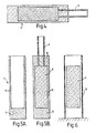
- the plug can incorporate a device such as a thick cardboard tube 9 as seen in Figure 4. This enables the plug 5 to be slipped onto the end of a pole (not shown) so that it can be pushed into position. When the plug is in place the outermost layer of the skin 7 softens almost immediately and makes the plug adhere to the inside of the taphole 4 and the pole can be withdrawn.
- a device such as a thick cardboard tube 9 as seen in Figure 4.
- FIG. 5A & 5B one method is to press the mix to make a solid end 11 and shell 12 of skin material which is subsequently filled with core mix 6 and topped off with a thick end skin 10 and fitted with a thick cardboard tube 9.
- a second method as seen in Figure 6 is to press the core 6 and when it has hardened place it centrally in a thin cardboard tube 13 which acts as an outer mould which is then filled with the skin material and a thick cardboard tube fitted as with Figure 5 (not shown).
- the thin cardboard outer tube 13 can be peeled off or the plug used with the thin cardboard remaining.
- the thin cardboard tube 13 that acts as the outer mould can be replaced by a plastic tube which need not be removed after manufacture and which breaks down very rapidly when subjected to heat.
Landscapes
- Engineering & Computer Science (AREA)
- Chemical & Material Sciences (AREA)
- Manufacturing & Machinery (AREA)
- Materials Engineering (AREA)
- Metallurgy (AREA)
- Organic Chemistry (AREA)
- Mechanical Engineering (AREA)
- General Engineering & Computer Science (AREA)
- Carbon Steel Or Casting Steel Manufacturing (AREA)
- Closures For Containers (AREA)
- Furnace Charging Or Discharging (AREA)
- Bipolar Transistors (AREA)
- Materials For Photolithography (AREA)
- Cartons (AREA)
- Treatment Of Steel In Its Molten State (AREA)
- Containers Opened By Tearing Frangible Portions (AREA)
- Manufacture Of Iron (AREA)
Claims (12)
- Verschlußstück (5) für ein Spundloch oder einen Spund (4) eines Metall und Schlacke enthaltenden Gießbehälter (Gießpfanne) (1); das Verschlußstück umfaßt einen Stopfen (5), der ein temperaturbetätigbares Teil enthält, das sich schnell dehnt, wenn es Wärme ausgesetzt wird, und das Verschlußstück ist gekennzeichnet durch ein Teil desselben, das unter der Einwirkung von Wärme erweicht, wodurch sich das Verschlußstück (5) bei Gebrauch ausdehnt und so in das Spundloch (4) paßt, daß es dieses fest verschließt.
- Verschlußstück (5) für ein Spundloch oder einen Spund (4) eines Metall und Schlacke enthaltenden Gefäßes (1), gekennzeichnet durch einen Stopfen (5), der ein temperaturbetätigtes Kernstück (6) umfaßt, das sich schnell dehnt, wenn es Wärme ausgesetzt wird, und durch eine äußere Mantelschicht (7), die den Kern umgibt, und einschließt und die aus einem Material besteht, das sich unter Wärmeeinwirkung erweicht und derart dehnbar ist, daß es sich dem inneren, sich dehnenden Kern (6) leicht anpaßt.
- Verschlußstück (5) nach Anspruch 2, dadurch gekennzeichnet, daß der Kern (6) einen Anteil enthält, der sich ausdehnt, wenn er erwärmt wird.
- Verschlußstück (5) nach Anspruch 2 oder 3, dadurch gekennzeichnet, daß der Kern (6) einen Anteil enthält, der ein Gas abgibt, wenn er erwärmt wird, so daß der Kern sich schaumartig ausdehnt.
- Verschlußstück (5) nach Anspruch 2, 3 oder 4, dadurch gekennzeichnet, daß der Kern (6) einen unter Wärme erweichenden Anteil enthält und dann eine zähe Flüssigkeit bildet.
- Verschlußstück (5) nach einem der Ansprüche 2 bis 5, dadurch gekennzeichnet, daß die Außenschicht (7) aus einem Material zusammengesetzt ist, die erwärmt eine zähe Flüssigkeit bildet.
- Verschlußstück (5) nach einem der Ansprüche 2 bis 6, dadurch gekennzeichnet, daß der Kern (6) Vermiculite beinhaltet.
- Verschlußstück (5) nach einem der Ansprüche 2 bis 7, dadurch gekennzeichnet, daß der Kern (6) eine Soda-Kalk-Sand-Mischung und Natriumsilikat enthält und die Außenschicht (7) mit einer Soda-Kalk-Sand-Mischung und Natriumsilikat zusammengesetzt ist.
- Verschlußstück (5) nach Anspruch 8, dadurch gekennzeichnet, daß der Kern (6) und die Außenschicht (7) Magnesia (MgO) enthalten.
- Verschlußstück (5) nach einem der vorstehenden Ansprüche, dadurch gekennzeichnet, daß der Stopfen (5) die Gestalt eines Zylinders mit parallelen Seiten hat.
- Verschlußstück (5) nach einem der vorstehenden Ansprüche, dadurch gekennzeichnet, daß der Stopfen (5) nicht erwärmt so angepaßt ist, daß er lose in das Spundloch oder den Spund (4) eines Metall und Schlacke enthaltenden Gefäßes (1) paßt.
- Verfahren zum Gebrauch eines Verschlußstückes nach einem der vorstehenden Ansprüche zur Steuerung des Metallabstiches aus einem schwenkbaren Gießgefäß, das geschmolzenes Metall und Schlacke enthält und ein Spundloch hat, gekennzeichnet durch das Einsetzen eines lose passenden Verschlußstückes in das innere Ende des Spundloches durch das Gestatten, daß sich das Verschlußstück erwärmt und schnell ausdehnt, um dicht in das Spundloch zu passen, durch das Kippen des Gefäßes, so daß die Schlacke sich an dem Spundloch vorbeibewegt, und durch das Gekippthalten des Gefäßes mit dem geschmolzenen Metall neben dem Spundloch bis das Metall durch das Verschlußstück bricht und aus dem Spundloch ausströmt.
Priority Applications (1)
| Application Number | Priority Date | Filing Date | Title |
|---|---|---|---|
| AT87308457T ATE62711T1 (de) | 1986-09-26 | 1987-09-24 | Vorrichtung zum verschliessen des abstichloches eines metallurgischen gefaesses. |
Applications Claiming Priority (2)
| Application Number | Priority Date | Filing Date | Title |
|---|---|---|---|
| GB868623204A GB8623204D0 (en) | 1986-09-26 | 1986-09-26 | Closures for vessel pouring apertures |
| GB8623204 | 1986-09-26 |
Publications (2)
| Publication Number | Publication Date |
|---|---|
| EP0266055A1 EP0266055A1 (de) | 1988-05-04 |
| EP0266055B1 true EP0266055B1 (de) | 1991-04-17 |
Family
ID=10604847
Family Applications (1)
| Application Number | Title | Priority Date | Filing Date |
|---|---|---|---|
| EP87308457A Expired - Lifetime EP0266055B1 (de) | 1986-09-26 | 1987-09-24 | Vorrichtung zum Verschliessen des Abstichloches eines metallurgischen Gefässes |
Country Status (6)
| Country | Link |
|---|---|
| US (1) | US4913404A (de) |
| EP (1) | EP0266055B1 (de) |
| AT (1) | ATE62711T1 (de) |
| DE (1) | DE3769433D1 (de) |
| ES (1) | ES2021369B3 (de) |
| GB (2) | GB8623204D0 (de) |
Families Citing this family (7)
| Publication number | Priority date | Publication date | Assignee | Title |
|---|---|---|---|---|
| GB2216638B (en) * | 1988-03-04 | 1992-01-02 | British Steel Plc | Closures for metallurgical vessel pouring apertures |
| AU625800B2 (en) * | 1988-12-01 | 1992-07-16 | Goricon Metallurgical Services Limited | Improvements relating to steel-making vessels |
| GB9222548D0 (en) * | 1992-10-27 | 1992-12-09 | Foseco Int | Metallurgical pouring vessels |
| DE19848004B4 (de) * | 1998-10-17 | 2006-10-12 | Stilkerieg, Berthold, Dipl.-Ing. | Vorrichtung zur Vermeidung von Kontamination des Abstichstahles durch Vorlaufschlacke bei einem kippbaren Konverter mit verbesserter Materialzusammensetzung |
| US6412672B1 (en) * | 2000-05-01 | 2002-07-02 | The Carmany Goup Incorporated | Ladle to tundish transfer to molten metal in the steelmaking process |
| US6630221B1 (en) * | 2000-07-21 | 2003-10-07 | Dexter Corporation | Monolithic expandable structures, methods of manufacture and composite structures |
| US7452585B1 (en) | 2000-07-21 | 2008-11-18 | Henkel Corporation | Monolithic structures, methods of manufacture and composite structures |
Family Cites Families (6)
| Publication number | Priority date | Publication date | Assignee | Title |
|---|---|---|---|---|
| IT1045699B (it) * | 1972-07-31 | 1980-06-10 | Centro Speriment Metallurg | Dispositivo per l otturazione del foro di colata in reattori per processi metallurgici |
| US4010936A (en) * | 1973-06-05 | 1977-03-08 | Aikoh Co., Ltd. | Process for tapping a steel-making converter |
| DE2549728C2 (de) * | 1975-11-06 | 1977-10-06 | Stahlwerke Peine-Salzgitter Ag, 3150 Peine | Vorrichtung zum Verschließen des Abstichloches eines Konverters |
| GB2091396B (en) * | 1981-01-17 | 1985-02-27 | London Scandinavian Metall | Thermally-degradable taphole plug |
| US4399986A (en) * | 1981-12-14 | 1983-08-23 | Collins William J | Device for plugging a taphole in a furnace |
| US4471950A (en) * | 1982-10-22 | 1984-09-18 | Labate M D | Expandable, consumable stopper plug for steel making and handling vessels |
-
1986
- 1986-09-26 GB GB868623204A patent/GB8623204D0/en active Pending
-
1987
- 1987-09-24 GB GB8722458A patent/GB2195752B/en not_active Expired - Fee Related
- 1987-09-24 DE DE8787308457T patent/DE3769433D1/de not_active Expired - Fee Related
- 1987-09-24 ES ES87308457T patent/ES2021369B3/es not_active Expired - Lifetime
- 1987-09-24 EP EP87308457A patent/EP0266055B1/de not_active Expired - Lifetime
- 1987-09-24 AT AT87308457T patent/ATE62711T1/de not_active IP Right Cessation
-
1989
- 1989-02-21 US US07/313,335 patent/US4913404A/en not_active Expired - Fee Related
Also Published As
| Publication number | Publication date |
|---|---|
| US4913404A (en) | 1990-04-03 |
| ATE62711T1 (de) | 1991-05-15 |
| ES2021369B3 (es) | 1991-11-01 |
| DE3769433D1 (de) | 1991-05-23 |
| GB2195752A (en) | 1988-04-13 |
| EP0266055A1 (de) | 1988-05-04 |
| GB2195752B (en) | 1990-06-20 |
| GB8623204D0 (en) | 1986-10-29 |
| GB8722458D0 (en) | 1987-10-28 |
Similar Documents
| Publication | Publication Date | Title |
|---|---|---|
| US4913404A (en) | Closures for metallurgical vessel pouring apertures | |
| KR20070033993A (ko) | 코드 와이어 | |
| MXPA04004454A (es) | Metodo y aparato para fundir metales. | |
| JPS58125659A (ja) | 溶融金属容器 | |
| KR870009965A (ko) | 슬라이드 게이트용 내화 성형체 | |
| EP0260735B1 (de) | Verschluss für das Abstichloch eines Stahlwerkskonverters und Verfahren zum Betreiben eines Stahlwerkskonverters | |
| KR20030081527A (ko) | 용융된 금속 내에 가스를 주입하는 내화 플러그 또는 내화벽돌 | |
| CA1269405A (en) | Refractory compositions | |
| EP0189258A2 (de) | Feuerfeste Zusammensetzung | |
| US3292662A (en) | Lance pipe for the injected oxygen in steel making | |
| JP4132278B2 (ja) | 誘導炉ラミング材 | |
| GB2216638A (en) | Closure for metallurgical vessel pouring aperture | |
| US5018709A (en) | Making a taphole | |
| US4162179A (en) | Refractory article and method of making the same | |
| JP3078701B2 (ja) | 冶金用容器の出鋼口閉塞用膨張性プラグ | |
| JP2587827Y2 (ja) | 転炉出鋼口用栓 | |
| EP0446252B1 (de) | Gefässe zur stahlherstellung | |
| US4135939A (en) | Refractory article and method of making the same | |
| JP3082990B2 (ja) | 膨張性プラグ | |
| JP2000302562A (ja) | 熱間煉瓦目地充填材 | |
| RU2000101173A (ru) | Способ внепечного нагрева жидкого металла в ковше и экзотермическая оболочковая проволока "экзо-про" для его осуществления | |
| Barker | Tundish Cover Layer Containing Flux Ingredients and Expandable Graphite | |
| JPH07260372A (ja) | 冶金用容器の出鋼口閉塞用膨張性プラグ | |
| Palumbo | The study of a magnesium wire feeding technique for the desulphurization of molten iron and liquid steel | |
| KR810000587B1 (ko) | 용융금속에 증발성 반응문을 도입하기 위한 장치 |
Legal Events
| Date | Code | Title | Description |
|---|---|---|---|
| PUAI | Public reference made under article 153(3) epc to a published international application that has entered the european phase |
Free format text: ORIGINAL CODE: 0009012 |
|
| AK | Designated contracting states |
Kind code of ref document: A1 Designated state(s): AT BE CH DE ES FR IT LI LU NL SE |
|
| RAP1 | Party data changed (applicant data changed or rights of an application transferred) |
Owner name: BRITISH STEEL PLC |
|
| 17P | Request for examination filed |
Effective date: 19881021 |
|
| 17Q | First examination report despatched |
Effective date: 19900112 |
|
| GRAA | (expected) grant |
Free format text: ORIGINAL CODE: 0009210 |
|
| AK | Designated contracting states |
Kind code of ref document: B1 Designated state(s): AT BE CH DE ES FR IT LI LU NL SE |
|
| REF | Corresponds to: |
Ref document number: 62711 Country of ref document: AT Date of ref document: 19910515 Kind code of ref document: T |
|
| ITF | It: translation for a ep patent filed | ||
| ET | Fr: translation filed | ||
| REF | Corresponds to: |
Ref document number: 3769433 Country of ref document: DE Date of ref document: 19910523 |
|
| PLBE | No opposition filed within time limit |
Free format text: ORIGINAL CODE: 0009261 |
|
| STAA | Information on the status of an ep patent application or granted ep patent |
Free format text: STATUS: NO OPPOSITION FILED WITHIN TIME LIMIT |
|
| 26N | No opposition filed | ||
| PGFP | Annual fee paid to national office [announced via postgrant information from national office to epo] |
Ref country code: CH Payment date: 19920814 Year of fee payment: 6 |
|
| PGFP | Annual fee paid to national office [announced via postgrant information from national office to epo] |
Ref country code: FR Payment date: 19930809 Year of fee payment: 7 |
|
| PGFP | Annual fee paid to national office [announced via postgrant information from national office to epo] |
Ref country code: AT Payment date: 19930810 Year of fee payment: 7 |
|
| PGFP | Annual fee paid to national office [announced via postgrant information from national office to epo] |
Ref country code: BE Payment date: 19930823 Year of fee payment: 7 |
|
| PGFP | Annual fee paid to national office [announced via postgrant information from national office to epo] |
Ref country code: LU Payment date: 19930903 Year of fee payment: 7 |
|
| PGFP | Annual fee paid to national office [announced via postgrant information from national office to epo] |
Ref country code: ES Payment date: 19930909 Year of fee payment: 7 |
|
| PG25 | Lapsed in a contracting state [announced via postgrant information from national office to epo] |
Ref country code: LI Effective date: 19930930 Ref country code: CH Effective date: 19930930 |
|
| EPTA | Lu: last paid annual fee | ||
| REG | Reference to a national code |
Ref country code: CH Ref legal event code: PL |
|
| PG25 | Lapsed in a contracting state [announced via postgrant information from national office to epo] |
Ref country code: LU Free format text: LAPSE BECAUSE OF NON-PAYMENT OF DUE FEES Effective date: 19940924 Ref country code: AT Effective date: 19940924 |
|
| PG25 | Lapsed in a contracting state [announced via postgrant information from national office to epo] |
Ref country code: ES Free format text: LAPSE BECAUSE OF EXPIRATION OF PROTECTION Effective date: 19940926 |
|
| PG25 | Lapsed in a contracting state [announced via postgrant information from national office to epo] |
Ref country code: BE Effective date: 19940930 |
|
| EAL | Se: european patent in force in sweden |
Ref document number: 87308457.8 |
|
| BERE | Be: lapsed |
Owner name: BRITISH STEEL P.L.C. Effective date: 19940930 |
|
| PG25 | Lapsed in a contracting state [announced via postgrant information from national office to epo] |
Ref country code: FR Effective date: 19950531 |
|
| REG | Reference to a national code |
Ref country code: FR Ref legal event code: ST |
|
| PGFP | Annual fee paid to national office [announced via postgrant information from national office to epo] |
Ref country code: SE Payment date: 19950814 Year of fee payment: 9 |
|
| PGFP | Annual fee paid to national office [announced via postgrant information from national office to epo] |
Ref country code: DE Payment date: 19950823 Year of fee payment: 9 |
|
| PG25 | Lapsed in a contracting state [announced via postgrant information from national office to epo] |
Ref country code: SE Effective date: 19960925 |
|
| PG25 | Lapsed in a contracting state [announced via postgrant information from national office to epo] |
Ref country code: DE Effective date: 19970603 |
|
| EUG | Se: european patent has lapsed |
Ref document number: 87308457.8 |
|
| REG | Reference to a national code |
Ref country code: ES Ref legal event code: FD2A Effective date: 19990601 |
|
| PGFP | Annual fee paid to national office [announced via postgrant information from national office to epo] |
Ref country code: NL Payment date: 19990819 Year of fee payment: 13 |
|
| PG25 | Lapsed in a contracting state [announced via postgrant information from national office to epo] |
Ref country code: NL Free format text: LAPSE BECAUSE OF NON-PAYMENT OF DUE FEES Effective date: 20010401 |
|
| NLV4 | Nl: lapsed or anulled due to non-payment of the annual fee |
Effective date: 20010401 |
|
| PG25 | Lapsed in a contracting state [announced via postgrant information from national office to epo] |
Ref country code: IT Free format text: LAPSE BECAUSE OF NON-PAYMENT OF DUE FEES;WARNING: LAPSES OF ITALIAN PATENTS WITH EFFECTIVE DATE BEFORE 2007 MAY HAVE OCCURRED AT ANY TIME BEFORE 2007. THE CORRECT EFFECTIVE DATE MAY BE DIFFERENT FROM THE ONE RECORDED. Effective date: 20050924 |