EP0266108A1 - Wärmeaustauscher - Google Patents
Wärmeaustauscher Download PDFInfo
- Publication number
- EP0266108A1 EP0266108A1 EP87309203A EP87309203A EP0266108A1 EP 0266108 A1 EP0266108 A1 EP 0266108A1 EP 87309203 A EP87309203 A EP 87309203A EP 87309203 A EP87309203 A EP 87309203A EP 0266108 A1 EP0266108 A1 EP 0266108A1
- Authority
- EP
- European Patent Office
- Prior art keywords
- heat exchanger
- side wall
- members
- end caps
- casing
- Prior art date
- Legal status (The legal status is an assumption and is not a legal conclusion. Google has not performed a legal analysis and makes no representation as to the accuracy of the status listed.)
- Withdrawn
Links
- 239000012530 fluid Substances 0.000 claims abstract description 21
- 238000005219 brazing Methods 0.000 claims description 10
- 238000000034 method Methods 0.000 claims description 4
- 229910000838 Al alloy Inorganic materials 0.000 claims description 3
- 239000000463 material Substances 0.000 abstract description 8
- 210000002105 tongue Anatomy 0.000 description 6
- WYTGDNHDOZPMIW-RCBQFDQVSA-N alstonine Natural products C1=CC2=C3C=CC=CC3=NC2=C2N1C[C@H]1[C@H](C)OC=C(C(=O)OC)[C@H]1C2 WYTGDNHDOZPMIW-RCBQFDQVSA-N 0.000 description 5
- 239000007788 liquid Substances 0.000 description 3
- 238000001125 extrusion Methods 0.000 description 2
- 229910045601 alloy Inorganic materials 0.000 description 1
- 239000000956 alloy Substances 0.000 description 1
- XAGFODPZIPBFFR-UHFFFAOYSA-N aluminium Chemical compound [Al] XAGFODPZIPBFFR-UHFFFAOYSA-N 0.000 description 1
- 229910052782 aluminium Inorganic materials 0.000 description 1
- 239000004411 aluminium Substances 0.000 description 1
- 239000004020 conductor Substances 0.000 description 1
- 238000010276 construction Methods 0.000 description 1
- 238000005520 cutting process Methods 0.000 description 1
- 230000000694 effects Effects 0.000 description 1
- 230000004907 flux Effects 0.000 description 1
- 238000010438 heat treatment Methods 0.000 description 1
- 238000004519 manufacturing process Methods 0.000 description 1
- 230000002093 peripheral effect Effects 0.000 description 1
- XLYOFNOQVPJJNP-UHFFFAOYSA-N water Substances O XLYOFNOQVPJJNP-UHFFFAOYSA-N 0.000 description 1
Images

Classifications
-
- F—MECHANICAL ENGINEERING; LIGHTING; HEATING; WEAPONS; BLASTING
- F28—HEAT EXCHANGE IN GENERAL
- F28F—DETAILS OF HEAT-EXCHANGE AND HEAT-TRANSFER APPARATUS, OF GENERAL APPLICATION
- F28F21/00—Constructions of heat-exchange apparatus characterised by the selection of particular materials
- F28F21/08—Constructions of heat-exchange apparatus characterised by the selection of particular materials of metal
- F28F21/081—Heat exchange elements made from metals or metal alloys
- F28F21/084—Heat exchange elements made from metals or metal alloys from aluminium or aluminium alloys
-
- F—MECHANICAL ENGINEERING; LIGHTING; HEATING; WEAPONS; BLASTING
- F28—HEAT EXCHANGE IN GENERAL
- F28F—DETAILS OF HEAT-EXCHANGE AND HEAT-TRANSFER APPARATUS, OF GENERAL APPLICATION
- F28F9/00—Casings; Header boxes; Auxiliary supports for elements; Auxiliary members within casings
- F28F9/001—Casings in the form of plate-like arrangements; Frames enclosing a heat exchange core
-
- F—MECHANICAL ENGINEERING; LIGHTING; HEATING; WEAPONS; BLASTING
- F28—HEAT EXCHANGE IN GENERAL
- F28F—DETAILS OF HEAT-EXCHANGE AND HEAT-TRANSFER APPARATUS, OF GENERAL APPLICATION
- F28F9/00—Casings; Header boxes; Auxiliary supports for elements; Auxiliary members within casings
- F28F9/02—Header boxes; End plates
- F28F9/0219—Arrangements for sealing end plates into casing or header box; Header box sub-elements
- F28F9/0224—Header boxes formed by sealing end plates into covers
-
- F—MECHANICAL ENGINEERING; LIGHTING; HEATING; WEAPONS; BLASTING
- F28—HEAT EXCHANGE IN GENERAL
- F28F—DETAILS OF HEAT-EXCHANGE AND HEAT-TRANSFER APPARATUS, OF GENERAL APPLICATION
- F28F9/00—Casings; Header boxes; Auxiliary supports for elements; Auxiliary members within casings
- F28F9/02—Header boxes; End plates
- F28F9/0246—Arrangements for connecting header boxes with flow lines
- F28F9/0256—Arrangements for coupling connectors with flow lines
-
- F—MECHANICAL ENGINEERING; LIGHTING; HEATING; WEAPONS; BLASTING
- F28—HEAT EXCHANGE IN GENERAL
- F28D—HEAT-EXCHANGE APPARATUS, NOT PROVIDED FOR IN ANOTHER SUBCLASS, IN WHICH THE HEAT-EXCHANGE MEDIA DO NOT COME INTO DIRECT CONTACT
- F28D1/00—Heat-exchange apparatus having stationary conduit assemblies for one heat-exchange medium only, the media being in contact with different sides of the conduit wall, in which the other heat-exchange medium is a large body of fluid, e.g. domestic or motor car radiators
- F28D1/02—Heat-exchange apparatus having stationary conduit assemblies for one heat-exchange medium only, the media being in contact with different sides of the conduit wall, in which the other heat-exchange medium is a large body of fluid, e.g. domestic or motor car radiators with heat-exchange conduits immersed in the body of fluid
- F28D1/04—Heat-exchange apparatus having stationary conduit assemblies for one heat-exchange medium only, the media being in contact with different sides of the conduit wall, in which the other heat-exchange medium is a large body of fluid, e.g. domestic or motor car radiators with heat-exchange conduits immersed in the body of fluid with tubular conduits
- F28D1/053—Heat-exchange apparatus having stationary conduit assemblies for one heat-exchange medium only, the media being in contact with different sides of the conduit wall, in which the other heat-exchange medium is a large body of fluid, e.g. domestic or motor car radiators with heat-exchange conduits immersed in the body of fluid with tubular conduits the conduits being straight
- F28D1/0535—Heat-exchange apparatus having stationary conduit assemblies for one heat-exchange medium only, the media being in contact with different sides of the conduit wall, in which the other heat-exchange medium is a large body of fluid, e.g. domestic or motor car radiators with heat-exchange conduits immersed in the body of fluid with tubular conduits the conduits being straight the conduits having a non-circular cross-section
- F28D1/05366—Assemblies of conduits connected to common headers, e.g. core type radiators
-
- F—MECHANICAL ENGINEERING; LIGHTING; HEATING; WEAPONS; BLASTING
- F28—HEAT EXCHANGE IN GENERAL
- F28F—DETAILS OF HEAT-EXCHANGE AND HEAT-TRANSFER APPARATUS, OF GENERAL APPLICATION
- F28F2255/00—Heat exchanger elements made of materials having special features or resulting from particular manufacturing processes
- F28F2255/16—Heat exchanger elements made of materials having special features or resulting from particular manufacturing processes extruded
-
- Y—GENERAL TAGGING OF NEW TECHNOLOGICAL DEVELOPMENTS; GENERAL TAGGING OF CROSS-SECTIONAL TECHNOLOGIES SPANNING OVER SEVERAL SECTIONS OF THE IPC; TECHNICAL SUBJECTS COVERED BY FORMER USPC CROSS-REFERENCE ART COLLECTIONS [XRACs] AND DIGESTS
- Y10—TECHNICAL SUBJECTS COVERED BY FORMER USPC
- Y10S—TECHNICAL SUBJECTS COVERED BY FORMER USPC CROSS-REFERENCE ART COLLECTIONS [XRACs] AND DIGESTS
- Y10S165/00—Heat exchange
- Y10S165/454—Heat exchange having side-by-side conduits structure or conduit section
- Y10S165/471—Plural parallel conduits joined by manifold
- Y10S165/48—Elongated support members extending between spaced manifolds
Definitions
- This invention relates to heat exchangers and in paricular to heat exchangers in which air is used to cool a fluid medium passing through the heat exchanger such as an oil cooler, air to air intercooler or water radiator of a motor vehicle.
- GB2098313 It is known from GB2098313 to provide a heat exchanger in which two so called header tanks are connected together by a number of fluid conduits each of which is provided with means to improve the heat transfer from the respective conduit to the air which is passed between the conduits, one of the header tanks being arranged to receive a supply of liquid to be cooled and the other arranged to supply liquid, that has been cooled by passing through the conduits, to a device requiring cooled liquid.
- a heat exchanger comprising a heat exchanger core extending between a first tank and a second tank and first and second casing members extending between said tanks, the heat exchanger core including a number of fluid transfer conduits to provide a fluid transfer connection between said first and second tanks, each of said conduits being separated from adjacent conduits by an open structured heat transfer media, each of said tanks including a plate member having apertures in it, into each of which one end of one of said fluid conduits is secured, a side wall member connected to said plate member to define therewith a fluid manifold and a pair of end caps to close the ends of said manifold characterised in that each of said side wall members is an extruded side wall member.
- each of said side wall members is made from extruded aluminium alloy. This has the advantage of light weight combined with light thermal conductivity.
- each of said side wall members is substantially C or U-schaped in cross-section and each plate member is a substantially flat member, the longitudinal edges of which are engaged and secured in complimentary grooves in the co-operating side wall member.
- the casing members are extruded members each having a re-entrant groove extending along its length.
- Each of the re-entrant grooves may have at least one bracket engaged therewith to connect the heat exchanger in use to a support structure.
- first and second casing members are connected to the first and second tanks by means of the end caps.
- This provides a strong heat exchanger and also means that during assembly the heat exchanger is self supporting.
- a method of assembling a heat exchanger of the kind previously referred to the method including the steps of:- fitting the end caps to the first and second casing members; stacking alternately the tubes and the heat transfer media to form a sub-assembled heat exchanger core; fitting the plate member and the side wall members to the sub-assembled heat exchanger core; fitting the sub-assembled heat exchanger core complete with plate members and side walls to the second casing member to that the end caps become engaged with the lower ends of the manifolds decined by the side wall members and the plate members; fitting the first casing member complete with end caps to the sub-assembled heat exchanger core so that the end caps become engaged with the upper ends of the manofolds defined by the side wall members and the plate members urging the first and second casing members towards each other thereby forcing the end caps fully into engagement with the manifolds and then placing the assembled but unsecured heat exchanger ina furnace where it is brought to a sufficiently high temperature to produce brazing of the pre-assemble
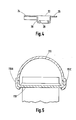
- a heat exchanger according to a first embodiment of the invention having a first header tank 11, a second heater tank 12, a heat exchanger core extending between the first and second header tanks 11, 12 and first and second casing members in the form of extruded top and bottom rails 15 and 16.
- the heat exchanger core includes a number of fluid transfer conduits in the form of oval tubes 13 each of which provides a fluid transfer connection between the first and second header tanks 11 and 12 and is separated from adjacent tubes 13 by an open structured heat transfer media in the form of a serpentine airway 14.
- Each of the serpentine airways 14 is made from a highly conductive material such as aluminium or one of its alloys and is jointed to the tubes 13 between which it is interposed to improve the transfer of heat from the respective tubes 13 into the air which, in use, flows through the serpentine airway 14.
- Each of the tubes 13 is coated before assembly with a brazing material used to secure it upon assembly.
- a turbulator 17 is fitted into each of the tubes 13 and is secured to the inner surface of each of the tubes 13.
- the turbulators 17 are provided to increase the strength of the tubes 13 and also to improve the transfer of heat from the fluid passing through the tube into the wall of the respective tube.
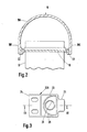
- Each of the header tanks 11, 12 includes a plate member in the form of a tube plate 18, a side wall member 19 in the form of a substantially U-shaped extrusion connected to said tube plate 18 to define a fluid manifold, each end of each fluid manifold being closed by a respective end cap 20A,B, 21A,B.
- Each side wall member 19 is a substantially U-shaped aluminium alloy extrusion and has a semi-circular portion 19A and two flat leg portions 19B, 19C joined together by said semi-circular portion 19A.
- Each of said leg portions 19B, 19C has an inwardly facing groove 22 in it near to its free end.
- Each of the tube plates 18 is a substantially flat pressed component having two longitudinal edges and has a number of apertures 10 in it into each of which is located and secured one end of one of the tubes 13.
- Each tube plate 18 is coated before assembly with a brazing material and flux to enable it to be secured upon assembly to the co-operating side wall 19.
- Each of the tube plates 18 is engaged upon assembly with the grooves 22 in the respective side wall member 19 with which it co-operates, before being secured in position by brazing.
- Each of the end caps 20A,B, 21A,B has a peripheral flange 23 and a tapered spigot 28 to locate it in the end of the fluid manifold with which it is engaged.
- Each of the end caps 20A,B, 21A,B is pressed from a sheet material which has been coated with a brazing material used during assembly to secure the respective end cap in position, and is extended at one position to provide a bracket means 24 and at another position to provide a location means in the form of a tongue 25.
- the bracket means 24 are used to connect, in use, the heat exchanger to some support structure such as part of a body of a motor vehicle.
- the end cap 20A is provided with inlet means 29 to connect the respective tank 11 of which it forms a part of a supply of oil to be cooled from an engine (not shown) and the end cap 20B is similarly provided with outlet means to connect the respective tank 12 of which it forms a part with the engine (not shown) which requires a supply of oil that has been cooled.
- Each of the rails 15, 16 has a re-entrant groove 26 extending along its length into which is engaged a respective one of the tongues 25 , the tongues 25 being secured during assembly by brazing.
- Each of the end caps 20A,B, 21A,B is engaged and secured both to one of the rails 15,16 and to one of the header tanks 11,12 therebeing engagement of the tongues 25 with the grooves 26 and engagement of the tapered spigots 28 with the manifolds.
- the end caps 20A,B, 21A,B therefore provide a rigid mechanical connection between the rails 15,16 and the header tanks 11,12.
- the re-entrant groove 26 in each of the rails 15, 16 is also used to connect at least one substantially T-shaped bracket 27 to each of the rails 15, 16 and hence to the heat exchanger.
- Each of the bracket 27 is engaged and slid along the groove 26 in which it is engaged to a desired position prior to the engagement and brazing of the end caps 20A,B, 21A,B and is secured in that position by brazing at the same time as the end caps are brazed to the rails 15,16.
- the oval tubes 13, the rails 15, 16, the side walls 19 and the brackets 27 are all produced by cutting from a length of extruded material of the desired cross-sectional shape a piece of suitable length.
- the width of the heat exchanger can therefore be easily altered by simply changing the length of the material cut to form the rails 15, 16 and the tubes 13.
- the height of the heat exchanger can also be altered by changing the length of the material cut to form the side walls 19 but in this case it is also necessary to produce longer tube plates 18 with more apertures 10 punched in them to accommodate the greater number of tubes 13.
- brackets 27 are first slid into the grooves 26 in the top and bottom rails 15 and 16 and then the end caps 20A, 20B and 21A, 21B are fitted to the top and bottom rails 15 and 16, the tongue 25 of each end cap 20A,20B,21A,21B being inserted into the groove 26, the top and bottom rails 15 and 16 are then staked to mechanically hold the tongues 25 in the grooves 26.
- each of the tubes 13 is fitted each with one of the turbulators 17 and then to complete the sub-assembly the tubes 13 and the serpentine airways 14 are alternately stacked on a slave clamp (not shown) until the correct number of tubes for the heat exchanger being built are present.
- the next stage is to fit the tube plates 18 and the side wall members 19 to the sub-assembled heat exchanger core. Firstly, the ends of the tubes 13 are engaged with the apertures 10 in the tube plates 18 and then the side wall members 19 are slid into engagment with the tube plates 18, the inwardly facing grooves 22 of the side wall members 29 being engaged with the longitudinal edges of the tube plates 18.
- bottom rail 16 complete with end caps 21A,21B is then placed upon a final assembly jig (not shown) and the bottom most serpentine airway 14 is placed on top of the bottom rail 16.
- the sub-assembled heat exchanger core complete with tube plates 18 and side walls 19 is then placed on top of the bottom airway 14 so that the spigots 28 of the end caps 21A, 21B, become engaged with the lower ends of the manifold s defined by the side wall members 19 and the tube plates 18.
- top rail 15 complete with end caps 20A,20B is then brought into position, the spigots 28 of the end caps 21A,21B being engaged with the upper ends of the manifolds defined by the side wall members 19 and the tube plates 18.
- top and bottom rails 15,16 are then urged towards each other by the clamping effect of the final assembly jig thereby forcing the end caps 20A,20B,21A,21B fully into engagement with the manifolds.
- the final assembly jig and completed but as yet not secured heat exchanger is then placed in a furnace where it is brought to a sufficiently high temperature to produce brazing of the pre-assembled parts.
- the heat exchanger is removed from the furnace and allowed to cool before being cleaned and pressure tested.
- the heat exchanger is substantially as hereinbefore described with the exception of the construction of the header tanks.
- end caps are push fitted into the end of the fluid manifolds it is envisaged that external end caps could alternatively be used to close the ends of the fluid manifolds and in this case the end caps would fit outside the tube plate and side wall.
Landscapes
- Engineering & Computer Science (AREA)
- Physics & Mathematics (AREA)
- Thermal Sciences (AREA)
- Mechanical Engineering (AREA)
- General Engineering & Computer Science (AREA)
- Heat-Exchange Devices With Radiators And Conduit Assemblies (AREA)
- Details Of Heat-Exchange And Heat-Transfer (AREA)
Applications Claiming Priority (2)
| Application Number | Priority Date | Filing Date | Title |
|---|---|---|---|
| GB8625142 | 1986-10-21 | ||
| GB8625142A GB2196730B (en) | 1986-10-21 | 1986-10-21 | A heat exchanger |
Publications (1)
| Publication Number | Publication Date |
|---|---|
| EP0266108A1 true EP0266108A1 (de) | 1988-05-04 |
Family
ID=10606051
Family Applications (1)
| Application Number | Title | Priority Date | Filing Date |
|---|---|---|---|
| EP87309203A Withdrawn EP0266108A1 (de) | 1986-10-21 | 1987-10-19 | Wärmeaustauscher |
Country Status (4)
| Country | Link |
|---|---|
| US (1) | US4938284A (de) |
| EP (1) | EP0266108A1 (de) |
| JP (1) | JPS63105400A (de) |
| GB (1) | GB2196730B (de) |
Cited By (6)
| Publication number | Priority date | Publication date | Assignee | Title |
|---|---|---|---|---|
| FR2664370A1 (fr) * | 1989-02-17 | 1992-01-10 | Diesel Kiki Co | Echangeur de chaleur du type a flux parallele monte sur vehicule. |
| EP0573095A3 (de) * | 1992-06-01 | 1994-02-23 | Gen Motors Corp | |
| EP0647824A1 (de) * | 1993-10-11 | 1995-04-12 | Valeo Thermique Moteur | Wärmetauscher, insbesondere als Ölkühler benutzt |
| DE4339952A1 (de) * | 1993-11-24 | 1995-06-01 | Behr Gmbh & Co | Wärmetauscher mit mehreren parallelen Flachrohren |
| WO1997012192A1 (de) * | 1995-09-26 | 1997-04-03 | Arup Alu-Rohr- U. Profil Gmbh | Wasserkasten für eine kühlereinrichtung sowie verfahren zu seiner herstellung |
| EP0795732A3 (de) * | 1996-03-16 | 1999-01-07 | Regent Heat Transfer Limited | Wärmeaustausch-Vorrichtung |
Families Citing this family (48)
| Publication number | Priority date | Publication date | Assignee | Title |
|---|---|---|---|---|
| JPH0522764Y2 (de) * | 1988-12-29 | 1993-06-11 | ||
| US5127466A (en) * | 1989-10-06 | 1992-07-07 | Sanden Corporation | Heat exchanger with header bracket and insertable header plate |
| JPH0639255Y2 (ja) * | 1989-12-07 | 1994-10-12 | 株式会社ゼクセル | 熱交換器のヘッダ構造 |
| US5107926A (en) * | 1990-04-03 | 1992-04-28 | Thermal Components, Inc. | Manifold assembly for a parallel flow heat exchanger |
| US5152339A (en) * | 1990-04-03 | 1992-10-06 | Thermal Components, Inc. | Manifold assembly for a parallel flow heat exchanger |
| JPH0470391U (de) * | 1990-10-30 | 1992-06-22 | ||
| JP2968063B2 (ja) * | 1991-02-20 | 1999-10-25 | サンデン株式会社 | 熱交換器 |
| US5062476A (en) * | 1991-02-28 | 1991-11-05 | General Motors Corporation | Heat exchanger with an extruded tank |
| US5228512A (en) * | 1991-04-02 | 1993-07-20 | Modine Manufacturing Company | Aluminum charge air cooler and method of making the same |
| JP2546505Y2 (ja) * | 1991-05-23 | 1997-09-03 | 株式会社ゼクセル | 熱交換器のブラケット取付構造 |
| US5125454A (en) * | 1991-08-27 | 1992-06-30 | Thermal Components, Inc. | Manifold assembly for a parallel flow heat exchanger |
| AU2490292A (en) * | 1991-08-27 | 1993-03-16 | Thermal Components, Inc. | Manifold assembly for a parallel flow heat exchanger |
| US5307870A (en) * | 1991-12-09 | 1994-05-03 | Nippondenso Co., Ltd. | Heat exchanger |
| US5289873A (en) * | 1992-06-22 | 1994-03-01 | General Motors Corporation | Heat exchanger sideplate interlocked with header |
| JPH0622018U (ja) * | 1992-08-27 | 1994-03-22 | サンデン株式会社 | 熱交換器のブラケット構造 |
| KR950009505B1 (ko) * | 1993-03-05 | 1995-08-23 | 주식회사두원공조 | 자동차의 에어콘용 열교환기의 제조방법 |
| US5697546A (en) * | 1993-04-30 | 1997-12-16 | Cicioni; Albert Brian | Method of forming a compact hydraulic radiator for use in construction equipment and fabrication thereof |
| US5366007A (en) * | 1993-08-05 | 1994-11-22 | Wynn's Climate Systems, Inc. | Two-piece header |
| JP2774237B2 (ja) * | 1993-10-06 | 1998-07-09 | 株式会社 マルナカ | 冷媒凝縮器用パイプ |
| US5346003A (en) * | 1993-10-12 | 1994-09-13 | General Motors Corporation | Face plumbed condenser for automotive air conditioner |
| JP3305460B2 (ja) * | 1993-11-24 | 2002-07-22 | 昭和電工株式会社 | 熱交換器 |
| US5450896A (en) * | 1994-01-25 | 1995-09-19 | Wynn's Climate Systems, Inc. | Two-piece header |
| US5538079A (en) * | 1994-02-16 | 1996-07-23 | Pawlick; Daniel R. | Heat exchanger with oblong grommetted tubes and locating plates |
| SE9401212L (sv) * | 1994-04-11 | 1995-04-03 | Valeo Engine Cooling Ab | Värmeväxlartank med ändstycken samt värmeväxlare försedd med densamma |
| FR2721099B1 (fr) * | 1994-06-08 | 1996-07-19 | Valeo Thermique Moteur Sa | Echangeur de chaleur utile notamment pour le refroidissement d'un flux d'air à haute température. |
| SE516092C2 (sv) * | 1995-01-25 | 2001-11-19 | Valeo Engine Cooling Ab | Värmeväxlartank för montering i en oljekylare, förfarande för framställning av en sådantank, samt värmeväxlare |
| SE9500249L (sv) * | 1995-01-25 | 1996-03-25 | Valeo Engine Cooling Ab | Värmeväxlartank med ändstycken, förfarande för framställning av en sådan tank, samt värmeväxlare försedd med en sådan |
| US5529117A (en) * | 1995-09-07 | 1996-06-25 | Modine Manufacturing Co. | Heat exchanger |
| JP2587058Y2 (ja) * | 1996-04-26 | 1998-12-14 | 株式会社ゼクセル | 熱交換器のヘッダ構造 |
| JP2587057Y2 (ja) * | 1996-04-26 | 1998-12-14 | 株式会社ゼクセル | 熱交換器のヘッダ構造 |
| JP3026754B2 (ja) * | 1996-05-02 | 2000-03-27 | 株式会社ゼクセル | パラレルフロータイプ熱交換器のヘッダパイプの製造方法 |
| FR2749649B1 (fr) * | 1996-06-05 | 1998-09-04 | Valeo Thermique Moteur Sa | Radiateur de vehicule brase muni d'un support d'accessoire |
| JP3912836B2 (ja) * | 1997-02-21 | 2007-05-09 | サンデン株式会社 | 熱交換器 |
| GB2356923A (en) * | 1999-11-30 | 2001-06-06 | Delphi Tech Inc | Heat exchanger |
| JP2002081884A (ja) * | 2000-09-07 | 2002-03-22 | Denso Corp | 熱交換器の取付構造 |
| DE10237769A1 (de) * | 2002-08-17 | 2004-02-26 | Modine Manufacturing Co., Racine | Wärmeaustauscher und Verfahren zur Herstellung |
| DE10256869A1 (de) * | 2002-12-04 | 2004-06-24 | Behr Gmbh & Co. Kg | Wärmeübertrager |
| CA2433697A1 (en) * | 2003-06-27 | 2004-12-27 | Dana Canada Corporation | Vibration-resistant mounting bracket for heat exchangers |
| US7051789B2 (en) * | 2004-04-22 | 2006-05-30 | Dana Canada Corporation | Two-piece mounting bracket for heat exchanger |
| CN100433392C (zh) * | 2006-12-01 | 2008-11-12 | 王双玲 | 半导体致冷设备专用翼管形散热器及其制备方法 |
| JP5746906B2 (ja) * | 2011-04-28 | 2015-07-08 | 昭和電工株式会社 | 熱交換器 |
| DE102011077838A1 (de) * | 2011-06-20 | 2012-12-20 | Behr Gmbh & Co. Kg | Wärmetauscher und Verfahren zur Herstellung eines Wärmetauschers |
| DE112015002163T5 (de) * | 2014-05-08 | 2017-02-09 | Dana Canada Corporation | Wärmetauscher mit aufschiebbarer Befestigungshalterung |
| DE102014219387A1 (de) * | 2014-09-25 | 2016-03-31 | Mahle International Gmbh | Sammler und zugehöriger Wärmeübertrager |
| JP6583071B2 (ja) * | 2015-03-20 | 2019-10-02 | 株式会社デンソー | タンク、および熱交換器 |
| US10563930B2 (en) | 2016-01-12 | 2020-02-18 | Hussmann Corporation | Heat exchanger including coil end close-off cover |
| CN105545445B (zh) * | 2016-02-23 | 2021-06-25 | 浙江银轮机械股份有限公司 | 一种冷却系统 |
| CN121206959A (zh) * | 2024-06-26 | 2025-12-26 | 丹佛斯有限公司 | 集流管、换热装置和集流管制造方法 |
Citations (7)
| Publication number | Priority date | Publication date | Assignee | Title |
|---|---|---|---|---|
| GB860359A (en) * | 1958-09-16 | 1961-02-01 | Morris Motors Ltd | Improvements relating to brazed light alloy heat-exchangers |
| US3113615A (en) * | 1961-05-08 | 1963-12-10 | Modine Mfg Co | Heat exchanger header construction |
| US3246691A (en) * | 1963-11-27 | 1966-04-19 | Fedders Corp | Radiators |
| US3265126A (en) * | 1963-11-14 | 1966-08-09 | Borg Warner | Heat exchanger |
| FR2214874A1 (de) * | 1973-01-20 | 1974-08-19 | Sueddeutsche Kuehler Behr | |
| CH612748A5 (en) * | 1975-01-20 | 1979-08-15 | Alfer Alu Fertigbau | Hot water radiator |
| GB2098313A (en) * | 1981-05-09 | 1982-11-17 | Imi Radiators | Heat exchanger for automobiles |
Family Cites Families (5)
| Publication number | Priority date | Publication date | Assignee | Title |
|---|---|---|---|---|
| US2899177A (en) * | 1959-08-11 | Method of making same | ||
| GB840451A (en) * | 1957-09-21 | 1960-07-06 | Morris Motors Ltd | Improvements relating to brazed light alloy heat-exchangers |
| US3415315A (en) * | 1966-06-29 | 1968-12-10 | Borg Warner | Heat exchanger |
| US3866675A (en) * | 1973-08-03 | 1975-02-18 | Modine Mfg Co | Method of making a heat exchanger and a heat exchanger |
| FR2243037B1 (de) * | 1973-09-06 | 1977-08-05 | Chausson Usines Sa |
-
1986
- 1986-10-21 GB GB8625142A patent/GB2196730B/en not_active Expired
-
1987
- 1987-09-23 US US07/100,270 patent/US4938284A/en not_active Expired - Fee Related
- 1987-10-19 EP EP87309203A patent/EP0266108A1/de not_active Withdrawn
- 1987-10-20 JP JP62262956A patent/JPS63105400A/ja active Pending
Patent Citations (7)
| Publication number | Priority date | Publication date | Assignee | Title |
|---|---|---|---|---|
| GB860359A (en) * | 1958-09-16 | 1961-02-01 | Morris Motors Ltd | Improvements relating to brazed light alloy heat-exchangers |
| US3113615A (en) * | 1961-05-08 | 1963-12-10 | Modine Mfg Co | Heat exchanger header construction |
| US3265126A (en) * | 1963-11-14 | 1966-08-09 | Borg Warner | Heat exchanger |
| US3246691A (en) * | 1963-11-27 | 1966-04-19 | Fedders Corp | Radiators |
| FR2214874A1 (de) * | 1973-01-20 | 1974-08-19 | Sueddeutsche Kuehler Behr | |
| CH612748A5 (en) * | 1975-01-20 | 1979-08-15 | Alfer Alu Fertigbau | Hot water radiator |
| GB2098313A (en) * | 1981-05-09 | 1982-11-17 | Imi Radiators | Heat exchanger for automobiles |
Cited By (9)
| Publication number | Priority date | Publication date | Assignee | Title |
|---|---|---|---|---|
| FR2664370A1 (fr) * | 1989-02-17 | 1992-01-10 | Diesel Kiki Co | Echangeur de chaleur du type a flux parallele monte sur vehicule. |
| EP0573095A3 (de) * | 1992-06-01 | 1994-02-23 | Gen Motors Corp | |
| EP0647824A1 (de) * | 1993-10-11 | 1995-04-12 | Valeo Thermique Moteur | Wärmetauscher, insbesondere als Ölkühler benutzt |
| FR2711235A1 (fr) * | 1993-10-11 | 1995-04-21 | Valeo Thermique Moteur Sa | Echangeur de chaleur utile notamment comme radiateur d'huile. |
| DE4339952A1 (de) * | 1993-11-24 | 1995-06-01 | Behr Gmbh & Co | Wärmetauscher mit mehreren parallelen Flachrohren |
| DE4339952B4 (de) * | 1993-11-24 | 2005-10-27 | Behr Gmbh & Co. Kg | Wärmetauscher mit mehreren parallelen Flachrohren |
| WO1997012192A1 (de) * | 1995-09-26 | 1997-04-03 | Arup Alu-Rohr- U. Profil Gmbh | Wasserkasten für eine kühlereinrichtung sowie verfahren zu seiner herstellung |
| GB2322933A (en) * | 1995-09-26 | 1998-09-09 | Arup Alu Rohr U Profil Gmbh | Water tank for a radiator systen and method for the production thereof |
| EP0795732A3 (de) * | 1996-03-16 | 1999-01-07 | Regent Heat Transfer Limited | Wärmeaustausch-Vorrichtung |
Also Published As
| Publication number | Publication date |
|---|---|
| GB8625142D0 (en) | 1986-11-26 |
| GB2196730A (en) | 1988-05-05 |
| GB2196730B (en) | 1991-06-26 |
| JPS63105400A (ja) | 1988-05-10 |
| US4938284A (en) | 1990-07-03 |
Similar Documents
| Publication | Publication Date | Title |
|---|---|---|
| EP0266108A1 (de) | Wärmeaustauscher | |
| CA2142233C (en) | Heat exchanger with oblong grommetted tubes and locating plates | |
| US4501321A (en) | After cooler, charge air cooler and turbulator assemblies and methods of making the same | |
| US8002022B2 (en) | Heat exchanger, in particular exhaust gas heat exchanger for motor vehicles | |
| US6311768B1 (en) | Clip on manifold heat exchanger | |
| JP3043025B2 (ja) | 熱交換器 | |
| EP2171246B1 (de) | Herstellungsverfahren für wärmetauscher | |
| EP1459029B1 (de) | Befestigungselement für wärmetauscher | |
| US5791402A (en) | Brazed radiator for a vehicle having an accessory support | |
| EP0102715A2 (de) | Wärmetauscher | |
| GB2089692A (en) | Manufacturing heat exchangers | |
| CA2433975C (en) | Ribbed mounting bracket for heat exchangers | |
| US20080230213A1 (en) | Fully-Metal Heat Exchanger And Method For Its Production | |
| EP0760457B1 (de) | Wärmetauscher | |
| AU2004252192A1 (en) | Vibration-resistant mounting bracket for heat exchangers | |
| EP0384612A2 (de) | Ölkühler in einem Tank | |
| JPH03225197A (ja) | 熱交換器 | |
| JP2989855B2 (ja) | 複式熱交換器 | |
| JPH11192833A (ja) | 熱交換器組み合わせ構造及び一体型熱交換器 | |
| JPH0571892A (ja) | 熱交換器 | |
| JPH04288486A (ja) | 熱交換器における取付け用ブラケットのろう付け方法 | |
| JPH04288487A (ja) | 熱交換器における取付け用ブラケットのろう付け方法 | |
| GB2254687A (en) | Heat exchanger | |
| JPH04288484A (ja) | 熱交換器における取付け用ブラケットの一括ろう付け方法 | |
| US6742256B2 (en) | Method and apparatus for flexible construction of heat exchanger tanks |
Legal Events
| Date | Code | Title | Description |
|---|---|---|---|
| PUAI | Public reference made under article 153(3) epc to a published international application that has entered the european phase |
Free format text: ORIGINAL CODE: 0009012 |
|
| AK | Designated contracting states |
Kind code of ref document: A1 Designated state(s): DE ES FR GB IT SE |
|
| 17P | Request for examination filed |
Effective date: 19881025 |
|
| 17Q | First examination report despatched |
Effective date: 19890710 |
|
| STAA | Information on the status of an ep patent application or granted ep patent |
Free format text: STATUS: THE APPLICATION IS DEEMED TO BE WITHDRAWN |
|
| 18D | Application deemed to be withdrawn |
Effective date: 19911105 |