EP0266130A2 - Mehrflächen-Schleifmaschine - Google Patents
Mehrflächen-Schleifmaschine Download PDFInfo
- Publication number
- EP0266130A2 EP0266130A2 EP87309346A EP87309346A EP0266130A2 EP 0266130 A2 EP0266130 A2 EP 0266130A2 EP 87309346 A EP87309346 A EP 87309346A EP 87309346 A EP87309346 A EP 87309346A EP 0266130 A2 EP0266130 A2 EP 0266130A2
- Authority
- EP
- European Patent Office
- Prior art keywords
- grinding
- grinding wheel
- workpiece
- wheel
- plane
- Prior art date
- Legal status (The legal status is an assumption and is not a legal conclusion. Google has not performed a legal analysis and makes no representation as to the accuracy of the status listed.)
- Withdrawn
Links
Images

Classifications
-
- B—PERFORMING OPERATIONS; TRANSPORTING
- B24—GRINDING; POLISHING
- B24B—MACHINES, DEVICES, OR PROCESSES FOR GRINDING OR POLISHING; DRESSING OR CONDITIONING OF ABRADING SURFACES; FEEDING OF GRINDING, POLISHING, OR LAPPING AGENTS
- B24B7/00—Machines or devices designed for grinding plane surfaces on work, including polishing plane glass surfaces; Accessories therefor
- B24B7/10—Single-purpose machines or devices
- B24B7/16—Single-purpose machines or devices for grinding end-faces, e.g. of gauges, rollers, nuts, piston rings
Definitions
- ground E-cores have been provided with the two outer arms and the central arm being all of substantially the same length.
- the centre leg of E-cores In some products, there is a need for the centre leg of E-cores to be shorter than the two outer legs to provide an air gap between two mated coils. Difficulties exist in the production of such a design of E-core, where the middle arm is generally 0.002 to 0.04 inch (0.05 to 1.0 mm) shorter than the outer arms. Generally a separate grinding step for the middle arm is required, which results in a significant increase in the cost of manufacturing E-cores of that design.
- the present invention discloses a grinding apparatus, modified to grind items, and specifically E-cores, in more than one plane, so that first and second ground areas on the product may be in different planes.
- the grinding procedure may be performed in a single operation, without need to mount the items to be ground into two different machines in two different productions.
- a considerable saving in manufacturing costs can be achieved, while at the same time improved accuracy of grinding can be obtained since the two planes of grinding may be well correlated with each other.
- any desired workpiece may be ground in the apparatus of this invention, for single step grinding in two or more planes.
- grinding apparatus which comprises a first grinding wheel, said means for presenting a workpiece for grinding to said first grinding wheel, a second grinding wheel carried with the first grinding wheel and positioned so that the presenting means can also present a portion of the workpiece to said second grinding wheel for grinding.
- the first wheel i.e., its grinding surface
- the first wheel is rotatable in a first plane
- the grinding surface of the second wheel is rotatable in a plane different from the first plane.
- the portion of the workpiece ground by the second wheel is ground to a different plane from other workpiece portions which are ground by the first grinding wheel.
- the first and second grinding wheels are in coaxial relation with each other.
- a standard Through-Feed grinder manufactured by the Swiss company Famtec, may be used as a basic grinding apparatus, to be modified in accordance with this invention by providing the second grinding wheel, typically inside of the first grinding wheel, about the centre of rotation of the first grinding wheel.
- the means for presenting the workpiece for grinding may constitute guide track means for carrying the workpiece across said first and second grinding wheels in a diametric or chordal path.
- the track means may be proportioned for moving E-cores first across the first grinding wheel in a position to grind at least the ends of the outer arms of the E-cores, followed by moving the E-cores across the second grinding wheel in a position to grind only the end of the central arm.
- the central arm will be ground by the first grinding wheel also.
- only the central arm is ground by the second grinding wheel, which has its grinding surface positioned approximately 0.002 to 0.04 inch (0.05 to 1.0 mm) above the grinding surface of the first grinding wheel.
- the second grinding wheel is of less diameter at its grinding surface than the distance between each pair of outer arms of the E-core, so that the outer arms do not engage the second grinding wheel.
- the first grinding wheel, and also the second grinding wheel, if desired, may define an inner rim that is higher than its outer rim.
- parts travelling on a chordal or diametric path across the grinding wheel may have their final sizing controlled by the position of the inner rim, while rougher grinding takes place on the outer portions of the grinding wheels.
- the invention may be used with any other desired type of grinder as well, e.g. vertical spindle grinders with either a rotary or a reciprocating table, with parts travelling on a curved path across the grinding wheels.
- vertical spindle grinders with either a rotary or a reciprocating table, with parts travelling on a curved path across the grinding wheels.
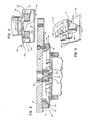
- grinding apparatus 10 is disclosed, of conventional design, except as otherwise shown herein.
- Frame 12 carries a first grinding wheel 14, bolted to backing plate 16, and of generally conventional design.
- grinding wheel 14 may be a standard 10 inch (25.4 cm) diamond grinding wheel, with the grinding surface 18 being a diamond abrasive surface, and shown as in Figure 2 to have an inner rim 20 that is higher than its outer rim 22.
- the term "higher” in this special context still applies even through grinding wheel 14, carried on annular support 15, is inverted. In other words, the term “higher” is essentially synonymous with -- outwardly projecting --, relative to the workpiece.
- a two bar guide track 24 is disclosed, along which E-core workpiece 32 may pass, with each bar of guide track 24 resting between the respective outer arms 28 and central arm 30 of E-core 32.
- other designs of guide systems may also be used.
- a second grinding wheel 34 is provided, being carried by a support member 36, which is bolted to backing plate 16 as shown in Figure 2.
- Support member 36 may be shimmed by shims 38 to cause second grinding wheel 34 to occupy a plane different from the plane occupied by grinding surface 18 of first grinding ring 14. Otherwise, adjusting screws or the like may be used. Specifically, this can be shown by the difference between edge line 40 which defines the level of the inner edge 20 of first grinding ring 14, and edge line 42, which defines the level of the inner portion of second grinding ring 34.
- the gap typically 0.002 to 0.04 inch (0.05 to 1.0 mm) but actually any desired gap, can be given by comparison of lines 40, 42.
- second grinding ring 34 may be tapered so that its inner portion stands out farther than its outer portions. If desired, the outer portions of second ring 34 may have a level that overlaps the plane of first grinding ring 14, although it would be usual to adjust the system so that no overlapping of levels is provided.
- E-cores 32 are moved along guide track 24, carried by high friction belt 46 positioned underneath guide track 24.
- Friction belt 46 advances the E-core, with their respective arms pointing upwardly, while the individual tracks of guide track 24 are optionally present to keep the E-core in position as it is moved along high friction belt 46.
- Belt 46 brings E-cores 32 one by one into contact with first grinding wheel 14, at which point at least the outer arms 28 of E-cores 32 are ground to the desired length and texture, depending particularly upon the positioning of inner portion 20 of the first grinding ring. Following this, high friction belt 46 causes the E-cores 32 to be advanced along rails 24 to bring central arm 30 across grinding wheel 34, in typically a diametric path as shown for both the first and second grinding wheels. Since second grinding wheel 34 is too small to engage outer arms 28 of the E-core, and since second grinding wheel 34 is in an advanced plane different from the plane of first grinding wheel 18, central arm 30 of each E-core 32 is ground slightly shorter than the outer arms 28, as shown in possible exaggerated proportions in figure 3. Following this, E-core 32 may continue along belt 46 to be picked off or dropped in any conventional manner for shipping or further processing.
- E-cores or any other desired workpiece may be ground in two or more separate planes in a single manufacturing step, for a significant increase in manufacturing efficiency, and a reduction in cost.
- the accuracy in grinding can be increased, because the two (or more if desired) grinding wheels are carried together on a single apparatus, and thus may be precisely positioned relative to each other, with less possibility of getting out of adjustment.
Landscapes
- Engineering & Computer Science (AREA)
- Mechanical Engineering (AREA)
- Grinding Of Cylindrical And Plane Surfaces (AREA)
- Finish Polishing, Edge Sharpening, And Grinding By Specific Grinding Devices (AREA)
Applications Claiming Priority (2)
| Application Number | Priority Date | Filing Date | Title |
|---|---|---|---|
| US923669 | 1986-10-27 | ||
| US06/923,669 US5134807A (en) | 1986-10-27 | 1986-10-27 | Multilevel grinding apparatus |
Publications (2)
| Publication Number | Publication Date |
|---|---|
| EP0266130A2 true EP0266130A2 (de) | 1988-05-04 |
| EP0266130A3 EP0266130A3 (de) | 1990-03-07 |
Family
ID=25449069
Family Applications (1)
| Application Number | Title | Priority Date | Filing Date |
|---|---|---|---|
| EP87309346A Withdrawn EP0266130A3 (de) | 1986-10-27 | 1987-10-22 | Mehrflächen-Schleifmaschine |
Country Status (2)
| Country | Link |
|---|---|
| US (1) | US5134807A (de) |
| EP (1) | EP0266130A3 (de) |
Families Citing this family (12)
| Publication number | Priority date | Publication date | Assignee | Title |
|---|---|---|---|---|
| JPH11300607A (ja) * | 1998-04-16 | 1999-11-02 | Speedfam-Ipec Co Ltd | 研磨装置 |
| CN105397590B (zh) * | 2015-12-29 | 2017-05-31 | 中信戴卡股份有限公司 | 一种尺寸可调的车轮在线去毛刺装置 |
| CN106826455B (zh) * | 2017-03-20 | 2018-08-07 | 中信戴卡股份有限公司 | 一种多功能车轮去毛刺装置 |
| CN107363669A (zh) * | 2017-06-20 | 2017-11-21 | 中信戴卡股份有限公司 | 一种车轮正面毛刺清理装置 |
| CN107336022A (zh) * | 2017-07-21 | 2017-11-10 | 中信戴卡股份有限公司 | 一种车轮毛坯定位轮唇矫正装置 |
| CN107297655A (zh) * | 2017-07-21 | 2017-10-27 | 中信戴卡股份有限公司 | 一种车轮法兰刷毛刺装置 |
| CN107414097B (zh) * | 2017-08-27 | 2024-01-23 | 中信戴卡股份有限公司 | 一种车轮外轮缘圆角修整装置 |
| CN107350944B (zh) * | 2017-08-30 | 2023-08-15 | 中信戴卡股份有限公司 | 一种车轮边角打磨装置 |
| CN108115499B (zh) * | 2017-12-25 | 2023-08-22 | 中信戴卡股份有限公司 | 一种车轮随形刷毛刺装置 |
| CN108031929B (zh) * | 2017-12-29 | 2023-11-17 | 中信戴卡股份有限公司 | 一种去除车轮帽口接刀棱毛刺的装置 |
| CN108057931A (zh) * | 2017-12-29 | 2018-05-22 | 中信戴卡股份有限公司 | 一种去除车轮接刀棱毛刺装置 |
| CN109158978A (zh) * | 2018-11-06 | 2019-01-08 | 中信戴卡股份有限公司 | 一种车轮减重窝清理装置 |
Family Cites Families (3)
| Publication number | Priority date | Publication date | Assignee | Title |
|---|---|---|---|---|
| GB1339266A (en) * | 1970-08-28 | 1973-11-28 | Williams D G | Grinding or the like machine |
| SU672005A1 (ru) * | 1976-08-13 | 1979-07-05 | Ордена Трудового Красного Знамени Институт Сверхтвердых Материалов Ан Украинской Сср | Шлифовальный инструмент |
| DE2739135A1 (de) * | 1977-08-31 | 1979-03-15 | Bbc Brown Boveri & Cie | Verfahren zur bearbeitung der schenkelenden eines werkstueckes mit wenigstens drei schenkeln |
-
1986
- 1986-10-27 US US06/923,669 patent/US5134807A/en not_active Expired - Fee Related
-
1987
- 1987-10-22 EP EP87309346A patent/EP0266130A3/de not_active Withdrawn
Also Published As
| Publication number | Publication date |
|---|---|
| US5134807A (en) | 1992-08-04 |
| EP0266130A3 (de) | 1990-03-07 |
Similar Documents
| Publication | Publication Date | Title |
|---|---|---|
| EP0266130A2 (de) | Mehrflächen-Schleifmaschine | |
| US5997390A (en) | Polishing apparatus with improved alignment of polishing plates | |
| US20020081954A1 (en) | Grinding machine | |
| CN113442014B (zh) | 一种附带侧导向挡料机构的全自动智能卷板机 | |
| JPH01220633A (ja) | 互いに前後して運動する物体間の距離を変化させる装置 | |
| KR20040030974A (ko) | 크랭크샤프트의 중심 베어링 연삭방법과 장치 | |
| MY141458A (en) | Method and apparatus for grinding a workpieces | |
| EP0765712A1 (de) | Vorrichtung zum Abrichten von Schleifscheiben | |
| KR100380558B1 (ko) | 훼라이트코어의 간극연마장치 | |
| US4821459A (en) | Multilevel grinding apparatus and method | |
| JP2670787B2 (ja) | 多面研削装置 | |
| JPH1148107A (ja) | 両面研削方法およびその装置 | |
| US4437268A (en) | Beveling apparatus | |
| US5097631A (en) | Circular edger attachment for vertical glass edger | |
| CN117161960A (zh) | 一种轴承圈端面研磨设备 | |
| US4651471A (en) | Edge-rounding method and apparatus therefor | |
| JP3010462B2 (ja) | 自動研磨装置 | |
| KR970002083Y1 (ko) | 트랜스용 훼라이트코어의 중심축부에 형성되는 간극연마장치 | |
| EP0228157A2 (de) | Verfahren und Vorrichtung zum Anritzen kornorientierter Siliciumstahlbänder | |
| JP2000084846A (ja) | ウェーハ面取り装置 | |
| SU872222A2 (ru) | Приспособление дл магнитно-абразивной обработки деталей | |
| US3548545A (en) | Center-hole grinder | |
| SU1683956A1 (ru) | Станок дл обработки ферритовых деталей | |
| JPH0343143A (ja) | 両頭平面研削装置 | |
| JPH02131853A (ja) | 研削治具 |
Legal Events
| Date | Code | Title | Description |
|---|---|---|---|
| PUAI | Public reference made under article 153(3) epc to a published international application that has entered the european phase |
Free format text: ORIGINAL CODE: 0009012 |
|
| 17P | Request for examination filed |
Effective date: 19871111 |
|
| AK | Designated contracting states |
Kind code of ref document: A2 Designated state(s): CH DE FR GB IT LI SE |
|
| PUAL | Search report despatched |
Free format text: ORIGINAL CODE: 0009013 |
|
| AK | Designated contracting states |
Kind code of ref document: A3 Designated state(s): CH DE FR GB IT LI SE |
|
| 17Q | First examination report despatched |
Effective date: 19910712 |
|
| STAA | Information on the status of an ep patent application or granted ep patent |
Free format text: STATUS: THE APPLICATION IS DEEMED TO BE WITHDRAWN |
|
| 18D | Application deemed to be withdrawn |
Effective date: 19911123 |
|
| RIN1 | Information on inventor provided before grant (corrected) |
Inventor name: KEEFE, JAMES V. |