EP0266191A2 - Ausrichteverfahren für Plotter - Google Patents
Ausrichteverfahren für Plotter Download PDFInfo
- Publication number
- EP0266191A2 EP0266191A2 EP87309529A EP87309529A EP0266191A2 EP 0266191 A2 EP0266191 A2 EP 0266191A2 EP 87309529 A EP87309529 A EP 87309529A EP 87309529 A EP87309529 A EP 87309529A EP 0266191 A2 EP0266191 A2 EP 0266191A2
- Authority
- EP
- European Patent Office
- Prior art keywords
- sheet
- point
- transport
- axis
- chart
- Prior art date
- Legal status (The legal status is an assumption and is not a legal conclusion. Google has not performed a legal analysis and makes no representation as to the accuracy of the status listed.)
- Withdrawn
Links
- 238000000034 method Methods 0.000 title claims description 15
- 238000005520 cutting process Methods 0.000 claims abstract description 31
- 230000009977 dual effect Effects 0.000 claims abstract description 13
- 230000032258 transport Effects 0.000 claims description 76
- 230000033001 locomotion Effects 0.000 claims description 36
- 238000003860 storage Methods 0.000 claims description 14
- 239000003550 marker Substances 0.000 claims description 13
- 230000006872 improvement Effects 0.000 claims description 7
- 230000007246 mechanism Effects 0.000 abstract description 47
- 230000000694 effects Effects 0.000 description 4
- 230000003100 immobilizing effect Effects 0.000 description 4
- 238000004519 manufacturing process Methods 0.000 description 3
- 230000009471 action Effects 0.000 description 2
- 230000000712 assembly Effects 0.000 description 2
- 238000000429 assembly Methods 0.000 description 2
- 238000010276 construction Methods 0.000 description 2
- 239000012526 feed medium Substances 0.000 description 2
- 230000013011 mating Effects 0.000 description 2
- 230000004048 modification Effects 0.000 description 2
- 238000012986 modification Methods 0.000 description 2
- 238000005299 abrasion Methods 0.000 description 1
- 230000002730 additional effect Effects 0.000 description 1
- 230000002860 competitive effect Effects 0.000 description 1
- 239000000463 material Substances 0.000 description 1
- 239000002609 medium Substances 0.000 description 1
- 230000000630 rising effect Effects 0.000 description 1
- 238000000926 separation method Methods 0.000 description 1
- 230000001360 synchronised effect Effects 0.000 description 1
Images



Classifications
-
- G—PHYSICS
- G01—MEASURING; TESTING
- G01D—MEASURING NOT SPECIALLY ADAPTED FOR A SPECIFIC VARIABLE; ARRANGEMENTS FOR MEASURING TWO OR MORE VARIABLES NOT COVERED IN A SINGLE OTHER SUBCLASS; TARIFF METERING APPARATUS; MEASURING OR TESTING NOT OTHERWISE PROVIDED FOR
- G01D15/00—Component parts of recorders for measuring arrangements not specially adapted for a specific variable
- G01D15/28—Holding means for recording surfaces; Guiding means for recording surfaces; Exchanging means for recording surfaces
Definitions
- the present invention relates to plotters generally and, more particularly, to a plotter having features enabling unattended operation thereof and to a method for automatically aligning a chart with the plotter X-axis.
- Plotters convert digital information into graphic representation by using a chart and pen to produce line drawings from a series of individual points.
- the Cartesian coordinate system used to determine the position of these points consists of three orthogonal or mutually perpendicular axes known as X, Y and Z, the relationship of these axes to a typical plotter being shown in FIG. 2.
- These digital points are typically transmitted by a host computer, where they are created and stored.
- both the pen and chart are moved to produce a drawing.
- movement in the X-axis is accomplished by moving the chart in and out of the plotter, conventionally with a single drive drum and motor assembly.
- Y-axis movement is accomplished by moving the pen back and forth across the chart, conventionally with a drive belt and motor assembly.
- Z-axis movement is simply accomplished by moving the pen up off the chart or down onto the chart, conventionally by means of a solenoid. With these basic movements, the plotter is capable of producing virtually any kind of line drawing on the chart.
- a truly automatic plotter that is, a plotter having a reliable capability of unattended operation -- requires no elucidation.
- a truly automatic plotter would be able to accommodate either cut sheet or roll chart format, accommodate chart widths of a variety of standard drafting sizes, and be inexpensive to manufacture.
- the creation of such an automatic chart plotter requires the confluence of a number of different innovative features.
- the conventional X-axis drive uses a single motor to drive a large rod or drum with sprockets or friction drive surfaces to move the chart along the X-axis.
- an automatic plotter requires means for automatically aligning the chart with the plotter axes, especially the X-axis, during loading procedures and optionally at subsequent times.
- the automatic chart alignment means used during the loading procedure cooperates with the improved X-axis motor drive so that the chart is properly positioned in alignment with the plotter axes during the loading procedure and not accidentally caused to skew therefrom subsequently by the X-axis motor drive.
- the automatic plotter in order to enable the automatic plotter to utilize chart stock supplied in roll form and to cut this stock to a desired length for a given plot, the automatic plotter must have a chart cutting mechanism. In order to keep the cost of the automatic plotter competitive with conventional plotters, this feature should be implemented utilizing as much as possible of the existing plotter equipment.
- an automatic plotter must include a cut chart handling mechanism for handling (that is, retrieving and neatly and orderly storing) cut charts of varying length, as produced by the chart cutting mechanism.
- Another object is to provide such a plotter having an X-axis drive offering a low inertial load relative to the conventional X-axis drive.
- a further object is to provide a plotter having an automatic chart alignment feature so that it can accurately align a chart with the plotter X-axis.
- the plotter apparatus is adapted to receive a signal and comprises generally a frame, means for transporting a sheet through the frame along a first axis, and means for marking the sheet moving through the frame in accordance with the signal received.
- the improved X-axis drive mechanism utilizes as transporting means a pair of friction drives adapted to be disposed adjacent a first surface of the sheet adjacent respective opposed sides thereof.
- Each of a pair of means for driving the friction drives under independent control is adapted to drive its respective friction drive at an independent rate.
- the friction drives have aligned axes of rotation substantially transverse to the axis of transport of the sheet.
- Each of the friction drives is driven at a remote end by an associated one of the friction drives, there also being means secured to the frame for freely rotatably supporting the proximate ends of the friction drives (preferably, a single common support means for both proximate ends).
- the drive means are independently controlled to compensate for variations in the effective diameters of the friction drives, so that the pair of drive means are adapted to drive the friction drives under independent control so as to control skewing of the sheet by the friction drives. More particularly, the pair of drive means is adapted to cause controlled skewing and unskewing of the sheet.
- Bearing means adapted to be disposed adjacent a second surface of the sheet opposite said first surface and adjacent respective opposed sides thereof, engage the sheet and force the sheet into engagement with the pair of friction drives.
- the bearing means preferably comprises a substantially spaced pair of bearing members.
- the automatic chart alignment mechanism comprises a system for aligning a sheet being transported through the frame with a first linear side of the sheet parallel to the first axis of the frame.
- the mechanism utilizes as the transporting means a horizontally spaced pair of sheet transport means adapted to be disposed adjacent opposite sides of the sheet for independently transporting the sheet sides both forwardly and rearwardly.
- the transporting means operates in two basic modes: in the first mode, both transport means transport the sheet sides in the same direction at the same rate to transport the sheet forwardly or rearwardly; in the second mode, a first one of the transport means transports the first side of the sheet at a differential rate than a second one of the transport means transports the second side of the sheet (either forwardly or rearwardly) to swivel the sheet. Further provided are means spaced a given distance from the first transport means for sensing the first side of the sheet, and means for aligning the first side of the sheet with the sensing means.
- This aligning means comprises in turn means for swiveling a first point on the first side of the sheet across the sensing means to locate the first side and align it substantially at the first point with the sensing means, means for advancing the sheet the given distance, and means for swiveling a second point on the first side of the sheet across the sensing means to locate the first side and align it substantially at the second point with the sensing means, the first and second point being spaced apart the given distance.
- the first transport means is spaced the given distance from the first point when the first point is swiveled.
- the first transport means either retains a point on the first side stationary while the second transport means transports the second side to swivel the sheet about the point or transports it at a non-zero rate less than the second transport means transports the second side of the sheet to swivel the sheet.
- the swiveling means preferably swivels the first point back and forth across the sensing means.
- the sensing means is spaced a first given distance X1 from the first transport means, and the means for advancing the sheet from the first point A to the second point B advances the sheet the first given distance X1.
- the aligning means further comprises means for aligning by use of the sensing means two points A and B narrowly spaced from each other by the distance X1 along the first side of the sheet, means for then aligning by use of the sensing means a fourth point D widely spaced from point B by the distance X2 along the first side of the sheet, and means for finally aligning by computation and without use of the sensing means a third point C intermediate points B and D and narrowly spaced from point D by the distance X1 along the first side the sheet.
- a preferred embodiment of the means for aligning the first side of the sheet with the sensing means comprises means for advancing the sheet (after its substantial alignment at the second point B with the sensing means) a second given distance X2 substantially greater than the first given distance X1, and means for then swiveling a fourth point D on the first side of the sheet back and forth across the sensing means to locate the first side and align it substantially at the fourth point D with the sensing means by a net movement R of the second transport means.
- first and second, second and third, and third and fourth points A and B, B and C, and C and D are spaced apart in the same direction the distance X1, X2-X1 and X1, respectively.
- the first and second points A and B are preferably on opposite ends of a sheet (or contemplated plot) from the third and fourth points C and D.
- the first and third points A and C are held stationary by the first transport means as the second transport means swivels the second and fourth points B and D, respectively, across the sensing means, and the fourth point D is held stationary by the first transport means as the second transport means swivels the third point C towards the sensing means.
- the first transport means transports the first, third and fourth points A, C and D at a non-zero rate less than the second transport means transports the second side of the sheet to swivel the sheet.
- the sheet transport means comprises a rotatable friction drive and the movements R and R ⁇ are rotational movements. It will be appreciated that whereas the alignment with the sensing means of points A, B and D are based on physical determinations by the sensing means, the alignment of point C with the sensing means is determined mathematically.
- the chart cutting feature is found in plotter apparatus wherein the marking means comprises a marker holder for holding a marker (such as a pen), storage means (such as a carousel) for holding a plurality of markers, means for causing the holder to receive a selected marker from and to return it to the storage means, and means for moving the holder and any marker held thereby along a second axis of the sheet substantially perpendicular to the first axis and along a third axis substantially perpendicular to the sheet.
- the chart cutting mechanism comprises a knife means for cutting the sheet along the second axis, the knife means being configured and dimensioned to be received, held and returned by the holder and held by the storage means as a marker.
- the moving means comprises means for first moving the holder to position the knife means in the sheet to one side of the central segment of the sheet and then moving the holder outwardly along the second axis until it clears the sheet, means for next moving the holder to position the knife means in the sheet to the other side of the central segment of the sheet and then moving the holder outwardly along the second axis until it clears the sheet, and means for finally moving the holder along the second axis to cause the knife means to cut across the central segment.
- the moving means comprises means for moving the holder to cause the knife means to cut through the width of the sheet in a series of moves commencing centrally in the sheet and terminating beyond the edge of the sheet.
- the storage means and the holder preferably contain means to fix the orientation of the knife means relative thereto.
- the chart handling feature comprises means for collecting the segments cut from the sheet for storage.
- the collecting means comprises a bar member extending over at least the width of the sheet and movable in order among an initial retracted position wherein the bar member is disposed adjacent the back surface of the sheet being transported and allows unimpeded fall of the sheet, an intermediate extended position wherein the bar member is disposed adjacent a front surface of the sheet being transported and allows unimpeded fall of the sheet, and a final retracted position wherein the bar member supports the segment of the sheet just transported after it has been cut.
- the collecting means includes spring members secured to the frame and adapted to bear on the segments supported by the bar member, and the bar member in the final retracted position grasps the front surface of the segment at substantially the mid-point thereof.
- the apparatus preferably additionally comprises means for moving the bar member from the initial retracted position to the intermediate extended position prior to transport of the segment of the sheet to the level of the bar member, and means for moving the bar member from the intermediate extended position to the final retracted position when approximately half of the segment of the sheet has passed the level of the bar member.
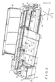
- the frame generally designated 12 includes an elongated stable base 14, a generally parallel elongated upper member 16, and an upright side member 18 connecting the base 14 and upper member 16.
- the upper member 16 includes a pivotable cover 20 which is pivotable between a closed position, as illustrated in FIG. 1, and a raised position, as illustrated in FIG. 2, which enables access to many of the working components of the plotter.
- Means for marking the sheet or chart 22 along the Y-axis, as it passes along the X-axis through the frame 12, in accordance with the signal received by the control mechanism, includes a Y-axis dual motor drive system.
- the system utilizes a drive belt 24 having each end thereof driven by a separate Y-axis motor 26 functionally connected thereto by a belt and pulley arrangement 28.
- a conventional pen carriage or marker holder 30 is slidably mounted on the horizontally extending support 32 and secured to the belt 24 for movement therewith. Both Y-axis motors 26 are driven together as a unit to produce Y-axis travel of the drive belt 24 and pen carriage 30 (as shown by arrows 33).
- the use of a dual motor drive system provides superior compliance of the drive belt relative to a single motor drive system, thus resulting in greater speed, accuracy and repeatability in positioning of the pen carriage.
- the pen carriage 30 is adapted to hold a special pen or marker 34 which plots points on the upper surface of sheet 22.
- the pen carriage under appropriate direction from the control mechanism, is capable of either lowering the pen 34 so that it is in contact with the upper surface of sheet 22 so as to produce markings thereon or lifting the pen in the opposite direction along the Z-axis to remove the pen from the upper surface of the sheet so that it cannot produce markings thereon.
- the Y-axis dual motors are adapted to drive the belt 24 so as to bring the pen carriage 30 all the way to the left until it is adjacent the pen carousel or storage means 36.
- the pen carousel 36 is equipped with a variety of pens 34 and, by coordinated activity of the pen carriage 30 and the pen carousel 36, a pen 34 currently carried by the pen carousel may be exchanged for another pen presently carried by the pen carousel. This enables a pen to be replaced when its ink supply becomes exhausted or when a pen of different color is to be employed, etc.
- the means for transporting a sheet or chart 22 through the frame 12 along the X-axis comprises a pair of axially aligned friction drives or rollers 54, 56 disposed adjacent the undersurface of the sheet adjacent respective opposed sides thereof.
- Each of the friction drives 54, 56 comprises a single small diameter rod having an outer end journaled in an outer bearing block assembly 58 and an inner end journaled in a common center bearing block assembly 60.
- a pair of bearing means 62, 64 are disposed adjacent the upper surface of the sheet 22 adjacent respective opposed sides thereof to engage the sheet and force it into engagement with the associated friction drives 54, 56.
- the left bearing means 62 is preferably a conventional fixed pinch roller
- the right bearing means 64 is preferably a conventional adjustable pinch roller slidable along horizontally extending support 32.
- a pair of X-axis motors 66, 68 drive the friction drives 54, 56 under independent control -- that is, with each variable speed drive motor 66, 68 being adapted to drive its respective friction drive 54, 56 at an independent rate of rotation.
- the motors 66, 68 are connected to the end portions of the drive shafts 54, 56 extending outwardly from the outer bearing block assemblies 58 by means of belt and pulley arrangements 70.
- outer bearing block assemblies 58 and the center bearing block assembly 60 cooperate to maintain the friction drives with their axes of rotation aligned with each other along the Y-axis and substantially transverse to the axis of transport of the sheet -- namely, the X-axis.
- the X-axis dual motor drive provides three features or advantages when compared to a conventional system.
- the two small motors are more economical than one large one.
- Second, slight, but normal manufacturing tolerance differences between the diameters of the two friction drives can be compensated for by varying the relative rotational speeds thereof. For example, a 0.001 inch difference of diameter between drive rollers of 2 inches circumference results in an error of 0.05 inch after a move of 34 inches.
- the X-axis dual motor drive permits the chart to be moved in a linear direction (indicated by arrow 72) when both drives are rotated in the same direction at the same effective speed (after compensation for drive diameter differentials), or in a rotational motion if the drives are driven differentially.
- this feature enables controlled skewing of the sheet by rotating of the drives at different effective speeds in the same direction, by rotating the drives at the same effective speed in different directions, or by rotating one drive and immobilizing the other.
- This enables an automatic chart alignment feature, as will be described next.
- the automatic chart alignment system enables a sheet 22 with a first linear side 80 to be aligned parallel to the X-axis by means of the aforementioned X-axis dual drive system and an electronic sensor 82 mounted on the frame 12 and capable of detecting the presence of the sheet 22 passing thereover.
- This sensor 82 is mounted a fixed distance X1 rearwardly from the drive rods 54, 56 in a location along the plotter X-axis corrresponding to the desired position of the chart edge.
- the sheet 22 can be correctly aligned with the plotter's Y-axis by just a few simple movements and use of sensor 82.
- the chart 22 is shown as viewed from the top of the plotter downwardly.
- the left and right drive rods 54, 56 are indicated schematically by the rectangles L and R, respectively.
- the chart 22 is initially loaded so that its left linear edge 80 is presumably not aligned with the plotter's X-axis.
- the left and right drive rods L and R may be run backward equally, if necessary to bring the front end 86 of the chart 22 a short distance in front of the drive rollers L and R.
- the means for aligning the first side of the sheet with the sensor 82 then swivels a first point A on the left edge 80 of the sheet 22 back and forth across the sensor (as indicated by arrow 87) to locate the edge 80 and align it substantially at the first point A with the sensor 82. More particularly, this is accomplished by immobilizing drive L (and thus the sheet edge segment between drive L and the fixed pinch roll 62) and running drive R first backward and then forward to cover and then uncover the sensor at point A. The left edge of the chart 22 at point A is now aligned with the sensor. (It will be appreciated that a cover and uncover operation is always performed any time an edge is being detected to maintain optimum accuracy since the sensor may have different trigger states for rising and falling edges.)
- the aligning means then advances the sheet 22 a given distance X1 by rotating both drives L and R equally forward (as indicated by arrow 89), thereby bringing point A against drive L.
- the aligning means then retains stationary the first point A while swiveling a second point B on the left side 80 of the sheet 22 back and forth across the sensor 82 to locate the left side and align it substantially at the second point B with the sensor. This is accomplished by immobilizing drive L and running drive R backward and forward to cover and uncover the sensor at point B. (Point A pivots between fixed pinch roll 62 and drive L, the pinch roll locking the location of point A against the immobilized drive L.)
- the aligning means additionally comprises means for advancing the sheet a second given distance X2 substantially greater than the first given distance X1.
- the aligning means then retains stationary the third point C on the left side 80 of the sheet 22 while swiveling the fourth point D on the left side of the sheet back and forth across the sensor 82 to locate the left side and align it substantially at the fourth point D with the sensor.
- drive L is immobilized and drive R is run backward and forward to cover and uncover the sensor at point D (by rotating the chart about immobilized pivot point C). This correlates with moving point D toward the sensor the distance Y2 and brings the left edge 80 to the "intermediate edge" position shown in dashed line in FIG. 6.
- the net angular rotation of drive R required to accomplish this is designated the movement R.
- the aligning means then advances the sheet the first given distance X1 by driving both drives L and R equally forward the first given distance X1 until the fourth point D is against drive L.
- the value R ⁇ is therefore calculated as -(R ⁇ X2)/(X1 + X2)
- the minus sign indicates that the direction is reversed so that if the movement R was a backward movement of drive R (a counter clockwise chart rotation as shown in FIG. 3), the movement R ⁇ will be a forward movement of drive R (a clockwise chart rotation as shwon in FIG. 3).
- the sign simply insures that the rotation of drive R is such as to move point C closer to the X-axis passing through the sensor.
- FIG. 7 the final parallelism accuracy can be expressed as (Y1 + Y1)/(X1 + X2), obviously an improvement over (Y1 + Y1)/X1.
- Chart alignment can be performed as part of chart loading procedures to insure proper orientation before a plot, during a plot to insure the accuracy of the plot, or, when using a continuous roll of media, between plots to insure proper alignment for each plot.
- the last mentioned procedure can be modified to start at the back of the chart with points A and B and go to the front of the chart with points C and D, as might be useful after spooling a chart forward off a roll and after loading of a chart from the front of the plotter.
- the alignment procedures encompass swiveling a sheet 22 by any differential driving of the two X-axis drive motors 66 and 68.
- One drive i.e., drive L on the same sheet side as sensor 82
- the latter has proven particularly useful in reducing the abrasion of the sheet surface during the alignment procedure.
- the senor 82 will include a pair of sensing means, one for detecting swiveling of the left edge 80 of sheet 22 and one for detecting passage of the front end 86 or rear end 88 of the sheet 22.
- the chart cutting mechanism utilizes a knife 34 ⁇ for cutting the sheet 22 along the Y-axis, the knife being configured and dimensioned to be received, held and returned by the pen holder or carriage 30 and held by the pen carousel or storage means 36 as a pen or marker 34.
- the knife 34 ⁇ is similar to a standard plotter pen and is normally stored in the pen carousel with the pens when not in use.
- FIG. 8 to better illustrate the knife 34 ⁇ , it is shown separate from the carriage 30, but connected thereto by a dashed line arrow.
- the pen carriage 30 retrieves the knife 34 ⁇ from the pen carousel 36, typically leaving the pen 34 in the pen carousel.
- the knife is provided with opposed grooves, one groove 90 mating with a key 92 in the pen carousel 36 and one groove 94 mating with a key 96 in the pen carriage 30.
- the blade of the knife extends a little further downwardly from the pen carriage to insure that the blade penetrates the sheet when the pen carriage is in its down orientation.
- the knife may be the same length as a pen and the control mechanism may simply lower the pen carriage further along the Z-axis when cutting is desired.
- a chart cutting operation is initiated by bringing the pen carriage close to the pen carousel and returning any pen in the pen carriage to its appropriate slot in the pen carousel.
- the pen carousel is then rotated until the knife is in appropriate position for the pen carriage, and the pen carriage then retrieves the knife.
- the chart is advanced to the cutting position, with the knife up, the pen carriage moves to the approximate center of the chart.
- the pen carriage is then lowered until the knife penetrates the chart, then the pen carriage is moved left through the edge of the paper, thereby making the first cut 100.
- the pen carriage is then raised and moved just past the approximate center of the chart.
- the pen carriage is again lowered until the knife penetrates the chart, then the pen carriage is moved right through the edge of the chart, thereby making the second cut 102.
- the chart is now supported only by the small tab of remaining material at the center of the chart.
- the pen carriage is then raised again and moved to the tab at the center of the chart.
- the pen carriage is then lowered until the knife penetrates the plane of the chart, and the pen carriage is then moved right (or left) so as to cut the remaining tab, thereby making the third cut 104.
- the directions of the various cuts are indicated by the arrows 100 ⁇ , 102 ⁇ and 104 ⁇ .
- the chart cutting mechanism first positions the knife in the chart to one side of a central segment of the chart and then moves it outwardly until it clears the sheet, next positions the knife in the sheet to the other side of the central segment of the chart and then moves it outwardly until it clears the sheet, and finally causes the knife to cut across the central segment.
- the chart is then free to drop into the chart handling mechanism while the pen carriage returns the knife to the pen carousel and retrieves a pen, thereby completing the cutting operation and returning the plotter to its previous state.
- the chart cutting mechanism preferably uses three cutting motions -- a first edge cut 100, a second edge cut 102, and a third center cut 104 -- to insure that the chart drops smoothly and accurately into the chart handling mechanism after cutting, obviously a different number of cutting motions may be used.
- Another preferred cutting pattern comprises a series of only two cuts, both outwardly in opposite directions from a center point of the chart.
- the cut chart handling mechanism is a rod and frame assembly 110 that can be extended and retracted from beneath the horizontal upper member 16 with a drive motor 112, this degree of movement being all that is required to retrieve and store a cut chart.
- the cut chart handling mechanism stores a given number of charts for a plotting system by successfully draping them over the rod, from which the charts can then be unloaded by the operator. Operation of the cut chart handling mechanism is, of course, synchronized with the other plotter operations, especially chart advance and chart cutting.
- the drive motor 112 initially moves the collecting rod or bar member 114 from its initial retracted position (as shown in FIGS. 1 and 2), wherein the bar member is disposed adjacent a back surface of the chart being transported and allows unimpeded fall of the front end 86 of the chart, to an intermediate extended position (as shown in FIG. 8), wherein the bar member is extended fully forward adjacent a front surface of the chart being transported, still allowing unimpeded fall of the chart.
- the bar member remains in the intermediate extended position until approximately half the chart length extends out the front of the plotter, behind and below the bar member.
- the motor 112 then moves the bar member from the intermediate extended position to its final retracted position (as shown in FIGS.
- the various actions of the plotter are coordinated by a central control mechanism, typically a microprocessor or microchip 120 contained in the upper member 16.
- the control mechanism controls action of the plotter along the plotter X, Y and Z axes. More particularly, the control mechanism compensates for variations in the effective diameters of the X-axis drive rollers and coordinates the activities thereof to produce the desires X-axis motion, whether that be a linear forward or backward motion or a swiveling of the sheet about a point by immobilization of one drive (thereby fixing the swivel point between the immobilized drive and the pinch roller) and backward and forward motion of the other drive.
- the control mechanism interprets the signal received by the plotter and accordingly coordinates the direction and extent of the motion of the Y-axis motors and hence the pen carriage. To this end, the control mechanism further controls rotation of the pen carousel or storage means to provide pen or knife means to the pen carriage. In its control of motion along the Z-axis, the control mechanism effects energization or de-energization of the solenoids which control the up and down orientation of the pen carriage, as necessary for marking and cutting.
- the present invention provides several mechanisms useful in both attended and unattended operation of the plotter.
- the X-axis drive mechanism not only avoids accidental skewing of the chart, but due to a low inertial load presented by the dual drives, is economically implemented.
- the automatic chart alignment mechanism requires only an edge aligning sensor and the aforementioned X-axis dual drive mechanism to enable charts to be accurately aligned with the plotter X-axis.
- the chart cutting mechanism requires generally only the modification of a marker to carry a knife in order to enable chart stock supplied in roll form to be accurately cut to a desired length for a plot.
- the cut chart handling mechanism provided at only a moderate extra cost, enables the retrieval and orderly storing of cut charts.
- a special feature of the present invention is a plotter incorporating all of these mechanisms so that charts may be fed without accidental skewing through the plotter, aligned, cut and stored without human intervention.
Landscapes
- Physics & Mathematics (AREA)
- General Physics & Mathematics (AREA)
- Handling Of Sheets (AREA)
- Handling Of Continuous Sheets Of Paper (AREA)
- Registering Or Overturning Sheets (AREA)
Applications Claiming Priority (2)
| Application Number | Priority Date | Filing Date | Title |
|---|---|---|---|
| US925067 | 1986-10-30 | ||
| US06/925,067 US4734716A (en) | 1986-10-30 | 1986-10-30 | Plotter and aligning method |
Publications (2)
| Publication Number | Publication Date |
|---|---|
| EP0266191A2 true EP0266191A2 (de) | 1988-05-04 |
| EP0266191A3 EP0266191A3 (de) | 1989-02-01 |
Family
ID=25451158
Family Applications (1)
| Application Number | Title | Priority Date | Filing Date |
|---|---|---|---|
| EP87309529A Withdrawn EP0266191A3 (de) | 1986-10-30 | 1987-10-28 | Ausrichteverfahren für Plotter |
Country Status (4)
| Country | Link |
|---|---|
| US (1) | US4734716A (de) |
| EP (1) | EP0266191A3 (de) |
| JP (1) | JPS63120699A (de) |
| CA (1) | CA1273615C (de) |
Cited By (1)
| Publication number | Priority date | Publication date | Assignee | Title |
|---|---|---|---|---|
| FR2642009A1 (fr) * | 1989-01-25 | 1990-07-27 | Schlumberger Ind Sa | Procede et dispositif pour le stockage automatique de dessins produits par une machine a dessiner |
Families Citing this family (17)
| Publication number | Priority date | Publication date | Assignee | Title |
|---|---|---|---|---|
| JPH02148392U (de) * | 1989-05-19 | 1990-12-17 | ||
| FR2657298B1 (fr) * | 1990-01-22 | 1995-03-10 | Oce Graphics France | Dispositif pour assurer le maintien d'un support d'impression sur un plateau de guidage dans la zone d'ecriture d'une machine a dessiner. |
| USD340066S (en) | 1991-01-22 | 1993-10-05 | Mutoh Industries Ltd. | Ink jet plotter |
| DE69117738T2 (de) * | 1991-05-10 | 1996-10-31 | Hewlett Packard Co | Schneidvorrichtung für Kurvenschreiber |
| USD339374S (en) | 1991-05-28 | 1993-09-14 | Calcomp Inc. | Pedestal-mounted case for a pen plotter |
| US5333005A (en) * | 1991-07-10 | 1994-07-26 | Summagraphics Corporation | Apparatus for raising and lowering plotter marking devices |
| USD357033S (en) | 1992-03-26 | 1995-04-04 | Sandco, Inc. | Pawl and ratchet for aligning continuous feed paper in a printer and embosser |
| USD347239S (en) | 1992-05-25 | 1994-05-24 | Fuji Photo Film Co., Ltd. | Ink jet printer |
| USD347240S (en) | 1992-06-26 | 1994-05-24 | Sandco, Inc. | Pawl and ratchet for aligning continuous feed paper in a printer and embosser |
| USD408848S (en) | 1997-03-03 | 1999-04-27 | Hewlett-Packard Company | Printer |
| USD407740S (en) | 1997-09-03 | 1999-04-06 | Fuji Photo Film Co., Ltd. | Printer |
| US6269995B1 (en) | 1998-04-29 | 2001-08-07 | Gerber Scientific Products, Inc. | Friction drive apparatus for strip material |
| US6283655B1 (en) * | 1998-06-30 | 2001-09-04 | Gerber Scientific Products, Inc. | Friction-feed plotter with laterally-movable drive roller, and related method for plotting on sheets of different widths |
| US6637634B1 (en) * | 1998-12-21 | 2003-10-28 | Gerber Scientific Products, Inc. | Methods for calibration and automatic alignment in friction drive apparatus |
| USD464080S1 (en) | 2001-02-20 | 2002-10-08 | Seiko Epson Corporation | Printer |
| US6533268B2 (en) * | 2001-07-27 | 2003-03-18 | Xerox Corporation | Printer sheet lateral registration and deskewing system |
| JP2004182414A (ja) * | 2002-12-04 | 2004-07-02 | Noritsu Koki Co Ltd | 画像記録装置 |
Family Cites Families (12)
| Publication number | Priority date | Publication date | Assignee | Title |
|---|---|---|---|---|
| US31684A (en) * | 1861-03-12 | Geo A Walker | Improvement in plows | |
| USRE31684F1 (en) | 1970-08-17 | 1985-08-27 | Milton Roy Co | X-y plotter |
| US3925786A (en) * | 1971-10-11 | 1975-12-09 | Bruker Physik Ag | Recorder with cutting mechanism |
| DE2238379C3 (de) * | 1972-08-04 | 1984-08-30 | Bayer Ag, 5090 Leverkusen | Verfahren zur Herstellung von Polyaminen |
| US3857525A (en) * | 1973-04-20 | 1974-12-31 | Gerber Scientific Instr Co | Plotting system |
| FR2285277A1 (fr) * | 1974-09-19 | 1976-04-16 | Pomagalski Sa | Chariot d'un appareil de sauvetage a freinage aerodynamique |
| US4216482A (en) * | 1979-01-02 | 1980-08-05 | Hewlett-Packard Company | Automatic paper alignment mechanism |
| US4384298A (en) * | 1980-10-24 | 1983-05-17 | Hewlett Packard Company | Plotter |
| GB2086045B (en) * | 1980-10-24 | 1984-12-19 | Hewlett Packard Co | An x-y plotter |
| US4598298A (en) * | 1984-05-09 | 1986-07-01 | Hewlett-Packard Company | Plotter having automatic sheet feeder |
| US4654675A (en) * | 1984-06-27 | 1987-03-31 | Mutoh Industry Ltd. | Paper feeding device for automatic drafting machine |
| DE3509925A1 (de) * | 1985-03-19 | 1986-10-16 | EMECO GmbH, 6000 Frankfurt | Zeichen- und/oder schneideinrichtung |
-
1986
- 1986-10-30 US US06/925,067 patent/US4734716A/en not_active Expired - Fee Related
-
1987
- 1987-10-21 CA CA549911A patent/CA1273615C/en not_active Expired
- 1987-10-28 EP EP87309529A patent/EP0266191A3/de not_active Withdrawn
- 1987-10-30 JP JP62273655A patent/JPS63120699A/ja active Pending
Cited By (1)
| Publication number | Priority date | Publication date | Assignee | Title |
|---|---|---|---|---|
| FR2642009A1 (fr) * | 1989-01-25 | 1990-07-27 | Schlumberger Ind Sa | Procede et dispositif pour le stockage automatique de dessins produits par une machine a dessiner |
Also Published As
| Publication number | Publication date |
|---|---|
| JPS63120699A (ja) | 1988-05-25 |
| US4734716A (en) | 1988-03-29 |
| EP0266191A3 (de) | 1989-02-01 |
| CA1273615A (en) | 1990-09-04 |
| CA1273615C (en) | 1990-09-04 |
Similar Documents
| Publication | Publication Date | Title |
|---|---|---|
| EP0266191A2 (de) | Ausrichteverfahren für Plotter | |
| US4285752A (en) | Automatic tape lay-up system | |
| US5846005A (en) | Label printer with cutter attachment | |
| EP3603907B1 (de) | Schneidvorrichtung | |
| JPH0741592B2 (ja) | シート材料切断装置および切断方法 | |
| JPS6038197A (ja) | シート材料インデツクス方法および装置 | |
| EP0113701A2 (de) | Drucker für Verkaufsstelle | |
| CA1254850A (en) | Paper loading system for use in a printer | |
| EP0163959B1 (de) | Verfahren und Apparat zum automatischen Ausrichten von Blattmaterial | |
| US4557786A (en) | Label scanner assembly for labelling machines | |
| GB2096197A (en) | Apparatus for depositing a web of material on a table | |
| JP7141345B2 (ja) | カッティング装置 | |
| TW509637B (en) | Material advance tracking system | |
| KR930011099B1 (ko) | 통장류 취급장치 및 방법 | |
| JPS5855270A (ja) | インサ−タプリンタの書式制御方式 | |
| JP2001171875A (ja) | アライメント印を有するウェブ及びそのウェブを給送・加工する装置 | |
| EP0036193A1 (de) | Vorrichtung zum Fördern des Bandes von Etikettendruckmaschinen oder ähnlichen Maschinen | |
| JP3050856B2 (ja) | シート材及びシート材送給処理装置 | |
| JPH08132388A (ja) | 画像形成装置の用紙カット装置 | |
| US5807457A (en) | Encodable strip attachment and removal apparatus | |
| JPH05508374A (ja) | ウエブ材料のストリップをスプールに巻き取る装置 | |
| US20020097291A1 (en) | Establishing and maintaining registration of an image forming system in the slow-scan axis | |
| JP2002346983A (ja) | 積載シートの断裁装置 | |
| JP5268440B2 (ja) | ミシンのボビンケースチェンジ方法および装置 | |
| JP2966413B2 (ja) | 磁気記録再生装置 |
Legal Events
| Date | Code | Title | Description |
|---|---|---|---|
| PUAI | Public reference made under article 153(3) epc to a published international application that has entered the european phase |
Free format text: ORIGINAL CODE: 0009012 |
|
| AK | Designated contracting states |
Kind code of ref document: A2 Designated state(s): AT BE CH DE ES FR GB GR IT LI LU NL SE |
|
| PUAL | Search report despatched |
Free format text: ORIGINAL CODE: 0009013 |
|
| AK | Designated contracting states |
Kind code of ref document: A3 Designated state(s): AT BE CH DE ES FR GB GR IT LI LU NL SE |
|
| RHK1 | Main classification (correction) |
Ipc: G06K 15/22 |
|
| 17P | Request for examination filed |
Effective date: 19890603 |
|
| 17Q | First examination report despatched |
Effective date: 19901115 |
|
| STAA | Information on the status of an ep patent application or granted ep patent |
Free format text: STATUS: THE APPLICATION IS DEEMED TO BE WITHDRAWN |
|
| 18D | Application deemed to be withdrawn |
Effective date: 19920220 |
|
| RIN1 | Information on inventor provided before grant (corrected) |
Inventor name: FREEMAN, MARVIN L. Inventor name: SILVERBERG, ERIC Inventor name: JOHNSON, ROBERT A. Inventor name: PARNELL, JAMES A. |