EP0266231A1 - Anordnung zur numerischen Erfassung eines von einem Stromtransformator mit sättigbarem Magnetkern stammenden Wechselstromes - Google Patents
Anordnung zur numerischen Erfassung eines von einem Stromtransformator mit sättigbarem Magnetkern stammenden Wechselstromes Download PDFInfo
- Publication number
- EP0266231A1 EP0266231A1 EP87402042A EP87402042A EP0266231A1 EP 0266231 A1 EP0266231 A1 EP 0266231A1 EP 87402042 A EP87402042 A EP 87402042A EP 87402042 A EP87402042 A EP 87402042A EP 0266231 A1 EP0266231 A1 EP 0266231A1
- Authority
- EP
- European Patent Office
- Prior art keywords
- current transformer
- current
- sampler
- filter
- alternating current
- Prior art date
- Legal status (The legal status is an assumption and is not a legal conclusion. Google has not performed a legal analysis and makes no representation as to the accuracy of the status listed.)
- Withdrawn
Links
Images

Classifications
-
- H—ELECTRICITY
- H01—ELECTRIC ELEMENTS
- H01F—MAGNETS; INDUCTANCES; TRANSFORMERS; SELECTION OF MATERIALS FOR THEIR MAGNETIC PROPERTIES
- H01F38/00—Adaptations of transformers or inductances for specific applications or functions
- H01F38/20—Instruments transformers
- H01F38/22—Instruments transformers for single phase AC
- H01F38/28—Current transformers
- H01F38/32—Circuit arrangements
-
- G—PHYSICS
- G01—MEASURING; TESTING
- G01R—MEASURING ELECTRIC VARIABLES; MEASURING MAGNETIC VARIABLES
- G01R19/00—Arrangements for measuring currents or voltages or for indicating presence or sign thereof
- G01R19/25—Arrangements for measuring currents or voltages or for indicating presence or sign thereof using digital measurement techniques
Definitions
- the present invention relates to digital circuits for analyzing alternating current at industrial frequency comprising as input a current transformer with saturable magnetic core.
- the digital processing of an alternating electric current at industrial frequency, 50 or 60 Hz begins with sampling and analog-digital conversion of the samples at a maximum frequency of the order of 500 Hz imposed by the speed of the converters usual analog-digital and by the durations of the calculations carried out subsequently on the digitized samples to deduce the fundamental properties of the current sine wave: amplitude, phase, asymmetry Vietnamese from which the triggering criteria are usually established protections.
- the current transformer which provides electrical isolation and a simple change of scale, is dimensioned to have, in normal operation, an unsaturated magnetic toroid and faithfully reproduce at the secondary the current waveform of sinuoidal shape applied to his primary.
- exceptional operating conditions which are those for which the protections must imperatively be triggered, it happens that the magnetic toroid of the current transformer becomes saturated causing the appearance on the secondary of a waveform in alternately positive pulses and negative which is poorly perceived through sampling and can even be completely ignored as soon as the width of the pulses becomes or falls below the sampling period.
- the present invention aims to avoid the aforementioned drawback by altering as little as possible the shape of the signal delivered by the current transformer when it is not saturated, this in order to improve the operating safety for the protection using digital signal processing without reducing their accuracy.
- It relates to a device for the digital acquisition of an alternating electric current from a toroidal current transformer magnetic comprising, following the current transformer, a sampler and, between the sampler and the current transformer, a selective analog bandpass filter centered on the frequency of the alternating current.
- the selective bandpass analog filter preferably has a selectivity on the order of 1.6 and a response time on the order of one period of the alternating current.
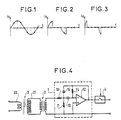
- a current transformer delivers to its secondary a current wave is of sinuoidal shape such as that represented in FIG. 1, which reproduces the shape of the current wave applied to the primary and whose a frequency sampling eight times greater than the fundamental frequency, represented by points pressed on the figure, gives a fairly faithful image.
- the magnetic toroid begins to saturate the shape of the current is issued from the secondary of the current transformer no longer follows that of the primary current ca r the secondary current is is canceled each time the magnetic toroid reaches its saturation and remains zero until 'at the next polarity change.
- the current wave coming from the secondary of the current transformer has, as shown in FIG. 2, saturation peaks of large width, of the order of a quarter of the fundamental period. In a frequency sampling eight times greater than the fundamental frequency there are at most three non-zero samples per period which makes saturation difficult to detect unless specific digital processing.
- the peaks in the secondary current of a current transformer caused by the saturation of the magnetic core have equal areas, of constant surface, their width decreasing and their amplitude increasing with saturation.
- the impedance adapter circuit 2 is a non-saturable, step-up transformer which brings the primary to a low impedance into which the secondary of the current transformer 3 flows.
- the analog band-pass filter 1 is centered on the fundamental frequency of the industrial alternating current passing through the primary 30 of the current transformer 3 which is assumed to be 50 Hz. It has a selectivity of 1.6 which corresponds to a pass band of 33 Hz wide enough not to alter the shape of the signal delivered to the secondary 31 of the current transformer 3 when the latter is not saturated, and a response time of the order of 20 ms corresponding to a period of the industrial alternating current passing through primary 30 of the current transformer 3 and adding only a short delay to the operation of any protection. It is produced in the form of an active bandpass filter of order 2 defined by the transfer function: At its input, it has a resistive divider bridge 10, 11 connected to the secondary of the transformer of the impedance adapter stage 2.
- An operational amplifier 12 placed after its inverting input connected via a capacitor 13 at the midpoint of the resistive bridge 10, 11 and its non-inverting input connected to ground. It is provided with a resistor 14 placed, in feedback, directly between its output and its inverting input, and with a capacitor 15 also placed in feedback, between its output and the midpoint of the resistive divider bridge 10, 11.
- FIG. 5 illustrates the behavior of the previous device in the case where the primary of the current transformer 3 is crossed by an alternating current step having an intensity equal to three times the limit value beyond which the magnetic toroid of the transformer is saturated of current 3.
- the solid line curve represents, as a function of time, the resulting voltage pulses, at the output of the impedance matching circuit 2, at the input of the analog filter 1 while the dashed curve represents, as a function of time, the voltage response of the filter 1 which is applied to the sampler 4.
- the amplitude scale adopted on the ordinate has for unit the peak limit value of the voltage available at the output of the impedance adapter stage 2 when the current transformer 3 is at the limit of saturation.
- the pressed points placed on the dashed curve gives an example of sampling the response of filter 1, executed at a frequency eight times greater than the fundamental frequency of the alternating current passing through the primary of the current transformer 3.
- Figure 6 shows the same curves as Figure 5 in the case where the primary of the current transformer 3 is crossed by a current industrial alternative with an intensity equal to forty times the limit value beyond which saturates the magnetic toroid of the current transformer 3.
- the signal restored by the filter 1 is in the form of a very distorted sinuoidal signal in which there is no longer a cancellation range of current which can lead to successive zero samples assimilable to an absence of current and where there are ranges greater than the limit value before saturation of long duration with respect to the sampling period which make it possible to perceive the overcurrents through sampling even in the event of saturation of the current transformer and thus ensuring flawless protection.
Landscapes
- Engineering & Computer Science (AREA)
- Power Engineering (AREA)
- Physics & Mathematics (AREA)
- General Physics & Mathematics (AREA)
- Dc Digital Transmission (AREA)
- Measurement Of Current Or Voltage (AREA)
Applications Claiming Priority (2)
| Application Number | Priority Date | Filing Date | Title |
|---|---|---|---|
| FR8612933A FR2603992B1 (fr) | 1986-09-16 | 1986-09-16 | Dispositif pour l'acquisition numerique d'un courant electrique alternatif issu d'un transformateur de courant a tore magnetique saturable |
| FR8612933 | 1986-09-16 |
Publications (1)
| Publication Number | Publication Date |
|---|---|
| EP0266231A1 true EP0266231A1 (de) | 1988-05-04 |
Family
ID=9338988
Family Applications (1)
| Application Number | Title | Priority Date | Filing Date |
|---|---|---|---|
| EP87402042A Withdrawn EP0266231A1 (de) | 1986-09-16 | 1987-09-14 | Anordnung zur numerischen Erfassung eines von einem Stromtransformator mit sättigbarem Magnetkern stammenden Wechselstromes |
Country Status (2)
| Country | Link |
|---|---|
| EP (1) | EP0266231A1 (de) |
| FR (1) | FR2603992B1 (de) |
Cited By (5)
| Publication number | Priority date | Publication date | Assignee | Title |
|---|---|---|---|---|
| EP0386604A3 (de) * | 1989-03-07 | 1991-07-24 | Zellweger Luwa Ag | Statischer Elektrizitätszähler |
| CN110187165A (zh) * | 2019-07-08 | 2019-08-30 | 西安创特电气科技有限公司 | 一种单一电流互感器取能与采样电路及控制方法 |
| CN113408232A (zh) * | 2021-06-18 | 2021-09-17 | 国网陕西省电力公司电力科学研究院 | 一种磁环工频饱和特性模拟方法 |
| CN113922787A (zh) * | 2021-10-08 | 2022-01-11 | 国网福建省电力有限公司营销服务中心 | 用于低压拓扑识别的信号采集与调理电路及方法 |
| CN120490951A (zh) * | 2025-07-16 | 2025-08-15 | 中广电器股份有限公司 | 一种低阻抗电压互感器的高精度性能测试处理方法及系统 |
Citations (4)
| Publication number | Priority date | Publication date | Assignee | Title |
|---|---|---|---|---|
| DE1616545A1 (de) * | 1968-03-01 | 1971-06-03 | Licentia Gmbh | Verfahren zur Messung einer Stromkomponente in einem Wechselstromkreis |
| EP0074297A1 (de) * | 1981-08-26 | 1983-03-16 | Merlin Gerin | Hybrider kompensierter Stromwandler |
| FR2575295A1 (fr) * | 1984-12-20 | 1986-06-27 | Electricite De France | Dispositif electrique auto-alimente et utilisant des transmissions par fibres optiques, destine a la mesure d'une grandeur physique |
| US4652810A (en) * | 1985-01-29 | 1987-03-24 | Yokogawa Hokushin Electric Corporation | Subminiature current transformer |
-
1986
- 1986-09-16 FR FR8612933A patent/FR2603992B1/fr not_active Expired
-
1987
- 1987-09-14 EP EP87402042A patent/EP0266231A1/de not_active Withdrawn
Patent Citations (4)
| Publication number | Priority date | Publication date | Assignee | Title |
|---|---|---|---|---|
| DE1616545A1 (de) * | 1968-03-01 | 1971-06-03 | Licentia Gmbh | Verfahren zur Messung einer Stromkomponente in einem Wechselstromkreis |
| EP0074297A1 (de) * | 1981-08-26 | 1983-03-16 | Merlin Gerin | Hybrider kompensierter Stromwandler |
| FR2575295A1 (fr) * | 1984-12-20 | 1986-06-27 | Electricite De France | Dispositif electrique auto-alimente et utilisant des transmissions par fibres optiques, destine a la mesure d'une grandeur physique |
| US4652810A (en) * | 1985-01-29 | 1987-03-24 | Yokogawa Hokushin Electric Corporation | Subminiature current transformer |
Non-Patent Citations (3)
| Title |
|---|
| ELECTRONICS & POWER, vol. 23, no. 1, janvier 1977, pages 52-55, Hitchin, GB; M. GROENENBOOM et al.: " Accurate measurement of d.c. and a.c. by transformer" * |
| IEEE TRANSACTIONS ON INSTRUMENTATION AND MEASUREMENT, vol. IM-19, no. 3, août 1970, pages 144-147, New York, US; F.J. EVANS et al.: "Use of asampling scheme to detect transient saturation in protective current transformers" * |
| TOUTE L'ELECTRONIQUE, no. 425, octobre 1977, pages 55-64, Paris, FR; M. QUERE: "Les filtres elliptiques" * |
Cited By (8)
| Publication number | Priority date | Publication date | Assignee | Title |
|---|---|---|---|---|
| EP0386604A3 (de) * | 1989-03-07 | 1991-07-24 | Zellweger Luwa Ag | Statischer Elektrizitätszähler |
| AU640914B2 (en) * | 1989-03-07 | 1993-09-09 | Zellweger Uster Ag | Static electricity meter |
| CN110187165A (zh) * | 2019-07-08 | 2019-08-30 | 西安创特电气科技有限公司 | 一种单一电流互感器取能与采样电路及控制方法 |
| CN110187165B (zh) * | 2019-07-08 | 2024-05-14 | 西安创特电气科技有限公司 | 一种单一电流互感器取能与采样电路及控制方法 |
| CN113408232A (zh) * | 2021-06-18 | 2021-09-17 | 国网陕西省电力公司电力科学研究院 | 一种磁环工频饱和特性模拟方法 |
| CN113408232B (zh) * | 2021-06-18 | 2023-09-19 | 国网陕西省电力公司电力科学研究院 | 一种磁环工频饱和特性模拟方法 |
| CN113922787A (zh) * | 2021-10-08 | 2022-01-11 | 国网福建省电力有限公司营销服务中心 | 用于低压拓扑识别的信号采集与调理电路及方法 |
| CN120490951A (zh) * | 2025-07-16 | 2025-08-15 | 中广电器股份有限公司 | 一种低阻抗电压互感器的高精度性能测试处理方法及系统 |
Also Published As
| Publication number | Publication date |
|---|---|
| FR2603992B1 (fr) | 1988-10-28 |
| FR2603992A1 (fr) | 1988-03-18 |
Similar Documents
| Publication | Publication Date | Title |
|---|---|---|
| CA1126852A (fr) | Dispositif de traitement d'un signal d'analyse d'image | |
| FR2850495A1 (fr) | Dispositif de protection differentielle et appareil de coupure electrique comportant un tel dispositif | |
| EP0019540A1 (de) | Vorrichtung zum Messen einer Flüssigkeitshöhe | |
| EP0412024B1 (de) | Vorrichtung zur Messung vom Effektivwert eines Signales, insbesondere zur Messung des Stromes in einem statischen Auslöser | |
| EP0092015A1 (de) | Ionisierungsvorrichtung | |
| EP0278193A1 (de) | Schaltung zum Messen des die Primärwicklung des Ausgangstransformators eines Wechselrichters durch fliessenden Gleichstromanteiles | |
| EP3462187B1 (de) | Spannungspräsenz-anzeigesystem in einem hochspannungsnetz | |
| EP0654604A1 (de) | Verfahren und Vorrichtung einer Spulenzündung mit zusätzlichen Entladungen zur Diagnose | |
| FR3132184A1 (fr) | Appareil électrique de protection d’une installation électrique en courants alternatif et/ou continu | |
| FR2669739A1 (fr) | Controleur d'isolement a precision amelioree. | |
| EP0544589A1 (de) | Gerät zur Messung des realen Lastfaktors eines elektrischen Generators | |
| FR2467390A1 (fr) | Debitmetre magnetique comportant un systeme amplificateur a plusieurs etages avec remise a zero automatique | |
| EP1084417B1 (de) | Elektrischer stromsensor mit hoher bandbreite | |
| EP0454542B1 (de) | Kontrollvorrichtung, die zur Messung der Wirksamkeit eines elektrischen Zaunes dient | |
| EP0285532B1 (de) | Fehlerdetektor für ein dreiphasiges Netz, das Lasten mit Vollwellzügen speist | |
| JP3062941B2 (ja) | ロゴスキーコイル用積分回路 | |
| EP0063520B1 (de) | Elektrischer Messumschalter für reaktive Impedanzen und eine damit ausgestattete Messbrücke | |
| FR2603992A1 (fr) | Dispositif pour l'acquisition numerique d'un courant electrique alternatif issu d'un transformateur de courant a tore magnetique saturable | |
| EP4567437B1 (de) | Messung der phase einer komplexen impedanz durch schwellenwert | |
| EP0554188B1 (de) | Gerät zur Messung elektrischer Grössen | |
| FR2688272A1 (fr) | Dispositif d'allumage electronique a bobine pour moteur a allumage commande. | |
| EP0369868A1 (de) | Messgerät für die gleichzeitige Messung von wenigstens zwei elektrischen Grössen | |
| EP0086158A1 (de) | Schaltung zur Versorgung einer Wirbelstromsonde | |
| FR2700208A1 (fr) | Dispositif pour la mesure d'une résistance d'isolement. | |
| EP0267502A1 (de) | Kompensation der Stromasymmetrie eines Messstromshunts |
Legal Events
| Date | Code | Title | Description |
|---|---|---|---|
| PUAI | Public reference made under article 153(3) epc to a published international application that has entered the european phase |
Free format text: ORIGINAL CODE: 0009012 |
|
| AK | Designated contracting states |
Kind code of ref document: A1 Designated state(s): CH DE FR GB IT LI SE |
|
| 17P | Request for examination filed |
Effective date: 19881102 |
|
| RAP1 | Party data changed (applicant data changed or rights of an application transferred) |
Owner name: GEC ALSTHOM SA |
|
| 17Q | First examination report despatched |
Effective date: 19910809 |
|
| STAA | Information on the status of an ep patent application or granted ep patent |
Free format text: STATUS: THE APPLICATION IS DEEMED TO BE WITHDRAWN |
|
| 18D | Application deemed to be withdrawn |
Effective date: 19911220 |
|
| RIN1 | Information on inventor provided before grant (corrected) |
Inventor name: EBERSOHL, GERARD Inventor name: FRAYCE, YVES |