EP0454542B1 - Kontrollvorrichtung, die zur Messung der Wirksamkeit eines elektrischen Zaunes dient - Google Patents
Kontrollvorrichtung, die zur Messung der Wirksamkeit eines elektrischen Zaunes dient Download PDFInfo
- Publication number
- EP0454542B1 EP0454542B1 EP91401012A EP91401012A EP0454542B1 EP 0454542 B1 EP0454542 B1 EP 0454542B1 EP 91401012 A EP91401012 A EP 91401012A EP 91401012 A EP91401012 A EP 91401012A EP 0454542 B1 EP0454542 B1 EP 0454542B1
- Authority
- EP
- European Patent Office
- Prior art keywords
- resistors
- voltage
- values
- current
- capacitor
- Prior art date
- Legal status (The legal status is an assumption and is not a legal conclusion. Google has not performed a legal analysis and makes no representation as to the accuracy of the status listed.)
- Expired - Lifetime
Links
- 239000004020 conductor Substances 0.000 claims abstract description 7
- 239000003990 capacitor Substances 0.000 claims description 16
- 241001465754 Metazoa Species 0.000 claims description 11
- 238000005259 measurement Methods 0.000 claims description 7
- 230000010354 integration Effects 0.000 claims description 6
- 238000000034 method Methods 0.000 claims description 6
- 238000010586 diagram Methods 0.000 description 2
- 235000021183 entrée Nutrition 0.000 description 2
- 230000001174 ascending effect Effects 0.000 description 1
- 238000002474 experimental method Methods 0.000 description 1
- 238000010438 heat treatment Methods 0.000 description 1
- 230000010355 oscillation Effects 0.000 description 1
- 230000001869 rapid Effects 0.000 description 1
- 230000003252 repetitive effect Effects 0.000 description 1
Images


Classifications
-
- H—ELECTRICITY
- H05—ELECTRIC TECHNIQUES NOT OTHERWISE PROVIDED FOR
- H05C—ELECTRIC CIRCUITS OR APPARATUS SPECIALLY DESIGNED FOR USE IN EQUIPMENT FOR KILLING, STUNNING, OR GUIDING LIVING BEINGS
- H05C3/00—Other circuits or apparatus
Definitions
- the present invention relates generally to electric fences used to close fields where animals graze so that they can be left unattended.
- the invention relates more particularly to a device for controlling the proper functioning of these fences.
- controllers make it possible to detect or measure the peak voltage existing between the terminals of an energizer, between two conducting wires, or between a conducting wire and the ground. Other types of controllers make it possible to measure a more or less integrated value over time of the pulse voltage.
- the magnitude representative of the pain felt by an animal or a man touching the conductors is mainly a function of the electrical energy which is dissipated in the body during the pulse.
- the measurement of the peak voltage of the pulse is therefore not very representative of the efficiency of the energizer, or of the electric fence line at the place where the measurement is made.
- the invention aims to propose a device whose "quadrature of V (t)" and “integration over time” parts are composed of passive elements (resistors, diodes, zener diodes, capacitors, etc.). ) stable over time and temperature, not very energy-hungry, and whose response time is extremely short.
- the invention relates to a control device used to measure the efficiency of an electric fence, the device measuring the energy of each pulse appearing at the output of the energizer or between two conductors of the fence and comprising two input terminals, means for generating a current from the voltage of the pulse applied between the input terminals, current which is proportional to a function approximating the square of the input voltage, and means for integrating over time the current thus generated.
- An electrical charge R c simulating the impedance of an animal touching the wires can be connected between the two input terminals of the controller, the ohmic value of R c being much smaller than the ohmic values of the resistors R n of the circuit d analysis and measurement.
- the integral of the current I (t) proportional to the square of the voltage can be obtained by charging a capacitor C i through a resistor R i such that the constant of time R i C i is much greater than the duration of the input pulse.
- the capacitor C i is discharged by an automatic reset device, a certain time after the pulse, after the peak voltage reached has been detected but before the next pulse appears.
- the capacitor C i can also be discharged by an automatic reset device only after a determined number of pulses.
- the discharge of the capacitor C i can be obtained by a manually operated switch.
- the pulse energy is read by connecting the capacitor to a display device, digital or needle, which indicates the peak value of the voltage of the capacitor C i reached at the end of the integration process or processes.
- a load R c is connected between the two input terminals of the controller.
- This load can be chosen close to 1000 ohms, a value which fairly well represents the impedance of the body and the contacts for an animal touching the wire.
- R2 and R3 form a divider bridge, R2 having sufficient values not to modify the charge R c appreciably. In the case where R3 has a value much smaller than R c , we can delete R2 and link R3 in series with R c .
- R2 and R3 form a divider bridge in order to work under voltages, at the terminals of R3, much lower than the input voltage V (t) which can reach 10,000 volts.
- a diode bridge D1, D2, D3, D4 makes it possible to rectify the oscillations of the input signal.
- an electrical system composed of the 4 blocks Q1, Q2, Q3, Q4. These 4 blocks allow signal analysis, display, and system reset.
- Q1 is a device which transforms the signal V (t) into an electric current I (t) proportional to the square of V (t).
- Q2 integrates the signal I (t) over time, and stores the information in the form of a charging voltage V2 of a capacitor C i which is proportional to: ⁇ I2 (t) dt # M x ⁇ (1 / R vs ) x V2 (t) dt.
- Q3 is a device which indicates, for example on a digital display, the voltage V2 reached at the terminals of C i after the end of each electrical pulse.
- Q4 is a device which makes it possible to completely discharge C i after the reading of its peak voltage has been made.
- Q4 can be designed, using the well-known means of electronics, to discharge the capacitor C i automatically a certain time after each pulse when the reading of V2 has been made.
- Q4 can also be designed to automatically unload C i only after a predetermined number of pulses so that the signal can be accumulated over several pulses.
- Q4 can be a manual device of the "push button" type on which the user presses in order to discharge C i , after a sufficient number of pulses to ensure a reliable reading of the display, in the case where the energy residual at the measurement location is small.
- FIG. 2 A possible embodiment of the electrical block Q1 is visible in Figure 2 in which Z1, Z2 ... Z n are clipping elements such as zener diodes or resistors varying with voltage.
- the elements Z n are arranged in ascending order of the values V n of their threshold voltages, from left to right.
- the first value V o of the element Z o is taken, in this example equal to zero, Z o , which is in fact a short circuit, is not shown.
- the device as shown in FIG. 2 makes it possible, when choosing the values V k of the voltage thresholds of the zener diodes, and the associated resistances R k , to obtain a current I (t) which is an increasing function G (V) represented in FIG. 3, composed of segments of lines each of which is a secant ("chord") of a curve F (V) at the points sought.
- R n 1 / K V1
- R1 1 / K V2
- R2 1 / [K (V3 - V1)] .
- R n-1 1 / [K (V n - V n-2 )]
- V V2 ;
- V V n-1
- V V n
- V n A fairly close choice of the values of V n then makes it possible to obtain an excellent approximation of the parabolic function.
- FIG. 4 represents a variant of the assembly of FIG. 2, in which the clipping elements are connected in series, which makes it possible to limit the number of types of zener diodes to be used and the value of their threshold voltage.
- FIG. 5 represents a well known integrator circuit, composed of a load resistor R i and a capacitor C i .
- This circuit makes it possible to obtain the integration of the current I (t) with a very good approximation insofar as the time constant R i C i is much less than the duration of each pulse.
Landscapes
- Life Sciences & Earth Sciences (AREA)
- Insects & Arthropods (AREA)
- Operating, Guiding And Securing Of Roll- Type Closing Members (AREA)
- Indicating And Signalling Devices For Elevators (AREA)
- Measurement Of Current Or Voltage (AREA)
- Housing For Livestock And Birds (AREA)
- Investigating Or Analyzing Materials By The Use Of Electric Means (AREA)
- Alarm Systems (AREA)
Claims (12)
- Kontrollvorrichtung, die zur Messung der Wirksamkeit eines elektrischen Zaunes dient und die Energie eines jeden am Ausgang des Elektrifizierers oder zwischen zwei Leitern des Zaunes auftretenden Pulses mißt, mit zwei Eingangsklemmen, Mitteln zur Erzeugung eines von der zwischen den Eingangsklemmen anliegenden Pulsspannung ausgehenden Stromes, der proportional zu einer sich dem Quadrat der Eingangsspannung annähernden Funktion ist, und Mitteln zur zeitlichen Integration des Stroms.
- Vorrichtung nach Anspruch 1, dadurch gekennzeichnet, daß die Näherung der Funktion "Quadrat der Spannung" durch Aufnahme eines Stromes l(t) ≈ K V²(t) am Ausgang eines Kreises erhalten wird, der Widerstände Rn und mit den Widerständen Rn in Reihe geschaltete Amplitudenbegrenzungselemente Zn, Leiter unter einer Spannung Vn, umfaßt und so beschaffen ist, daß- jeder Zweig Rn, Zn parallel geschaltet ist,- die Werte der Widerstände Rn und Elemente Zn Stufenwerte sind, entsprechend den Gleichungen:
Vo = o
Ro = 1 / K V₁
R₁ = 1 / K V₂
R₂ = 1 / [K(V₃-V₁)]
..........
Rn-1 = 1 / [K (Vn - Vn-2)],
wobei der Strom l(t) dann eine Funktion ist, die durch eine Reihe von Segmenten, oder "Sehnen", dargestellt werden kann, die die Parabel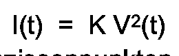
V = Vo
V = V₁
V = V₃
..........
V = Vn-2
V = Vn-1
V = Vn
schneiden. - Vorrichtung nach Anspruch 1, dadurch gekennzeichnet, daß die Näherung der Funktion "Quadrat der Spannung" durch Aufnahme eines Stromes l(t) ≈ K V²(t) am Ausgang eines Kreises erhalten wird, der Widerstände Rn und in Reihe mit den Widerständen Rn geschaltete Begrenzungselemente Zn, Leiter unter einer Spannung Vn, umfaßt und so beschaffen ist, daß- jeder Zweig Rn, Zn so geschaltet ist, daß die Widerstände Rn einen gemeinsamen Punkt haben, während jedes Element Zn den Punkt hat, der nicht mit dem Widerstand Rn gemeinsam ist, aber mit dem Punkt verbunden ist, der dem Widerstand Rn-1 und Zn-1 gemeinsam ist,- die Werte der Widerstände Rn und Elemente Zn Stufenwerte sind, entsprechend den Gleichungen:
Vo = o
Ro = 1 / K V₁
R₁ = 1 / [K ( V₂ + V₁)]
R₂ = 1 / [K (V₃ + V₂)]
..........
Rn-1 = 1 / [K (Vn + Vn-1)]
wobei der Strom l(t) dann eine Funktion ist, die durch eine Reihe von Segmenten, oder "Sehnen", wiedergegeben werden kann, die die Parabel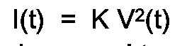
V = Vo
V = V₁ + V₂
V = V₁ + V₂ + V₃
.............
V = V₁ + V₂ + V₃ + ... + Vn-2
V = V₁ + V₂ + V₃ + ... + Vn-1
V = V₁ + V₂ + V₃ + ... + Vn
schneiden. - Vorrichtung nach einem der Ansprüche 2 oder 3, dadurch gekennzeichnet, daß die Begrenzungselemente Zn Zenerdioden oder mit der Spannung veränderbare Widerstände sind.
- Vorrichtung nach Anspruch 2, dadurch gekennzeichnet, daß die Werte Vn die Werte einer arithmetischen Folge mit dem ersten Glied 0 und dem Argument V₀ sind, wohingegen die Werte der Widerstände Rn gleich sind, mit Ausnahme von R₀, der einen doppelten Wert von R₁ = R₂ = R₃ = ... = Rn hat.
- Vorrichtung nach Anspruch 3, dadurch gekennzeichnet, daß die Werte von Vn alle identisch sind, mit Ausnahme von V₀, der einen Wert Null hat, wohingegen die Werte der Widerstände Rn gleich sind, bis auf R₀, der einen doppelten Wert von R₁ = R₂ = R₃ = ... = Rn hat.
- Vorrichtung nach einem der Ansprüche 1 bis 6, dadurch gekennzeichnet, daß eine elektrische Last Rc, die die Impedanz eines die Drähte berührenden Tieres simuliert, zwischen die beiden Eingangsklemmen des Kontrollgerätes geschaltet ist, wobei der ohmsche Wert von Rc sehr viel kleiner ist, als die ohmschen Werte der Widerstände Rn des Prüf- und Meßkreises.
- Vorrichtung nach einem der Ansprüche 1 bis 7, dadurch gekennzeichnet, daß das Integral des zum Quadrat der Spannung proportionalen Stromes l(t) mittels der Ladung eines Kondensators Ci über einen Widerstand Ri erhalten wird, wobei die Zeitkonstante Ri·Ci sehr viel größer als die Dauer des Eingangspulses ist.
- Vorrichtung nach Anspruch 8, dadurch gekennzeichnet, daß der Kondensator Ci durch eine automatische Nullstelleinrichtung entladen wird, und zwar zu einer bestimmten Zeit nach dem Puls, nachdem die erreichte Spitzenspannung aufgenommen worden ist, jedoch bevor der folgende Puls auftritt.
- Vorrichtung nach Anspruch 8, dadurch gekennzeichnet, daß der Kondensator Ci nur nach einer bestimmten Anzahl von Pulsen durch Eine automatische Nullstelleinrichtung entladen wird.
- Vorrichtung nach Anspruch 8, dadurch gekennzeichnet, daß der Kondensator Ci durch einen manuell bedienbaren Schalter entladen wird.
- Vorrichtung nach einem der Ansprüche 7 bis 11, dadurch gekennzeichnet, daß der Kondensator mit einem numerischen oder Zeigeranzeigegerät verbunden ist, das den zum Ende des oder der Intergrationsprozesse erreichten Spitzenwert der Spannung des Kondensators Ci anzeigt.
Applications Claiming Priority (2)
| Application Number | Priority Date | Filing Date | Title |
|---|---|---|---|
| FR9005245A FR2661505B1 (fr) | 1990-04-25 | 1990-04-25 | Dispositif de controle servant a mesurer l'efficacite d'une cloture electrique. |
| FR9005245 | 1990-04-25 |
Publications (2)
| Publication Number | Publication Date |
|---|---|
| EP0454542A1 EP0454542A1 (de) | 1991-10-30 |
| EP0454542B1 true EP0454542B1 (de) | 1995-03-15 |
Family
ID=9396055
Family Applications (1)
| Application Number | Title | Priority Date | Filing Date |
|---|---|---|---|
| EP91401012A Expired - Lifetime EP0454542B1 (de) | 1990-04-25 | 1991-04-17 | Kontrollvorrichtung, die zur Messung der Wirksamkeit eines elektrischen Zaunes dient |
Country Status (4)
| Country | Link |
|---|---|
| EP (1) | EP0454542B1 (de) |
| AT (1) | ATE120068T1 (de) |
| DE (1) | DE69108089T2 (de) |
| FR (1) | FR2661505B1 (de) |
Families Citing this family (3)
| Publication number | Priority date | Publication date | Assignee | Title |
|---|---|---|---|---|
| DE4115630A1 (de) * | 1991-05-14 | 1992-11-19 | Ako Werke Gmbh & Co | Schaltungsanordnung zur ueberwachung eines weidezaunes |
| FR2817443B1 (fr) * | 2000-11-30 | 2003-02-21 | Lacme | Dispositif de controle de l'efficacite d'une cloture electrique |
| DE202009015870U1 (de) * | 2009-11-20 | 2011-04-07 | Patura Kg | Vorrichtung zur Ermittlung eines Zustands einer Elektrozaunanlage |
Family Cites Families (3)
| Publication number | Priority date | Publication date | Assignee | Title |
|---|---|---|---|---|
| US3873847A (en) * | 1974-02-19 | 1975-03-25 | John H Finch | Control system for an electrified fence |
| US4523187A (en) * | 1980-08-29 | 1985-06-11 | Norman W. Hutchinson & Sons Pty. Ltd. | Alarm system for electric fences |
| US4725825A (en) * | 1986-03-17 | 1988-02-16 | Amco Partnership | Electric fence voltage indicator light |
-
1990
- 1990-04-25 FR FR9005245A patent/FR2661505B1/fr not_active Expired - Fee Related
-
1991
- 1991-04-17 AT AT91401012T patent/ATE120068T1/de not_active IP Right Cessation
- 1991-04-17 DE DE69108089T patent/DE69108089T2/de not_active Expired - Fee Related
- 1991-04-17 EP EP91401012A patent/EP0454542B1/de not_active Expired - Lifetime
Also Published As
| Publication number | Publication date |
|---|---|
| ATE120068T1 (de) | 1995-04-15 |
| DE69108089D1 (de) | 1995-04-20 |
| DE69108089T2 (de) | 1995-10-12 |
| FR2661505A1 (fr) | 1991-10-31 |
| FR2661505B1 (fr) | 1993-06-18 |
| EP0454542A1 (de) | 1991-10-30 |
Similar Documents
| Publication | Publication Date | Title |
|---|---|---|
| EP0389383B1 (de) | Schaltung und Verfahren zur Feststellung eines elektrischen Stromflusses in einem MOS-Transistor | |
| FR2702044A1 (fr) | Circuit de traitement pour signal de sortie de capteur analogique résistif, notamment pour jauge de carburant sur véhicule automobile et systèmes équipés. | |
| FR2605415A1 (fr) | Appareil de controle de l'etat de charge d'une pile | |
| EP0454542B1 (de) | Kontrollvorrichtung, die zur Messung der Wirksamkeit eines elektrischen Zaunes dient | |
| EP0092015A1 (de) | Ionisierungsvorrichtung | |
| EP0544589B1 (de) | Gerät zur Messung des realen Lastfaktors eines elektrischen Generators | |
| EP0011534B1 (de) | Verfahren und Vorrichtung zur Verarbeitung von analogischen, insbesondere pseudoperiodischen Signalen | |
| FR2538193A1 (fr) | Interface de sortie pour circuit logique a trois etats dans un circuit integre a transistors mos | |
| EP0274303A1 (de) | Wechselrichtergeneratorregelungssystem zur Induktionsspeisung einer Last | |
| FR2467407A1 (fr) | Dispositif de mesure des valeurs cretes d'un phenomene non periodique a recurrence faible | |
| EP0489665A1 (de) | Anordnung zur Isolationskontrolle mit erhöhter Genauigkeit | |
| FR2518850A1 (fr) | Systeme de reglage d'amplitude | |
| EP0424280B1 (de) | Elektronische Ansteuerungsschaltung für einen gleichstromgespeisten Schwingmotor | |
| EP0119110B1 (de) | Stellungsdetektor mit potentiometrischem Fühler insbesondere für Mehrrichtungswählschalter | |
| EP0025377B1 (de) | Schaltvorrichtung für eine Speicherkapazität, Integrator und Abtastkreis mit einer solchen Vorrichtung | |
| EP0266231A1 (de) | Anordnung zur numerischen Erfassung eines von einem Stromtransformator mit sättigbarem Magnetkern stammenden Wechselstromes | |
| EP0678751A1 (de) | Detektorvorrichtung für micht-flüchtige Änderungen einer Versorgungsspannung | |
| FR2489060A1 (fr) | Dispositif de detection d'erreurs d'un signal en code ternaire | |
| FR2802366A1 (fr) | Bascule analogique a commande par impulsions | |
| EP0280616B1 (de) | Vorrichtung zur Speisung elektrischer Energie für ein Kabel und seine Anwendung | |
| EP0068938A1 (de) | Logischer Erzeuger von periodischen Signalen | |
| FR2524737A1 (fr) | Dispositif recepteur pour la telecommande par impulsions | |
| FR2817443A1 (fr) | Dispositif de controle de l'efficacite d'une cloture electrique | |
| EP0540379A1 (de) | Zentralisierter Differentialschutzschalter | |
| FR2630548A1 (fr) | Dispositif de mesure de resistance electrique |
Legal Events
| Date | Code | Title | Description |
|---|---|---|---|
| PUAI | Public reference made under article 153(3) epc to a published international application that has entered the european phase |
Free format text: ORIGINAL CODE: 0009012 |
|
| AK | Designated contracting states |
Kind code of ref document: A1 Designated state(s): AT BE CH DE FR LI NL |
|
| 17P | Request for examination filed |
Effective date: 19911213 |
|
| 17Q | First examination report despatched |
Effective date: 19940210 |
|
| RAP1 | Party data changed (applicant data changed or rights of an application transferred) |
Owner name: HAMM, VALERY |
|
| GRAA | (expected) grant |
Free format text: ORIGINAL CODE: 0009210 |
|
| AK | Designated contracting states |
Kind code of ref document: B1 Designated state(s): AT BE CH DE FR LI NL |
|
| REF | Corresponds to: |
Ref document number: 120068 Country of ref document: AT Date of ref document: 19950415 Kind code of ref document: T |
|
| REF | Corresponds to: |
Ref document number: 69108089 Country of ref document: DE Date of ref document: 19950420 |
|
| PLBE | No opposition filed within time limit |
Free format text: ORIGINAL CODE: 0009261 |
|
| STAA | Information on the status of an ep patent application or granted ep patent |
Free format text: STATUS: NO OPPOSITION FILED WITHIN TIME LIMIT |
|
| 26N | No opposition filed | ||
| PGFP | Annual fee paid to national office [announced via postgrant information from national office to epo] |
Ref country code: BE Payment date: 20010417 Year of fee payment: 11 |
|
| PGFP | Annual fee paid to national office [announced via postgrant information from national office to epo] |
Ref country code: AT Payment date: 20010427 Year of fee payment: 11 Ref country code: CH Payment date: 20010427 Year of fee payment: 11 |
|
| PGFP | Annual fee paid to national office [announced via postgrant information from national office to epo] |
Ref country code: NL Payment date: 20010430 Year of fee payment: 11 |
|
| PG25 | Lapsed in a contracting state [announced via postgrant information from national office to epo] |
Ref country code: AT Free format text: LAPSE BECAUSE OF NON-PAYMENT OF DUE FEES Effective date: 20020417 |
|
| PG25 | Lapsed in a contracting state [announced via postgrant information from national office to epo] |
Ref country code: BE Free format text: LAPSE BECAUSE OF NON-PAYMENT OF DUE FEES Effective date: 20020430 Ref country code: CH Free format text: LAPSE BECAUSE OF NON-PAYMENT OF DUE FEES Effective date: 20020430 Ref country code: LI Free format text: LAPSE BECAUSE OF NON-PAYMENT OF DUE FEES Effective date: 20020430 |
|
| PG25 | Lapsed in a contracting state [announced via postgrant information from national office to epo] |
Ref country code: NL Free format text: LAPSE BECAUSE OF NON-PAYMENT OF DUE FEES Effective date: 20021101 |
|
| REG | Reference to a national code |
Ref country code: CH Ref legal event code: PL |
|
| NLV4 | Nl: lapsed or anulled due to non-payment of the annual fee |
Effective date: 20021101 |
|
| PGFP | Annual fee paid to national office [announced via postgrant information from national office to epo] |
Ref country code: DE Payment date: 20080418 Year of fee payment: 18 |
|
| PGFP | Annual fee paid to national office [announced via postgrant information from national office to epo] |
Ref country code: FR Payment date: 20090330 Year of fee payment: 19 |
|
| PG25 | Lapsed in a contracting state [announced via postgrant information from national office to epo] |
Ref country code: DE Free format text: LAPSE BECAUSE OF NON-PAYMENT OF DUE FEES Effective date: 20091103 |
|
| REG | Reference to a national code |
Ref country code: FR Ref legal event code: ST Effective date: 20101230 |
|
| PG25 | Lapsed in a contracting state [announced via postgrant information from national office to epo] |
Ref country code: FR Free format text: LAPSE BECAUSE OF NON-PAYMENT OF DUE FEES Effective date: 20100430 |