EP0266295A1 - System für automatische Realisierung landwirtschaftlicher Arbeit, wie Rasenmähen - Google Patents
System für automatische Realisierung landwirtschaftlicher Arbeit, wie Rasenmähen Download PDFInfo
- Publication number
- EP0266295A1 EP0266295A1 EP87480012A EP87480012A EP0266295A1 EP 0266295 A1 EP0266295 A1 EP 0266295A1 EP 87480012 A EP87480012 A EP 87480012A EP 87480012 A EP87480012 A EP 87480012A EP 0266295 A1 EP0266295 A1 EP 0266295A1
- Authority
- EP
- European Patent Office
- Prior art keywords
- vehicle
- drive
- tube
- guide
- guide rail
- Prior art date
- Legal status (The legal status is an assumption and is not a legal conclusion. Google has not performed a legal analysis and makes no representation as to the accuracy of the status listed.)
- Withdrawn
Links
- 238000005096 rolling process Methods 0.000 claims description 7
- 239000013013 elastic material Substances 0.000 claims description 4
- 230000007935 neutral effect Effects 0.000 claims description 3
- 230000000694 effects Effects 0.000 description 3
- 229920003023 plastic Polymers 0.000 description 2
- 239000004033 plastic Substances 0.000 description 2
- 241001494496 Leersia Species 0.000 description 1
- 239000004698 Polyethylene Substances 0.000 description 1
- 238000004873 anchoring Methods 0.000 description 1
- 230000008878 coupling Effects 0.000 description 1
- 238000010168 coupling process Methods 0.000 description 1
- 238000005859 coupling reaction Methods 0.000 description 1
- 238000010586 diagram Methods 0.000 description 1
- 230000004048 modification Effects 0.000 description 1
- 238000012986 modification Methods 0.000 description 1
- -1 polyethylene Polymers 0.000 description 1
- 229920000573 polyethylene Polymers 0.000 description 1
- 230000035939 shock Effects 0.000 description 1
- 239000007787 solid Substances 0.000 description 1
- 238000004804 winding Methods 0.000 description 1
Images


Classifications
-
- A—HUMAN NECESSITIES
- A01—AGRICULTURE; FORESTRY; ANIMAL HUSBANDRY; HUNTING; TRAPPING; FISHING
- A01D—HARVESTING; MOWING
- A01D34/00—Mowers; Mowing apparatus of harvesters
- A01D34/006—Control or measuring arrangements
- A01D34/008—Control or measuring arrangements for automated or remotely controlled operation
-
- A—HUMAN NECESSITIES
- A01—AGRICULTURE; FORESTRY; ANIMAL HUSBANDRY; HUNTING; TRAPPING; FISHING
- A01B—SOIL WORKING IN AGRICULTURE OR FORESTRY; PARTS, DETAILS, OR ACCESSORIES OF AGRICULTURAL MACHINES OR IMPLEMENTS, IN GENERAL
- A01B69/00—Steering of agricultural machines or implements; Guiding agricultural machines or implements on a desired track
- A01B69/007—Steering or guiding of agricultural vehicles, e.g. steering of the tractor to keep the plough in the furrow
- A01B69/008—Steering or guiding of agricultural vehicles, e.g. steering of the tractor to keep the plough in the furrow automatic
-
- B—PERFORMING OPERATIONS; TRANSPORTING
- B62—LAND VEHICLES FOR TRAVELLING OTHERWISE THAN ON RAILS
- B62D—MOTOR VEHICLES; TRAILERS
- B62D1/00—Steering controls, i.e. means for initiating a change of direction of the vehicle
- B62D1/24—Steering controls, i.e. means for initiating a change of direction of the vehicle not vehicle-mounted
- B62D1/26—Steering controls, i.e. means for initiating a change of direction of the vehicle not vehicle-mounted mechanical, e.g. by a non-load-bearing guide
-
- A—HUMAN NECESSITIES
- A01—AGRICULTURE; FORESTRY; ANIMAL HUSBANDRY; HUNTING; TRAPPING; FISHING
- A01D—HARVESTING; MOWING
- A01D2101/00—Lawn-mowers
-
- Y—GENERAL TAGGING OF NEW TECHNOLOGICAL DEVELOPMENTS; GENERAL TAGGING OF CROSS-SECTIONAL TECHNOLOGIES SPANNING OVER SEVERAL SECTIONS OF THE IPC; TECHNICAL SUBJECTS COVERED BY FORMER USPC CROSS-REFERENCE ART COLLECTIONS [XRACs] AND DIGESTS
- Y10—TECHNICAL SUBJECTS COVERED BY FORMER USPC
- Y10S—TECHNICAL SUBJECTS COVERED BY FORMER USPC CROSS-REFERENCE ART COLLECTIONS [XRACs] AND DIGESTS
- Y10S56/00—Harvesters
- Y10S56/15—Condition responsive
Definitions
- the present invention relates to a system for automatically carrying out agricultural work such as mowing lawns.
- Certain agricultural work, and more particularly domestic work such as mowing the lawn, is tedious and tiring to carry out and must moreover be carried out very regularly.
- a lawn needs to be mowed at least once a week.
- the lawn takes on an abandoned and unsightly appearance.
- the mowing operation which follows such an absence is always much longer and much more painful than a normal mowing carried out on a regular basis.
- the present invention aims to provide such a system which can be installed without difficulty on a ground such as a lawn, and which is sufficiently simple and inexpensive to be able to be acquired by individuals.
- the invention relates to a system for the automatic performance of agricultural work such as mowing the lawn, characterized in that it comprises in combination a guide rail substantially buried in the ground, and an agricultural vehicle such as a lawn mower, provided with a support frame, at least one tool such as a cutter bar, drive means and guide means mounted movably on said support frame and arranged to cooperate with the guide rail so as to cause said vehicle to follow substantially the guide rail.
- said drive means are drive and direction means and said vehicle is further provided with control means for controlling said drive and direction means as a function of the relative position of the means guide relative to the support frame.
- the guide rail can advantageously be made in the form of a tube of relatively elastic material, for example a plastic pipe, split along its upper generatrix, said guide means comprising a guide member arranged to move at the interior of said tube by being driven by said vehicle via a support member passing through the slot of this tube.
- the support member may for example comprise a profiled blade at one end of which said guide member is mounted, said blade being mounted at its other end in an articulated manner relative to the chassis of the vehicle.
- said drive and steering means comprise two tracks and the control means comprise means for selectively ceasing the drive of one of the tracks when the guide means deviate from a neutral position predetermined with respect to the chassis.
- the drive and steering means may comprise two electric motors arranged to each drive one of the tracks, said means for selectively ceasing the drive of one of the tracks then comprising two switches each arranged in the supply circuit of one of the motors and whose actuating member is arranged to cooperate with a cam mounted on said guide means.
- said support frame is supported on the ground by means of a front stand carrying at its lower end a guide member arranged to cooperate with the guide rail, and said vehicle is provided with '' a drive motor mounted on the support frame and two rear side running gear, said running gear being arranged to be driven by said drive motor via a differential.
- differential means not only the mechanical device generally known by this name, but also other devices making it possible to drive two rolling members simultaneously at possibly different speeds.
- the drive of the rolling members two DC motors whose windings are mounted in series, each of the motors driving one of the rolling members.
- said guide rail also comprises a tube of relatively elastic material split along its upper generatrix and said guide member is arranged to move inside said tube by being pushed by said vehicle by means of said stand passing through the slot of this tube.
- This stand can for example be constituted by a profiled blade mounted at its upper end pivoting with respect to the chassis of the vehicle around a substantially vertical axis.
- the use of electrical energy for driving the vehicle makes it possible to automate without difficulty, not only the advance of the vehicle, but also the whole of its working cycle. It suffices to provide a programmer ensuring the departure of the vehicle along its guide rail at predetermined hours and days from a departure and arrival station.
- the vehicle can then be provided with a battery allowing the supply of its electric motors, and a battery charger is provided at the departure and arrival station to which the vehicle is automatically connected at the end of its cycle of job.
- photovoltaic cell panels can be mounted directly on the vehicle itself.
- the vehicle may advantageously include a front cutter bar arranged along its front edge.
- a front cutter bar arranged along its front edge.
- this front blade occupies only one width limited.
- At least one cutter bar mounted laterally on the vehicle support frame can be provided, means being provided for retracting said lateral cutter bar in shock on an obstacle.
- This lateral cutter bar can for example be mounted for rotation about a substantially vertical axis, integral with the chassis, so as to be able to pivot backwards in the event of an impact, against the action of return means arranged to bring the cutter bar in its normal lateral position after passing the obstacle.
- two lateral cutter bars are provided, each disposed on one of the sides of the vehicle and arranged so that they can be retracted simultaneously.
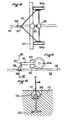
- the system according to the first embodiment of the invention generally comprises a vehicle 1 forming a lawn mower, and a pipe 2 constituting a rail buried in the ground 3 of a lawn .
- the vehicle 1 is provided with two tracks 4a and 4b driven respectively by electric motors 5a and 5b.
- the chassis 6 of the vehicle 1 supports a front cutter bar 7 whose blade 8 is driven by an electric motor 9, and two lateral cutter bars 10a and 10b whose blades 11a and 11b are respectively driven by electric motors 12a and 12b .
- a battery 13 enables the electric motors 5a, 5b, 9, 12a and 12b to be powered.
- the motors 12a and 12b drive the blades 11a and 11b using a rod 14 and crank 15 device ( Figures 6 and 7).
- Each lateral cutter bar 10a and 10b is mounted at its end closest to the axis of the vehicle 1 on arms 16a and 16b respectively, pivoting around an axis 17 secured to the chassis 6.
- the cutter bars can thus pivot backwards around axis 17, as shown by arrows F in Figure 2.
- Return springs 18 mounted on the axis 17 allow the cutter bars to be brought forward to their lateral position where they are in abutment on locking fingers 19 solid areas of the chassis 6.
- the vehicle 1 further comprises at its front part a bumper 20 provided with a general switch (not shown) making it possible, in the event of a frontal impact, to cut off the supply of all the electric motors.
- Each cutter bar also includes a front bumper 21 which, when the cutter bar encounters an obstacle, reacts by pivoting the corresponding bar backwards in the direction of the arrow F.
- the cutter bars are further provided at their end furthest from the axis of the vehicle 1 with a roller 22 allowing the cutting height to be adjusted by means of a crank 23, and a roller 24 with a vertical axis allowing a regular progression of the cutter bar when the vehicle 1 moves along a wall or a fence for example.
- the axis 17 is eccentric relative to the median plane of the vehicle 1 and that the arms 16a and 16b consequently have a different length. It follows that the two cutter bars 10a and 10b can be pivoted simultaneously towards the rear in the case where the vehicle 1 runs alongside two obstacles located one to its right, the other to its left.
- the vehicle guiding device 1 will now be described with particular reference to FIGS. 3, 4, 5 and 8.
- a drawbar 25 is freely mounted at one of its ends on a yoke of the chassis 6 using a pin 26.
- a support blade 27 is mounted rotating about an axis 28, and receives at its end opposite the axis 28 a profiled guide member 29 capable of sliding in the tube 2.
- the blade 27 In the vicinity of the axis 28, the blade 27 carries a cam 30 carrying two cam surfaces 31a and 31b. Each cam surface 31a and 31b is arranged to cooperate respectively with a cam follower formed by the end of the actuating member 32a and 32b of switches 33a and 33b.
- the switches 33a and 33b are mounted on a plate 34 secured to the end of the coupling arm 25 opposite the axis 26.
- the switches 33a and 33b make it possible, when they are in their normal position shown in FIG. 8, to supply the motors 5a and 5b from the battery 13 respectively. If the blade of the support 27 is moved, for example in the direction of the arrow F1 in FIG. 3, which corresponds to a turn of the tube 2 in the direction opposite to the arrow F1, the switch 33b is actuated by the cam 30 , which has the effect of causing its tilting symbolized in Figure 8 by the arrow F2. The motor 5b is thus no longer supplied, causing the track 4b to stop, which has the effect of causing the vehicle 1 to initiate a turn causing it to follow the tube 2.
- the pipe 2 made for example of polyethylene, is split along its upper generatrix 35, so as to allow passage to the guide blade 27 which is profiled so as to open without effort during its passage the edges of the slot 35.
- the tube 2 also has a rib 36 which makes it possible to ensure that the slot 35 covers well in the upper part of the tube 2 and also allows the tube to be anchored in the ground using stakes 37.
- FIG. 8 represents a lawn 38 under the surface of which is buried a guide tube 2 as described above.
- This tube is folded in a zig-zag so that, when the vehicle 1 travels through it, its cutter bars cover practically the entire surface of the ground 38.
- a stop and start station 39 is provided in a corner of the ground 38 and is equipped with a programmer and a battery charger (not shown).
- Two turning loops 40 are provided at the stop and start station 39 at each end of the tube 2. Thus, the successive mowing operations are carried out each time in the opposite direction to the previous time. Junction pieces 41 and crossing pieces 42 are provided for this purpose.
- the vehicle 1 moves along the tube 2 in the direction of the arrow F3 for example.
- the cam 30 is in its neutral position shown in FIG. 3, and the motors of the two tracks are powered.
- the vehicle deviates for example to the right, or if the guide tube 2 initiates a turn to the left such as 43, the support blade 27 is driven by the guide member 29 which slides in the tube 2 to pivot relative to the chassis 6 of the vehicle. As has been seen previously, this has the effect of cutting the engine 5a from the track 4a and consequently turning the vehicle to the left. It follows that it returns in the axis of the tube 2.
- a lateral cutter bar encounters an obstacle such as a shaft 44, it retracts towards the rear, then is brought back forward under the action of its return spring without modifying the operation of the vehicle 1.
- the path of the tube 2 is provided so that no fixed obstacle is present in front of the front cutter bar, and more particularly in front of the bumper 20 of the vehicle. If, on the other hand, such an obstacle arises unexpectedly, the general switch causes the vehicle to stop and therefore the current work cycle to be interrupted.
- the mower shown in Figure 10 has a triangular frame 101 whose tip is directed forward in the direction of advance of the mower.
- This chassis supports a cutter bar 102 driven by an electric motor 103 powered by a battery (not shown).
- the chassis 101 supports two lateral wheels 104a and 104b also driven by the motor 103 by means of a differential 105.
- the chassis 101 supports a stand 106 formed by a profiled blade pivotally mounted at its upper part on the chassis 101 around an axis 107.
- the profiled stand 106 receives a profiled guide member 108 .
- this guide member is arranged to be pushed by the stand 106 inside a plastic tube 110, split along its upper generatrix 111.
- the stand 106 crosses the slot of the tube 110.
- the tube 110 is also integral with an anchoring profile 112 allowing it to be kept buried in the ground 113.
- the profiled guide member 108 When the lawn mower advances, the profiled guide member 108 is pushed into the tube 110 so that, when the latter initiates a turn, the mower follows the tube. The inner wheel at the turn then turns more slowly than the outer wheel, which is possible due to the differential 105.
- the wheels can therefore be replaced by rollers of the same width as the cutter bar to crush the freshly cut grass.
- the mower described above could include a rear part articulated on the chassis and forming a trailer.
- the mower could also be supplied with alternating current from the mains, using a power cable mounted on a reel.
Landscapes
- Engineering & Computer Science (AREA)
- Life Sciences & Earth Sciences (AREA)
- Mechanical Engineering (AREA)
- Environmental Sciences (AREA)
- Chemical & Material Sciences (AREA)
- Combustion & Propulsion (AREA)
- Transportation (AREA)
- Soil Sciences (AREA)
- Harvester Elements (AREA)
Applications Claiming Priority (4)
| Application Number | Priority Date | Filing Date | Title |
|---|---|---|---|
| FR8613469A FR2604326B1 (fr) | 1986-09-26 | 1986-09-26 | Systeme pour la realisation automatique de travaux agricoles tels que la tonte du gazon |
| FR8613469 | 1986-09-26 | ||
| FR8700723 | 1987-01-22 | ||
| FR8700723A FR2609857B1 (fr) | 1987-01-22 | 1987-01-22 | Systeme pour la realisation automatique de travaux agricoles tels que la tonte du gazon |
Publications (1)
| Publication Number | Publication Date |
|---|---|
| EP0266295A1 true EP0266295A1 (de) | 1988-05-04 |
Family
ID=26225492
Family Applications (1)
| Application Number | Title | Priority Date | Filing Date |
|---|---|---|---|
| EP87480012A Withdrawn EP0266295A1 (de) | 1986-09-26 | 1987-09-24 | System für automatische Realisierung landwirtschaftlicher Arbeit, wie Rasenmähen |
Country Status (2)
| Country | Link |
|---|---|
| US (1) | US4831813A (de) |
| EP (1) | EP0266295A1 (de) |
Cited By (3)
| Publication number | Priority date | Publication date | Assignee | Title |
|---|---|---|---|---|
| FR2651198A1 (fr) * | 1989-08-29 | 1991-03-01 | Guivarch Yves | Dispositif de guidage pour chariot avec rail ou sans rail, quelque soit le sens de deplacement du chariot. |
| EP0810818A4 (de) * | 1995-02-21 | 1998-05-27 | Zvi Finkelstein | Verfahren und geräte zum ernten von landwirtschaftlichen produkten |
| WO2001056362A1 (en) | 2000-02-02 | 2001-08-09 | Logical Technologies Limited | An autonomous mobile apparatus for performing work within a predefined area |
Families Citing this family (17)
| Publication number | Priority date | Publication date | Assignee | Title |
|---|---|---|---|---|
| FR2620070A2 (fr) * | 1986-12-11 | 1989-03-10 | Jonas Andre | Unite mobile autoguidee et appareil de nettoyage tel qu'un aspirateur comportant une telle unite |
| IL113913A (en) | 1995-05-30 | 2000-02-29 | Friendly Machines Ltd | Navigation method and system |
| ES2205458T3 (es) * | 1997-03-18 | 2004-05-01 | Solar And Robotics S.A. | Mejoras para un cortacesped robotico. |
| US6339735B1 (en) | 1998-12-29 | 2002-01-15 | Friendly Robotics Ltd. | Method for operating a robot |
| US6611738B2 (en) | 1999-07-12 | 2003-08-26 | Bryan J. Ruffner | Multifunctional mobile appliance |
| US7117660B1 (en) * | 2000-04-12 | 2006-10-10 | Colens Andre | Self-propelled lawn mower |
| NL1020797C2 (nl) * | 2002-06-06 | 2003-12-09 | Lely Entpr Ag | Landbouwmachine voor het uitvoeren van een landbouwbewerking, in het bijzonder een gewasbewerking. |
| NL1020806C2 (nl) * | 2002-06-06 | 2003-12-09 | Lely Entpr Ag | Inrichting voor het uitvoeren van een landbouwbewerking, in het bijzonder een gewasbewerking. |
| US10705533B1 (en) | 2005-05-31 | 2020-07-07 | Richard Anthony Bishel | Autonomous lawnmower |
| US8275506B1 (en) | 2008-06-08 | 2012-09-25 | Richard Anthony Bishel | Boundary sensor |
| CN103141210B (zh) * | 2013-03-13 | 2015-04-01 | 江苏春花杰佳电器有限公司 | 智能割草机系统及割草方法 |
| JP6424200B2 (ja) | 2013-03-15 | 2018-11-14 | エムティーディー プロダクツ インコーポレイテッド | 可変反射ベースステーションを含む自律移動作業システム |
| US9119343B1 (en) | 2013-11-19 | 2015-09-01 | Daniel R. Stovall | Rail-mounted automated grass cutter |
| EP3452880A1 (de) | 2016-05-06 | 2019-03-13 | MTD Products Inc. | Navigationssystem und -verfahren für autonomen mäher |
| JP7009983B2 (ja) * | 2017-12-26 | 2022-01-26 | 井関農機株式会社 | 農作業支援システム |
| IT201800009580A1 (it) * | 2018-10-18 | 2020-04-18 | Mdb Srl Con Socio Unico | Tagliaerba radiocomandato |
| DE102021005603A1 (de) | 2021-11-12 | 2023-05-17 | Robert Bügener | Schienenleitfahrzeug |
Citations (10)
| Publication number | Priority date | Publication date | Assignee | Title |
|---|---|---|---|---|
| US3073409A (en) * | 1960-10-06 | 1963-01-15 | Theodore S Daifotes | Automatic steering mechanism for lawnmowers and the like |
| US3402784A (en) * | 1966-08-19 | 1968-09-24 | Int Harvester Co | Tractor guidance apparatus |
| US3844372A (en) * | 1973-12-13 | 1974-10-29 | D Neece | Automatically guided tractor |
| DE2346927A1 (de) * | 1973-09-18 | 1975-04-03 | Wolf Geraete Gmbh | Lenksystem und zugehoerige lenkeinrichtung fuer selbstfahrende rasenmaeher od. dgl |
| FR2404555A1 (fr) * | 1977-10-03 | 1979-04-27 | Daimler Benz Ag | Systeme de transport utilisant des vehicules a guidage automatique exterieur |
| DE2807482A1 (de) * | 1978-02-22 | 1979-08-23 | Frielingsdorf Werkzeugmaschine | Selbstfahrende maschine zum pflegen einer rasenflaeche |
| US4180964A (en) * | 1977-04-04 | 1980-01-01 | Pansire Dino G | Self-propelled self-guiding lawn mower |
| US4298084A (en) * | 1980-04-10 | 1981-11-03 | Newell Marvin H | Guidance system for tracklaying tractors |
| DE3332192A1 (de) * | 1983-09-07 | 1985-03-21 | Dietrich Dipl.-Ing. 6240 Königstein Maurer | Selbstfahrende maehmaschine fuer gras, getreide und dergleichen |
| BE904169A (nl) * | 1986-02-05 | 1986-05-29 | Daelemans Denis | De land-en tuinbouw spoorzoeker. |
Family Cites Families (26)
| Publication number | Priority date | Publication date | Assignee | Title |
|---|---|---|---|---|
| US2339291A (en) * | 1940-04-22 | 1944-01-18 | John B Brady | Automatic steering mechanism |
| US2509914A (en) * | 1949-03-04 | 1950-05-30 | Jr Earl Goodwine | Automatic steering device |
| NL207076A (de) * | 1955-05-12 | Michelin & Cie | ||
| US3550714A (en) * | 1964-10-20 | 1970-12-29 | Mowbot Inc | Lawn mower |
| US3381456A (en) * | 1965-09-07 | 1968-05-07 | Roger G. Taylor | Untethered, self-propelled device operating in a predetermined pattern |
| US3410223A (en) * | 1966-03-09 | 1968-11-12 | John H. Miller | Race track with cooperating race car retaining means |
| US3425197A (en) * | 1967-08-07 | 1969-02-04 | Stanley Bernard Kita | Vehicle guidance apparatus |
| US3570227A (en) * | 1969-01-16 | 1971-03-16 | Mowbot Inc | Self-propelled random motion lawnmower |
| US3583514A (en) * | 1969-05-12 | 1971-06-08 | James C Taylor | Automatic guidance system for farm tractors and method of plowing |
| US3650097A (en) * | 1970-03-12 | 1972-03-21 | Warren K Van Hook | Programmed steering means for mowing apparatus or the like |
| US3772994A (en) * | 1972-03-13 | 1973-11-20 | C Juarbe | Shopping cart control system |
| US3765501A (en) * | 1972-07-27 | 1973-10-16 | A Burvee | Automatic steering system |
| US3792208A (en) * | 1972-11-15 | 1974-02-12 | Control Data Corp | Communications connector apparatus utilizing radiant energy |
| US3835779A (en) * | 1973-01-26 | 1974-09-17 | Pitney Bowes Inc | Apparatus for automatically cleaning the blanket cylinder of an offset printer |
| US3924389A (en) * | 1973-03-27 | 1975-12-09 | Stanley B Kita | Automatic lawn mower |
| FR2254265A2 (en) * | 1973-08-14 | 1975-07-11 | Fahr Ag Maschf | Combine harvester automatic guidance system - has sensor head near rear steering wheel, pickups, travel stops, and program changeover |
| FR2240678B1 (de) * | 1973-08-14 | 1978-01-13 | Fahr Ag Maschf | |
| DE2434396C3 (de) * | 1974-07-17 | 1981-10-29 | Maschinenfabrik Fahr Ag Gottmadingen, 7702 Gottmadingen | Tasteranordnung einer selbsttätigen Seitenführung an einer selbstfahrenden Erntemaschine z.B. einem Mähdrescher |
| US4104851A (en) * | 1976-08-04 | 1978-08-08 | Perry James L | Mowing machine |
| US4347791A (en) * | 1977-04-07 | 1982-09-07 | Mandros James A | Vehicle guideway system |
| US4184559A (en) * | 1977-10-17 | 1980-01-22 | Rass Hans A | Self-piloting lawn mower |
| US4206580A (en) * | 1977-12-01 | 1980-06-10 | Traux Clarence E | Mower device |
| US4363274A (en) * | 1978-10-13 | 1982-12-14 | Canron Corporation | Center line follower |
| US4347908A (en) * | 1980-01-17 | 1982-09-07 | Anderson Ronald L | Apparatus for traversing a terrain in a predetermined pattern |
| IT1140924B (it) * | 1980-04-16 | 1986-10-10 | Francesco Canziani | Sistema di smistamento e/o trasortp, e relativi impianti per l'attuazione |
| JPS609403A (ja) * | 1983-06-28 | 1985-01-18 | 株式会社クボタ | 自動走行作業車 |
-
1987
- 1987-09-24 EP EP87480012A patent/EP0266295A1/de not_active Withdrawn
- 1987-09-25 US US07/101,027 patent/US4831813A/en not_active Expired - Fee Related
Patent Citations (10)
| Publication number | Priority date | Publication date | Assignee | Title |
|---|---|---|---|---|
| US3073409A (en) * | 1960-10-06 | 1963-01-15 | Theodore S Daifotes | Automatic steering mechanism for lawnmowers and the like |
| US3402784A (en) * | 1966-08-19 | 1968-09-24 | Int Harvester Co | Tractor guidance apparatus |
| DE2346927A1 (de) * | 1973-09-18 | 1975-04-03 | Wolf Geraete Gmbh | Lenksystem und zugehoerige lenkeinrichtung fuer selbstfahrende rasenmaeher od. dgl |
| US3844372A (en) * | 1973-12-13 | 1974-10-29 | D Neece | Automatically guided tractor |
| US4180964A (en) * | 1977-04-04 | 1980-01-01 | Pansire Dino G | Self-propelled self-guiding lawn mower |
| FR2404555A1 (fr) * | 1977-10-03 | 1979-04-27 | Daimler Benz Ag | Systeme de transport utilisant des vehicules a guidage automatique exterieur |
| DE2807482A1 (de) * | 1978-02-22 | 1979-08-23 | Frielingsdorf Werkzeugmaschine | Selbstfahrende maschine zum pflegen einer rasenflaeche |
| US4298084A (en) * | 1980-04-10 | 1981-11-03 | Newell Marvin H | Guidance system for tracklaying tractors |
| DE3332192A1 (de) * | 1983-09-07 | 1985-03-21 | Dietrich Dipl.-Ing. 6240 Königstein Maurer | Selbstfahrende maehmaschine fuer gras, getreide und dergleichen |
| BE904169A (nl) * | 1986-02-05 | 1986-05-29 | Daelemans Denis | De land-en tuinbouw spoorzoeker. |
Non-Patent Citations (1)
| Title |
|---|
| V.D.I. ZEITSCHRIFT, vol. 109, no. 7, mars 1967, pages 315-322, V.D.I. Verlag GmbH, Düsseldorf, DE; G. SEGLER: "Landtechnik" * |
Cited By (3)
| Publication number | Priority date | Publication date | Assignee | Title |
|---|---|---|---|---|
| FR2651198A1 (fr) * | 1989-08-29 | 1991-03-01 | Guivarch Yves | Dispositif de guidage pour chariot avec rail ou sans rail, quelque soit le sens de deplacement du chariot. |
| EP0810818A4 (de) * | 1995-02-21 | 1998-05-27 | Zvi Finkelstein | Verfahren und geräte zum ernten von landwirtschaftlichen produkten |
| WO2001056362A1 (en) | 2000-02-02 | 2001-08-09 | Logical Technologies Limited | An autonomous mobile apparatus for performing work within a predefined area |
Also Published As
| Publication number | Publication date |
|---|---|
| US4831813A (en) | 1989-05-23 |
Similar Documents
| Publication | Publication Date | Title |
|---|---|---|
| FR2608890A1 (fr) | Tondeuse du type a deplacer devant soi | |
| FR2534772A1 (fr) | Systeme de leviers de commande pour une tondeuse a gazon autopropulsee | |
| WO2000060921A1 (fr) | Ameliorations a une tondeuse robotique | |
| US4831813A (en) | System for automatic performance of agricultural tasks such as lawn mowing | |
| FR2488483A1 (fr) | Dispositif pour tondre ou faucher l'herbe en particulier sous des barrieres | |
| WO2012175560A1 (fr) | Machine a tirer automatiquement les sarments de vigne tailles | |
| FR2554308A1 (fr) | Tracteur agricole muni de moyens de commande perfectionnes du dispositif de levage | |
| FR2645700A1 (fr) | Tondeuse a gazon electrique autonome | |
| FR2722641A1 (fr) | Tondeuse a gazon auto-portee | |
| EP0549777B1 (de) | Rasenmäher | |
| EP0064115B1 (de) | Mäh- und Konditioniereinrichtung | |
| FR2564279A1 (fr) | Debroussailleuse ou faucheuse a dispositif de contournement d'obstacle | |
| FR2604326A1 (fr) | Systeme pour la realisation automatique de travaux agricoles tels que la tonte du gazon | |
| FR2948850A1 (fr) | Equipement de coupe et de broyage de vegetaux, pour vehicule tracteur | |
| EP1922914A1 (de) | Adaptierter Rasenmäher für Randstreifen und vorstehende Ränder | |
| FR2570571A1 (fr) | Dispositif de commande de tondeuse a gazon | |
| EP1175827A1 (de) | Selbstbewegende Vorrichtung zum Entmisten mittels Abstreifen | |
| CH691666A5 (fr) | Procédé et machine de taille sélective et automatique d'une vigne selon une taille de type Guyot. | |
| EP1269826B1 (de) | Heuwerbungsmaschine | |
| EP0543688B1 (de) | Silofutterschneider | |
| FR2609857A1 (fr) | Systeme pour la realisation automatique de travaux agricoles tels que la tonte du gazon | |
| FR2687892A1 (fr) | Andaineur de fourrage avec un mecanisme pour interrompre l'entrainement du rotor. | |
| EP0777959A1 (de) | Rasenkanten-Schneider | |
| FR2486355A1 (fr) | Tondeuse a gazon | |
| EP0174223A1 (de) | Landwirtschaftliche Maschine zum Abdecken von Kulturen mit einer Vorrichtung zum Abschneiden der Folien und zum Abdecken der Enden mit Erde |
Legal Events
| Date | Code | Title | Description |
|---|---|---|---|
| PUAI | Public reference made under article 153(3) epc to a published international application that has entered the european phase |
Free format text: ORIGINAL CODE: 0009012 |
|
| AK | Designated contracting states |
Kind code of ref document: A1 Designated state(s): DE FR GB IT NL SE |
|
| 17P | Request for examination filed |
Effective date: 19880923 |
|
| 17Q | First examination report despatched |
Effective date: 19900613 |
|
| STAA | Information on the status of an ep patent application or granted ep patent |
Free format text: STATUS: THE APPLICATION IS DEEMED TO BE WITHDRAWN |
|
| 18D | Application deemed to be withdrawn |
Effective date: 19910404 |