EP0266481A1 - Dispositif de fixation pour des aiguilles à passettes juxtaposés et proches - Google Patents
Dispositif de fixation pour des aiguilles à passettes juxtaposés et proches Download PDFInfo
- Publication number
- EP0266481A1 EP0266481A1 EP87105107A EP87105107A EP0266481A1 EP 0266481 A1 EP0266481 A1 EP 0266481A1 EP 87105107 A EP87105107 A EP 87105107A EP 87105107 A EP87105107 A EP 87105107A EP 0266481 A1 EP0266481 A1 EP 0266481A1
- Authority
- EP
- European Patent Office
- Prior art keywords
- needles
- group
- heads
- needle
- perforated
- Prior art date
- Legal status (The legal status is an assumption and is not a legal conclusion. Google has not performed a legal analysis and makes no representation as to the accuracy of the status listed.)
- Withdrawn
Links
- 239000000969 carrier Substances 0.000 claims abstract description 23
- 238000009940 knitting Methods 0.000 claims abstract description 12
- 239000002184 metal Substances 0.000 claims abstract description 9
- 238000005266 casting Methods 0.000 claims 1
- 238000001746 injection moulding Methods 0.000 abstract description 3
- 239000012050 conventional carrier Substances 0.000 description 2
- 238000002347 injection Methods 0.000 description 2
- 239000007924 injection Substances 0.000 description 2
- 230000001154 acute effect Effects 0.000 description 1
- 238000004519 manufacturing process Methods 0.000 description 1
- 239000000463 material Substances 0.000 description 1
Images
Classifications
-
- D—TEXTILES; PAPER
- D04—BRAIDING; LACE-MAKING; KNITTING; TRIMMINGS; NON-WOVEN FABRICS
- D04B—KNITTING
- D04B27/00—Details of, or auxiliary devices incorporated in, warp knitting machines, restricted to machines of this kind
- D04B27/02—Warp-thread guides
-
- D—TEXTILES; PAPER
- D04—BRAIDING; LACE-MAKING; KNITTING; TRIMMINGS; NON-WOVEN FABRICS
- D04B—KNITTING
- D04B27/00—Details of, or auxiliary devices incorporated in, warp knitting machines, restricted to machines of this kind
- D04B27/10—Devices for supplying, feeding, or guiding threads to needles
- D04B27/24—Thread guide bar assemblies
Definitions
- the invention relates to a device of the type mentioned in the preamble of claim 1.
- a device of the type mentioned in the preamble of claim 1. it is known, in particular in weft knitting machines, also in galon crochet machines, to arrange perforated needles in the form of so-called segments, each of these segments in a carrier made of metal or plastic a group of Contains perforated needles, which are housed with their main planes parallel to each other at equal mutual distances.
- the perforated needles are generally used to feed the warp threads in the manufacture of ribbons, especially elastic ribbons.
- tapes which contain more than 10 or 12 warp threads and possibly also elastic threads per centimeter of machine width.
- the needles need to be poured into a carrier increasingly densely next to one another, in particular they have to be injected. Should z. B. 12 needles per cm machine width, a width of 0.83 mm is available for each needle.
- the shaft already has approximately this width, so that there is no space left into which the cast material, namely light metal or plastic, can flow in order to anchor the needle shafts.
- the aim of the present invention is that perforated needles can be used which have tips, ie working areas of e.g. B. only 0.3 mm thick but robust and relatively thick shafts ver can be applied. Nevertheless, a needle density of 12 and more per centimeter of machine width should be achievable.
- this object is achieved in that that - two carriers, each with a group of needles (needle groups), are used to form a needle segment (segment), Grasp the heads of the needles in the first group of needles in the middle between two heads of the needles of the second group of needles, and alternate the heads of both groups of needles in the direction of the common row of heads, -
- the two needle groups within the segment are fixed and arranged at an angle such that - An imaginary plane of one group of needles (group level), which extends along the needles and through the heads of this group of needles, intersects with the group level of the other group of needles in the area of the heads.
- the heads of two groups of needles which are each cast in, in particular injected, alternate with one another.
- the double needle density of previous needle segments can be achieved with relatively large perforated needles according to the prior art.
- the holes of both groups of needles can be aligned with each other. But this is not necessary. There is also a shift of the heads of both groups towards each other in the direction of the head planes allowed.
- the interlocking of the heads can be achieved by screwing conventional carriers of perforated needles from both sides onto a movement shaft of the machine. Then the two group planes, as defined in claim 1, form a relatively large but still acute angle with one another.
- more than two, in particular three carriers, each with a needle group can form a common perforated needle segment, which creates the possibility of using perforated needles with particularly wide shafts and yet achieving a high thread density.
- Conventional carriers of one group of perforated needles can be soldered to one another, which can be carried out with carriers made of metal, in particular light metal. If the supports are made of plastic, they can be welded or glued together.
- the carriers of the needle groups can be poured into a common block, in particular injection molding, which is preferably applicable for large quantities and to achieve high precision.
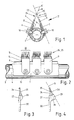
- FIG. 1 and 2 show a movement shaft 2 as it extends across the machine width in weft-knitting machines and can be rotated back and forth.
- a flat surface 4 is milled on both sides of the movement shaft over its length.
- the two surfaces 4 make an angle of e.g. 45 ° on.
- three supports 8, 9, each with a group of six perforated needles 12, are screwed on both sides. In most cases, significantly more carriers are arranged next to each other. Each of them can have more than six, e.g. B. contain eighteen needles.
- 5 and 5 ⁇ are two group planes that extend along the needles 12 through the heads 22 of both needle groups and intersect in the area of the heads.
- One hexagon socket screw 10 is screwed through a hole in each of the supports 8, 9 and the intermediate plates 6, 7 into a threaded bore in the movement shaft 2.
- the carriers 8, 9 each have a stop bar 14, which is located on the upper edge of the associated intermediate plate in FIG 6, 7 supports and serves to prevent rotation.
- the two carriers 8, 9 with their perforated needles 12 together form a segment which works together with a group of knitting needles in the machine.
- Each carrier 8, 9 is a cast body made of metal, in particular light metal or plastic, which holds the stems of the perforated needles 12 at the same mutual spacing with mutually parallel needle planes and aligned holes 20.
- the heads of the perforated needles provided with the holes are considerably thinner than the shafts, so that there is sufficient space between every two heads into which a head of a second group of needles can be inserted and also sufficient space for those through the holes 20 guided warp threads.
- FIG. 1 shows that the holes 20 of the heads of both needle groups are aligned. This is the ideal state, but it does not have to be achieved for an effective function. It is sufficient that the heads overlap one another, while the holes 20 of both needle groups can be slightly offset from one another.
- FIG. 3 shows another embodiment in which two needle groups 24 and 25 are anchored in a carrier 27 and 28, but both carriers are seated on a common circuit board 30.
- the two needle groups enclose a substantially smaller angle here than in FIG. 1.
- the angle can e.g. B. be 11 °.
- both carriers 24, 25 can be injection molded as a common block.
- the carriers 24, 25 can be injection-molded individually and, if made of metal, can be soldered to one another. If the supports are made of plastic, they can be welded together and, if the necessary durability can be achieved, can also be glued together.
- Segments according to Figure 3 are also attached to a motion shaft in the machine, but only on one side.
- FIG. 4 shows a further embodiment with three carriers 27, 28, 29 for three needle groups 24, 25, 26.
- the carriers are combined with one another in one of the ways described above. All three carriers sit on a common circuit board 30.
- the heads of the needle groups 24, 25, 26, 24, 25, etc. follow one another.
Landscapes
- Engineering & Computer Science (AREA)
- Textile Engineering (AREA)
- Knitting Machines (AREA)
- Organic Low-Molecular-Weight Compounds And Preparation Thereof (AREA)
Applications Claiming Priority (2)
| Application Number | Priority Date | Filing Date | Title |
|---|---|---|---|
| DE3637328 | 1986-11-03 | ||
| DE19863637328 DE3637328A1 (de) | 1986-11-03 | 1986-11-03 | Halterung dicht benachbarter lochnadeln |
Publications (1)
| Publication Number | Publication Date |
|---|---|
| EP0266481A1 true EP0266481A1 (fr) | 1988-05-11 |
Family
ID=6313012
Family Applications (1)
| Application Number | Title | Priority Date | Filing Date |
|---|---|---|---|
| EP87105107A Withdrawn EP0266481A1 (fr) | 1986-11-03 | 1987-04-07 | Dispositif de fixation pour des aiguilles à passettes juxtaposés et proches |
Country Status (11)
| Country | Link |
|---|---|
| US (1) | US4745781A (fr) |
| EP (1) | EP0266481A1 (fr) |
| AU (1) | AU8174187A (fr) |
| BR (1) | BR8702591A (fr) |
| CA (1) | CA1289763C (fr) |
| DD (1) | DD256533A5 (fr) |
| DE (1) | DE3637328A1 (fr) |
| PL (1) | PL268559A1 (fr) |
| PT (1) | PT86042A (fr) |
| WO (1) | WO1988003578A1 (fr) |
| ZA (1) | ZA874055B (fr) |
Cited By (4)
| Publication number | Priority date | Publication date | Assignee | Title |
|---|---|---|---|---|
| WO1994011554A1 (fr) * | 1992-11-12 | 1994-05-26 | Berger Gmbh, Treuchtlingen | Dispositif place sur un metier chaine pour crocheter une bande elastique recouverte d'un tissu duveteux et eventuellement pour crocheter des picos: bande elastique ainsi realisee |
| WO1995000690A1 (fr) * | 1993-06-24 | 1995-01-05 | Berger Gmbh | Dispositif de serrage et de guidage d'aiguilles a crocheter dans une machine a crocheter |
| EP1988198A1 (fr) * | 2007-05-03 | 2008-11-05 | Groz-Beckert KG | Ensemble d'outils et barre pour machine à tricoter de type chaîne |
| CN109072509A (zh) * | 2016-05-04 | 2018-12-21 | 格罗兹-贝克特公司 | 纺织工具模块和具有纺织工具模块的纺织机 |
Families Citing this family (2)
| Publication number | Priority date | Publication date | Assignee | Title |
|---|---|---|---|---|
| DE3840531C1 (de) * | 1988-12-01 | 1990-05-10 | Mayer Textilmaschf | Kettenwirkmaschine mit mindestens einer Barre |
| CN110586943A (zh) * | 2019-07-24 | 2019-12-20 | 嘉善日茸精密工业有限公司 | 经编机槽针的制作方法 |
Citations (3)
| Publication number | Priority date | Publication date | Assignee | Title |
|---|---|---|---|---|
| GB191204915A (en) * | 1912-02-27 | 1912-08-08 | Robert Baeumler | Improvements in Double Rib Warp Knitting Machines. |
| US3044283A (en) * | 1959-01-17 | 1962-07-17 | Wirkmaschinen Fabrik Wilhelm B | Warp knitting machines |
| GB951459A (en) * | 1960-07-08 | 1964-03-04 | Stanley Dolinsky | Improvements in warp knitting thread guide assembly |
Family Cites Families (5)
| Publication number | Priority date | Publication date | Assignee | Title |
|---|---|---|---|---|
| US2293123A (en) * | 1941-07-22 | 1942-08-18 | Celanese Corp | Guide |
| US3099921A (en) * | 1960-02-18 | 1963-08-06 | Liebrandt Karl | Warp knitting machine |
| DE1585148B1 (de) * | 1962-11-28 | 1970-07-23 | Karl Liebrandt | Befestigung der Fadenfuehrer von flachen Kettenwirkmaschinen |
| GB1085643A (en) * | 1964-03-13 | 1967-10-04 | Ici Ltd | Improvements in or relating to warp knitting |
| CH641853A5 (de) * | 1979-07-04 | 1984-03-15 | Textilma Ag | Maschine fuer die herstellung von maschenwaren und verfahren zum betrieb der maschine. |
-
1986
- 1986-11-03 DE DE19863637328 patent/DE3637328A1/de not_active Withdrawn
-
1987
- 1987-04-07 EP EP87105107A patent/EP0266481A1/fr not_active Withdrawn
- 1987-05-13 DD DD87302728A patent/DD256533A5/de not_active IP Right Cessation
- 1987-05-20 BR BR8702591A patent/BR8702591A/pt active Search and Examination
- 1987-06-05 ZA ZA874055A patent/ZA874055B/xx unknown
- 1987-06-26 US US07/066,713 patent/US4745781A/en not_active Expired - Fee Related
- 1987-06-29 CA CA000540832A patent/CA1289763C/fr not_active Expired - Lifetime
- 1987-10-21 AU AU81741/87A patent/AU8174187A/en not_active Abandoned
- 1987-10-21 WO PCT/EP1987/000619 patent/WO1988003578A1/fr not_active Ceased
- 1987-10-30 PT PT86042A patent/PT86042A/pt not_active Application Discontinuation
- 1987-11-02 PL PL26855987A patent/PL268559A1/xx unknown
Patent Citations (3)
| Publication number | Priority date | Publication date | Assignee | Title |
|---|---|---|---|---|
| GB191204915A (en) * | 1912-02-27 | 1912-08-08 | Robert Baeumler | Improvements in Double Rib Warp Knitting Machines. |
| US3044283A (en) * | 1959-01-17 | 1962-07-17 | Wirkmaschinen Fabrik Wilhelm B | Warp knitting machines |
| GB951459A (en) * | 1960-07-08 | 1964-03-04 | Stanley Dolinsky | Improvements in warp knitting thread guide assembly |
Cited By (7)
| Publication number | Priority date | Publication date | Assignee | Title |
|---|---|---|---|---|
| WO1994011554A1 (fr) * | 1992-11-12 | 1994-05-26 | Berger Gmbh, Treuchtlingen | Dispositif place sur un metier chaine pour crocheter une bande elastique recouverte d'un tissu duveteux et eventuellement pour crocheter des picos: bande elastique ainsi realisee |
| AU676224B2 (en) * | 1992-11-12 | 1997-03-06 | Berger Gmbh | Device on a warp knitting machine for crocheting an elastic band with a coating and possibly for crocheting picots, and an elastic band produced with this device |
| US5653127A (en) * | 1992-11-12 | 1997-08-05 | Berger Gmbh | Device on a warp knitting machine for crocheting an elastic band with fleece and an elastic band produced by this device |
| WO1995000690A1 (fr) * | 1993-06-24 | 1995-01-05 | Berger Gmbh | Dispositif de serrage et de guidage d'aiguilles a crocheter dans une machine a crocheter |
| EP1988198A1 (fr) * | 2007-05-03 | 2008-11-05 | Groz-Beckert KG | Ensemble d'outils et barre pour machine à tricoter de type chaîne |
| CN109072509A (zh) * | 2016-05-04 | 2018-12-21 | 格罗兹-贝克特公司 | 纺织工具模块和具有纺织工具模块的纺织机 |
| CN109072509B (zh) * | 2016-05-04 | 2021-05-18 | 格罗兹-贝克特公司 | 纺织工具模块和具有纺织工具模块的纺织机 |
Also Published As
| Publication number | Publication date |
|---|---|
| DD256533A5 (de) | 1988-05-11 |
| PL268559A1 (en) | 1988-09-29 |
| PT86042A (pt) | 1988-12-15 |
| AU8174187A (en) | 1988-06-01 |
| US4745781A (en) | 1988-05-24 |
| ZA874055B (en) | 1987-12-09 |
| WO1988003578A1 (fr) | 1988-05-19 |
| BR8702591A (pt) | 1988-06-14 |
| DE3637328A1 (de) | 1988-05-11 |
| CA1289763C (fr) | 1991-10-01 |
Similar Documents
| Publication | Publication Date | Title |
|---|---|---|
| DE4223642C2 (de) | Tufting-Maschine mit mindestens einer Barre und mehreren an die Barre nebeneinander ansetzbaren Moduln | |
| DE2828278C2 (de) | Nadelanordnung für eine Tuftingmaschine | |
| DE3805772C2 (de) | Vorrichtung zum Befestigen eines Nahtmaterials an einer chirurgischen Nähnadel | |
| EP0446215B1 (fr) | Module avec instruments de tufting | |
| DE4421388C2 (de) | Nadelbefestigungsvorrichtung für Wirkmaschinen | |
| EP1988198B1 (fr) | Ensemble d'outils et barre pour machine à tricoter de type chaîne | |
| DE2746725C2 (de) | Strickmaschinenschloß | |
| DE2544197C2 (de) | Aufnahmeplatte für die Schloßteile einer Strickmaschine | |
| DE2745793C3 (de) | Tufting-Maschine | |
| DE3637328A1 (de) | Halterung dicht benachbarter lochnadeln | |
| EP0366962A2 (fr) | Buse à fente | |
| DE2856344A1 (de) | Messeraggregat fuer eine tuftingmaschine | |
| DE19835500C1 (de) | Schneidvorrichtung zur Erzeugung einer Schlitzöffnung für ein Knopfloch | |
| DE4131809A1 (de) | Vorrichtung zum einspannen und fuehren von haekelnadeln fuer eine haekelmaschine | |
| DE2701881A1 (de) | Nadelstange fuer eine tuftingmaschine oder eine aehnliche maschine | |
| EP0123914A1 (fr) | Outil de tricotage étampé pour métier à tricoter | |
| DE2856342A1 (de) | Messeraggregat fuer eine tuftingmaschine | |
| DE4019111C2 (fr) | ||
| EP0244656A1 (fr) | Dispositif de serrage pour des aiguilles | |
| DE3241153C2 (de) | Einschließ- und Abschlagplatine für Wirk- oder Strickmaschinen | |
| EP3762172B1 (fr) | Buse de brasage et installation de brasage | |
| DE3019139C2 (de) | Haltevorrichtung für Tuftwerkzeuge sowie Werkzeug dafür | |
| DE8629269U1 (de) | Halterung dicht benachbarter Lochnadeln | |
| DE2713886C2 (de) | Vorrichtung zum Führen der Druckernadeln in einem Mosaiknadeldruckwerk | |
| DE102019119288A1 (de) | Stanzwerkzeug mit Bearbeitungsmodul, Anschlagklammer und Verbindungsklammer |
Legal Events
| Date | Code | Title | Description |
|---|---|---|---|
| PUAI | Public reference made under article 153(3) epc to a published international application that has entered the european phase |
Free format text: ORIGINAL CODE: 0009012 |
|
| AK | Designated contracting states |
Kind code of ref document: A1 Designated state(s): AT BE CH DE ES FR GB GR IT LI LU NL SE |
|
| 17P | Request for examination filed |
Effective date: 19880521 |
|
| 17Q | First examination report despatched |
Effective date: 19900111 |
|
| STAA | Information on the status of an ep patent application or granted ep patent |
Free format text: STATUS: THE APPLICATION IS DEEMED TO BE WITHDRAWN |
|
| 18D | Application deemed to be withdrawn |
Effective date: 19900724 |
|
| RIN1 | Information on inventor provided before grant (corrected) |
Inventor name: BERGER, JOHANN Inventor name: BERGER, JOSEF Inventor name: SCHUELEIN, FRITZ |