EP0266539A2 - Oberflächeninterferometer - Google Patents
Oberflächeninterferometer Download PDFInfo
- Publication number
- EP0266539A2 EP0266539A2 EP87114049A EP87114049A EP0266539A2 EP 0266539 A2 EP0266539 A2 EP 0266539A2 EP 87114049 A EP87114049 A EP 87114049A EP 87114049 A EP87114049 A EP 87114049A EP 0266539 A2 EP0266539 A2 EP 0266539A2
- Authority
- EP
- European Patent Office
- Prior art keywords
- light
- beams
- parallel
- interferometer
- location
- Prior art date
- Legal status (The legal status is an assumption and is not a legal conclusion. Google has not performed a legal analysis and makes no representation as to the accuracy of the status listed.)
- Granted
Links
Images
Classifications
-
- G—PHYSICS
- G01—MEASURING; TESTING
- G01B—MEASURING LENGTH, THICKNESS OR SIMILAR LINEAR DIMENSIONS; MEASURING ANGLES; MEASURING AREAS; MEASURING IRREGULARITIES OF SURFACES OR CONTOURS
- G01B11/00—Measuring arrangements characterised by the use of optical techniques
- G01B11/16—Measuring arrangements characterised by the use of optical techniques for measuring the deformation in a solid, e.g. optical strain gauge
- G01B11/161—Measuring arrangements characterised by the use of optical techniques for measuring the deformation in a solid, e.g. optical strain gauge by interferometric means
-
- G—PHYSICS
- G01—MEASURING; TESTING
- G01B—MEASURING LENGTH, THICKNESS OR SIMILAR LINEAR DIMENSIONS; MEASURING ANGLES; MEASURING AREAS; MEASURING IRREGULARITIES OF SURFACES OR CONTOURS
- G01B9/00—Measuring instruments characterised by the use of optical techniques
- G01B9/02—Interferometers
- G01B9/02015—Interferometers characterised by the beam path configuration
- G01B9/02017—Interferometers characterised by the beam path configuration with multiple interactions between the target object and light beams, e.g. beam reflections occurring from different locations
- G01B9/02019—Interferometers characterised by the beam path configuration with multiple interactions between the target object and light beams, e.g. beam reflections occurring from different locations contacting different points on same face of object
-
- G—PHYSICS
- G01—MEASURING; TESTING
- G01B—MEASURING LENGTH, THICKNESS OR SIMILAR LINEAR DIMENSIONS; MEASURING ANGLES; MEASURING AREAS; MEASURING IRREGULARITIES OF SURFACES OR CONTOURS
- G01B9/00—Measuring instruments characterised by the use of optical techniques
- G01B9/02—Interferometers
- G01B9/02015—Interferometers characterised by the beam path configuration
- G01B9/02027—Two or more interferometric channels or interferometers
- G01B9/02028—Two or more reference or object arms in one interferometer
-
- G—PHYSICS
- G01—MEASURING; TESTING
- G01B—MEASURING LENGTH, THICKNESS OR SIMILAR LINEAR DIMENSIONS; MEASURING ANGLES; MEASURING AREAS; MEASURING IRREGULARITIES OF SURFACES OR CONTOURS
- G01B9/00—Measuring instruments characterised by the use of optical techniques
- G01B9/02—Interferometers
- G01B9/02097—Self-interferometers
Definitions
- the technical field of the invention is in the use of optical information from different optical path lengths to provide information on the condition of the surface of an object.
- interferometer type apparatus to measure small dimensions has been employed in the art.
- One type of these devices has come to be known as a dilatometer.
- Such devices generally employ reflective members that change length and/or direction of a plurality of light beams emanating from a common source, so that dimensional information can be correlated with frequency shifts in the beams in relation to each other.
- a dilatometer is shown in U.S. Patent 3,788,746 wherein the corners of a prism are used together with reflections from the front and back surfaces of the prism.
- Sensitivity is another desirable feature. Sensitivity has been achieved by angular adjustment of the components. Such a structure is illustrated in a device known as Jamin's interferometer described in Optical Interferometer, by M. Francone, (Academic Press, 1966), page 99. This device employs a light path that is reflected from both the front and the back surfaces of two relatively parallel angularly mounted reflecting mirrors. The sensitivity is achieved by angular adjustment that moves the mirrors out of parallel.
- the invention is an interferometer for indicating surface conditions of a workpiece.
- a beam of coherent light is split into three parallel beams by reflection from the front and back surfaces of a parallel faced reflecting member, the three parallel beams are then reflected from the surface of a workpiece and the three parallel beams reflected from the workpiece are combined by reflection from the front and back surfaces of a parallel faced reflecting member finally being directed to a separate sensor for each beam.
- the condition of the surface such as reflectivity, displacement, rotation and bending, is measured by phase difference between the center and each of the outer beams.
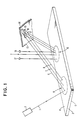
- a beam of coherent light 1 is supplied from a light source 2, such as a laser.
- the beam 1 strikes a parallel reflecting surface member 3.
- the parallel reflecting surface member 3 has a front reflecting surface 4 and a parallel back reflecting surface 5.
- the light is split into three parallel beams 6, 7 and 8 by reflection from one or both of the two reflecting surfaces 4 and 5 at a first or splitting location 9.
- the three parallel beams 6, 7 and 8 then strike adjacent regions 10, 11 and 12 of the surface 13 of a workpiece 14.
- the surface 13 at the center region 11 has an object 15 thereon having a surface that is displaced from the surface at regions 10 and 12, such as would be the condition with a conductive member on a semiconductor wafer.
- the three parallel beams after reflection from regions 10, 11 and 12 are further reflected at a second or combining location 16 to sensors 17 and 18.
- the invention structure is advantageous in diagnostics and as a manufacturing tool. Its structural simplicity provides usefulness under conditions of stress. It is further relatively insensitive to vibration noise and to uniform motion in both the lateral and longitudinal directions of the workpiece surface. There is sufficient sensitivity that 1 milliwatt of light energy and a 1 Angstrom protrusion can be measured. With such sensitivity, the region around the parts can be affected by such environmental influences as air currents so that shielding would be employed where high sensitivity is desired.
- the parallel reflecting surface member 3 may be an ordinary mirror. Enhanced sensitivity is achieved by providing partial reflectivity of surface 3 and higher reflectivity at surface 5.
- the sensors 17 and 18 may be any semiconductor photodiode.
- the coherent light 1 is divided or split into parallel beams using reflections from both surfaces at one location and after being reflected from a workpiece surface the beams are combined at another location using internal reflections from both surfaces to permit surface differences to be translated into optical phase differences.
- the difference in optical path length between the beams 6 and 7 and 7 and 8 produced by such surface variations at the workpiece as displacement, reflectivity, bending and rotation is manifested through the combination of the beams by internal reflection from the two parallel surfaces 4 and 5 to provide intensity variations at the sensors 17 and 18 due to constructive and destructive light beam interference.
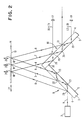
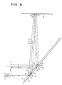
- the internal light beam interference in the combining location 16 is illustrated in detail in connection with different structural arrangements in FIGS. 2 and 6.
- FIG. 2 a structural arrangement is provided in which the parallel reflecting surface element 3 is constructed so that the splitting location 9 and the combining location 16 are arranged by divergent source 1 and sensors 17 and 18 positioning.
- This structural arrange ment provides inter-element dimensional flexibility.
- the divergent positioning is achieved by making the element 3 of two pieces.
- light 1 from the source 2 strikes the member 3 at the splitting location 9.
- a portion of the light 1 strikes the front reflecting surface 4 at a location 20.
- the reflected beam from location 20 is labelled 6.
- the light 1 also continues to the back reflecting surface 5 where it is reflected at location 21.
- the reflected beam from location 21 is labelled 7 and is parallel to beam 6.
- a portion of the light reflected at location 21 is reflected from the internal side of the front reflecting surface 4 at location 22 to location 23 at the rear reflecting surface 5 where, upon again being reflected, forms a beam 8 that is parallel to both beams 6 and 7.
- the coherent light source 1 has thus been split into three parallel beams 6, 7 and 8 and each strikes a separate location 10, 11 and 12, respectively, on the surface 13 of the workpiece 14.
- the parallel beams 6, 7 and 8 are reflected still in parallel from the surface 13 of the workpiece 14 at locations 10, 11 and 12. Any variation orthogonal to surface 13 as shown by arrows 24, 25 and 26 of locations 10, 11 and 12 with respect to other locations will change the optical path length relationship of the center beam 7 with respect to either or both outer beams 6 and 8.
- the invention is insensitive to a variation, as illustrated by arrow 27 in a direction essentially parallel to the surface 13 inasmuch as surface 13 is truly planar since the relative optical path lengths are not affected. It is also insensitive to uniform motion of workpiece 14 parallel to the beams 6, 7 and 8.
- the member 3 is changed in direction at 33 using two orthogonal pieces.
- the internal reflections between the parallel faces 4 and 5 operate to provide either constructive or destructive interference between the center beam 7 and either or both of the outer beams 6 and 8.
- the beam is reflected from the back surface 5 at location 28 to sensor 17.
- Beam 7 strikes front surface 4 at location 29 where one portion proceeds through member 3 to location 30 where it is reflected from surface 5 to exit from the member 3 and another portion is reflected at location 29 where it constructively or destructively combines with beam 6.
- Beam 8 enters member 3 at location 31 and is reflected from surface 5 at location 32 to sensor 18. A portion of the light from beam 7 is reflected at the internal surface of 4 at location 31 to combine with beam 8 to provide a constructive or destructive interference with beam 7. The points of combination are shown as curved arrows.
- the sensors 17 and 18 detect the phase difference between beams 6 and 7 and 7 and 8, respectively, through the intensity resulting from the interference between each outer beam and the center.
- the phase difference producing the interference is the result of the path length difference between the beams.
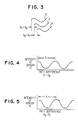
- FIGS. 3, 4 and 5 the sensing of the intensity resulting from the interference is schematically illustrated.
- the phase relationship is illustrated for illustrative different path length situation.
- the phase offset due to the different path lengths causes the intensity as sensed by a sensor 17 for beams 6 and 7 and 18 for beams 7 and 8 to increase or decrease as the interference is constructive or destructive so that the intensity at the sensor follows the oscillating curves of FIGS. 4 and 5 with a period equal to the optical wavelength ⁇ .
- the change in intensity is indicative of displacement, and can be resolved into rotation and bending modes of the workpiece.
- the sensor may be a simple photovoltaic device which provides a voltage corresponding to light intensity which in turn is usable in the standard practice in the art to indicate the surface conditions under study, such as setting acceptability limits as is standard in the art.
- element 15 in FIG. 1 can be viewed as a bending type surface variation in that locations 10 and 12 are farther away than location 11 whereas were there to be another displacement element similar to 15 positioned at either location 10 or 12, a rotation type surface variation would be indicated.
- FIG. 6 a preferred embodiment is provided in which the parallel reflecting surface member 3 is straight with the splitting location 9 and the combining location 16 merely separated.
- FIGS. 1, 2 and 6 the same reference numerals are employed.
- the parallel reflecting surface member 3 may be a simple mirror.
- the structure provides further flexibility in location of individual components.
- the source 2 of coherent light 1 may be any monochromatic optical source with low beam divergence.
- a helium neon laser with a wavelength ( ⁇ ) of 6328 ⁇ is ideally adapted for this purpose.
- the parallel reflecting surface member 3 in splitting and combining can be any mirror with plane parallel surfaces. There is some enhancement in sensitivity if surface 4 is partially reflecting and surface 5 totally reflecting. The surfaces 4 and 5 are separated by about 3 millimeters.
- the distance from the locations 9 and 16 to the surface 13 is of the order of 50 to 200 millimeters.
- the distance between surface locations 10, 11 and 12 is of the order of 5 millimeters between each location.
- the detectors 17 and 18 are silicon photodiodes.
- the measurements of rotation, where the optical paths to the two external locations 10 and 12 are such that one is shorter and one is longer than the optical path to location 11, and the measurement of bending, where the optical path to one location, such as 11, is shorter than the optical path to either or both of the other locations 10 and 12 is performed by a simultaneous detection of the phase shifts at 17 and 18, in accordance with the following table.
- the structure has the advantages that the interfering beams all reflect from different points on the same optical elements which in turn greatly reduces the susceptibility to vibrations.
- Transverse alignment is dependent only on the splitting and combining locations having parallel surfaces. Thus, a change of mirrors requires no realignment.
- a displacement interferometer wherein a coherent light beam is reflected from both sides of an ordinary mirror at a splitting location producing three parallel beams which beams in turn are reflected from separate locations on a workpiece back to a combining location where they are directed to two separate sensors. Any difference in displacement of the locations on the surface of the workpiece produces an optical phase shift which may be instrumented to indicate an intensity variation observation so that each sensor provides a measure of the relative displacement of adjacent points on the workpiece.
Landscapes
- Physics & Mathematics (AREA)
- General Physics & Mathematics (AREA)
- Length Measuring Devices By Optical Means (AREA)
- Instruments For Measurement Of Length By Optical Means (AREA)
Applications Claiming Priority (2)
| Application Number | Priority Date | Filing Date | Title |
|---|---|---|---|
| US92849686A | 1986-11-07 | 1986-11-07 | |
| US928496 | 1986-11-07 |
Publications (3)
| Publication Number | Publication Date |
|---|---|
| EP0266539A2 true EP0266539A2 (de) | 1988-05-11 |
| EP0266539A3 EP0266539A3 (de) | 1991-08-07 |
| EP0266539B1 EP0266539B1 (de) | 1993-06-16 |
Family
ID=25456316
Family Applications (1)
| Application Number | Title | Priority Date | Filing Date |
|---|---|---|---|
| EP19870114049 Expired - Lifetime EP0266539B1 (de) | 1986-11-07 | 1987-09-25 | Oberflächeninterferometer |
Country Status (3)
| Country | Link |
|---|---|
| EP (1) | EP0266539B1 (de) |
| JP (1) | JPS63124901A (de) |
| DE (1) | DE3786227T2 (de) |
Cited By (3)
| Publication number | Priority date | Publication date | Assignee | Title |
|---|---|---|---|---|
| GB2516277A (en) * | 2013-07-17 | 2015-01-21 | Cambridge Consultants | Optical apparatus and methods |
| GB2516281A (en) * | 2013-07-17 | 2015-01-21 | Cambridge Consultants | Optical apparatus and methods |
| WO2015008074A1 (en) * | 2013-07-17 | 2015-01-22 | Cambridge Consultants Limited | Optical apparatus and methods |
Family Cites Families (5)
| Publication number | Priority date | Publication date | Assignee | Title |
|---|---|---|---|---|
| US3832063A (en) * | 1972-02-01 | 1974-08-27 | Canon Kk | Lens axis detection using an interferometer |
| US3788746A (en) * | 1972-10-02 | 1974-01-29 | Hewlett Packard Co | Optical dilatometer |
| JPS567006A (en) * | 1979-06-22 | 1981-01-24 | Ibm | Method of extending measurement range of interference |
| SE435966B (sv) * | 1982-02-02 | 1984-10-29 | Asea Ab | Fiberoptiskt metdon |
| US4512661A (en) * | 1982-09-02 | 1985-04-23 | The United States Of America As Represented By The Aministration Of The National Aeronautics And Space Administration | Dual differential interferometer |
-
1987
- 1987-09-18 JP JP62232753A patent/JPS63124901A/ja active Pending
- 1987-09-25 DE DE19873786227 patent/DE3786227T2/de not_active Expired - Fee Related
- 1987-09-25 EP EP19870114049 patent/EP0266539B1/de not_active Expired - Lifetime
Cited By (3)
| Publication number | Priority date | Publication date | Assignee | Title |
|---|---|---|---|---|
| GB2516277A (en) * | 2013-07-17 | 2015-01-21 | Cambridge Consultants | Optical apparatus and methods |
| GB2516281A (en) * | 2013-07-17 | 2015-01-21 | Cambridge Consultants | Optical apparatus and methods |
| WO2015008074A1 (en) * | 2013-07-17 | 2015-01-22 | Cambridge Consultants Limited | Optical apparatus and methods |
Also Published As
| Publication number | Publication date |
|---|---|
| JPS63124901A (ja) | 1988-05-28 |
| EP0266539A3 (de) | 1991-08-07 |
| DE3786227D1 (de) | 1993-07-22 |
| EP0266539B1 (de) | 1993-06-16 |
| DE3786227T2 (de) | 1993-12-02 |
Similar Documents
| Publication | Publication Date | Title |
|---|---|---|
| US4962669A (en) | Method and apparatus for measuring deformations of test samples in a testing machine | |
| EP0250306A2 (de) | Interferometer zur Winkelmessung | |
| JPH03223609A (ja) | タッチプローブ | |
| US4571083A (en) | Standing wave interferometer for measuring optical path differences | |
| US4504147A (en) | Angular alignment sensor | |
| US4729654A (en) | Laser interferometer | |
| KR950021326A (ko) | 반도체 웨이퍼의 절연막 두께를 측정하기 위한 방법 및 장치 | |
| US4836031A (en) | Method and apparatus for measuring deformations of test samples in testing machines | |
| EP0266539B1 (de) | Oberflächeninterferometer | |
| US5011287A (en) | Interferometer object position measuring system and device | |
| US5187545A (en) | Integrated optical position measuring device and method with reference and measurement signals | |
| US6433350B2 (en) | Multi-range fiber-optic reflective displacement micrometer | |
| US5002371A (en) | Low coupling beam splitter and laser power or position monitor using same | |
| JPH07190712A (ja) | 干渉計 | |
| JP4334380B2 (ja) | 形状測定装置 | |
| EP0553826B1 (de) | Detektoranordnung | |
| JPH03226614A (ja) | 試験機において試験片あるいは被試験体の変形を測定する方法とその装置 | |
| JPS6355035B2 (de) | ||
| KR100332035B1 (ko) | 단일 파장 레이저 광의 다중패스를 이용한 거리 측정장치 및 방법 | |
| JP2592254B2 (ja) | 変位量及び変位速度の測定装置 | |
| JPH044966Y2 (de) | ||
| JPH0754802Y2 (ja) | 接触式表面形状測定器 | |
| JPH09196619A (ja) | 微小変位量の測定方法及び装置 | |
| JPH0454405A (ja) | 光学式変位計 | |
| JP3955400B2 (ja) | 寸法測定装置 |
Legal Events
| Date | Code | Title | Description |
|---|---|---|---|
| PUAI | Public reference made under article 153(3) epc to a published international application that has entered the european phase |
Free format text: ORIGINAL CODE: 0009012 |
|
| AK | Designated contracting states |
Kind code of ref document: A2 Designated state(s): DE FR GB IT |
|
| 17P | Request for examination filed |
Effective date: 19880910 |
|
| PUAL | Search report despatched |
Free format text: ORIGINAL CODE: 0009013 |
|
| AK | Designated contracting states |
Kind code of ref document: A3 Designated state(s): DE FR GB IT |
|
| 17Q | First examination report despatched |
Effective date: 19911212 |
|
| GRAA | (expected) grant |
Free format text: ORIGINAL CODE: 0009210 |
|
| AK | Designated contracting states |
Kind code of ref document: B1 Designated state(s): DE FR GB IT |
|
| PG25 | Lapsed in a contracting state [announced via postgrant information from national office to epo] |
Ref country code: IT Free format text: LAPSE BECAUSE OF FAILURE TO SUBMIT A TRANSLATION OF THE DESCRIPTION OR TO PAY THE FEE WITHIN THE PRE;WARNING: LAPSES OF ITALIAN PATENTS WITH EFFECTIVE DATE BEFORE 2007 MAY HAVE OCCURRED AT ANY TIME BEFORE 2007. THE CORRECT EFFECTIVE DATE MAY BE DIFFERENT FROM THE ONE RECORDED.SCRIBED TIME-LIMIT Effective date: 19930616 |
|
| REF | Corresponds to: |
Ref document number: 3786227 Country of ref document: DE Date of ref document: 19930722 |
|
| ET | Fr: translation filed | ||
| PLBE | No opposition filed within time limit |
Free format text: ORIGINAL CODE: 0009261 |
|
| STAA | Information on the status of an ep patent application or granted ep patent |
Free format text: STATUS: NO OPPOSITION FILED WITHIN TIME LIMIT |
|
| 26N | No opposition filed | ||
| PGFP | Annual fee paid to national office [announced via postgrant information from national office to epo] |
Ref country code: GB Payment date: 19960827 Year of fee payment: 10 |
|
| PGFP | Annual fee paid to national office [announced via postgrant information from national office to epo] |
Ref country code: FR Payment date: 19960909 Year of fee payment: 10 |
|
| PGFP | Annual fee paid to national office [announced via postgrant information from national office to epo] |
Ref country code: DE Payment date: 19960917 Year of fee payment: 10 |
|
| PG25 | Lapsed in a contracting state [announced via postgrant information from national office to epo] |
Ref country code: GB Free format text: LAPSE BECAUSE OF NON-PAYMENT OF DUE FEES Effective date: 19970925 |
|
| PG25 | Lapsed in a contracting state [announced via postgrant information from national office to epo] |
Ref country code: FR Free format text: THE PATENT HAS BEEN ANNULLED BY A DECISION OF A NATIONAL AUTHORITY Effective date: 19970930 |
|
| GBPC | Gb: european patent ceased through non-payment of renewal fee |
Effective date: 19970925 |
|
| PG25 | Lapsed in a contracting state [announced via postgrant information from national office to epo] |
Ref country code: DE Free format text: LAPSE BECAUSE OF NON-PAYMENT OF DUE FEES Effective date: 19980603 |
|
| REG | Reference to a national code |
Ref country code: FR Ref legal event code: ST |