EP0266582B1 - Meule pour bois - Google Patents
Meule pour bois Download PDFInfo
- Publication number
- EP0266582B1 EP0266582B1 EP87114887A EP87114887A EP0266582B1 EP 0266582 B1 EP0266582 B1 EP 0266582B1 EP 87114887 A EP87114887 A EP 87114887A EP 87114887 A EP87114887 A EP 87114887A EP 0266582 B1 EP0266582 B1 EP 0266582B1
- Authority
- EP
- European Patent Office
- Prior art keywords
- auxiliary
- ram
- press
- grindstone
- wood pulp
- Prior art date
- Legal status (The legal status is an assumption and is not a legal conclusion. Google has not performed a legal analysis and makes no representation as to the accuracy of the status listed.)
- Expired - Lifetime
Links
- 239000002023 wood Substances 0.000 title claims abstract description 29
- 229920001131 Pulp (paper) Polymers 0.000 claims abstract 14
- 238000010276 construction Methods 0.000 claims description 4
- 238000006073 displacement reaction Methods 0.000 claims 3
- 239000004575 stone Substances 0.000 description 10
- 238000010009 beating Methods 0.000 description 9
- 238000000227 grinding Methods 0.000 description 5
- RRLHMJHRFMHVNM-BQVXCWBNSA-N [(2s,3r,6r)-6-[5-[5-hydroxy-3-(4-hydroxyphenyl)-4-oxochromen-7-yl]oxypentoxy]-2-methyl-3,6-dihydro-2h-pyran-3-yl] acetate Chemical group C1=C[C@@H](OC(C)=O)[C@H](C)O[C@H]1OCCCCCOC1=CC(O)=C2C(=O)C(C=3C=CC(O)=CC=3)=COC2=C1 RRLHMJHRFMHVNM-BQVXCWBNSA-N 0.000 description 4
- 238000000034 method Methods 0.000 description 2
- 230000006835 compression Effects 0.000 description 1
- 238000007906 compression Methods 0.000 description 1
- 239000000463 material Substances 0.000 description 1
- 238000003801 milling Methods 0.000 description 1
- 238000005192 partition Methods 0.000 description 1
Images
Classifications
-
- D—TEXTILES; PAPER
- D21—PAPER-MAKING; PRODUCTION OF CELLULOSE
- D21B—FIBROUS RAW MATERIALS OR THEIR MECHANICAL TREATMENT
- D21B1/00—Fibrous raw materials or their mechanical treatment
- D21B1/04—Fibrous raw materials or their mechanical treatment by dividing raw materials into small particles, e.g. fibres
- D21B1/12—Fibrous raw materials or their mechanical treatment by dividing raw materials into small particles, e.g. fibres by wet methods, by the use of steam
- D21B1/14—Disintegrating in mills
- D21B1/18—Disintegrating in mills in magazine-type machines
- D21B1/24—Disintegrating in mills in magazine-type machines of the pocket type
Definitions
- the invention relates to a wood grinder according to the preamble of claim 1.
- a wood grinder is known from German patent specification 297 810.
- press rams which are each guided in press chambers, which also serve as loading chambers for the wood beating around them to feed the common grinder magazine.
- press rams are alternately pressurized so that due to the pressure propagation in the wood pile forming a pile in the press magazine, the pressing pressure propagates from wood beating to wood beating up to the grindstone surface.
- the ram for the loading process is withdrawn into the upper pressure position, and after the other ram has dropped during its working stroke, the working stroke of this ram, which is associated with the just loaded partial magazine, is initiated. It is advisable to load each of the partial magazines of the individual press rams parallel to the axial direction of the grinder stone, since otherwise it would not be possible to load the partial magazines properly.
- the distance of the lower edge, close to the grinder stone, of the central wall of the press magazines, which is arranged between them, i.e. also the lower stroke end of the press ram is of course to be chosen so that the grinding pressure exerted by a ram can also spread over the entire width of the press magazine in the area of the grinder stone surface in accordance with the slope angle for the pressure profile.
- a disadvantage of this arrangement is that both the sub-magazines assigned to the individual rams must each be loaded with the wood beating themselves, so that a separate loading device is necessary in each case. Furthermore, in order to ensure the full pressing pressure and its uniformity with each working thrust, end plates must be provided in the area of the part magazine assigned to each individual pressing ram in the area near the grindstone, although these are not mentioned in the patent specification.
- the object of the invention is now to provide a wood grinder in which only a single loading device for the press magazines is necessary.
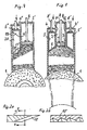
- Fig. 1 is in the middle of the magazine arrangement and the grindstone 1, the main press chamber 2, in which the main press ram 3 is arranged, which can be moved via push rod 8.
- the drive of the ram is omitted. They are generally designed as known hydraulic servomotors.
- To the side of the main press chamber 2 are the auxiliary press chambers 4 and 4 'with the associated auxiliary press dies 5 and 5', which are similarly driven by push rods 8 '.
- the inner chamber walls 11, 12, which are parts of the main press chamber 2 simultaneously form the inner walls of the secondary press chambers 4 and 4 '.
- the length - i.e. in axial, i.e. Stroke direction measured - the secondary press ram is preferably approximately equal to their effective press stroke, generally their stroke at all.
- the position of the secondary ram 5 and 5 'shown is their starting position before the press stroke, at least as far as it concerns the beginning of the pressing of the wood by this ram.
- the main press ram 3 is withdrawn without the pressure in the drive from the wood beating changes.
- an end plate 7 is preferably pushed under the main press die 3 before it is retracted, so that the wood beating is prevented from escaping upwards.
- the main press chamber 2 is reloaded with the wood beating, the end plate is pulled out of the press magazine again and the working stroke of the main press ram 3 begins.
- the lower surface that is to say the bottom surface 6 or 17 of the secondary press rams is inclined, essentially parallel to the tangent to the grindstone surface in the area where the projection in the direction of the push rods of the secondary press rams falls on the grindstone surface.
- This inclination can also be chosen somewhat differently, since it serves to generate the greatest possible force component in the direction of the grinder stone axis or the uppermost point of the grinder stone surface. This is to ensure that the pressure across the entire grinding zone affects the pile of wood beating as evenly as possible.
- the end plate should be pushed in under the working pressure of the main press die 3 as far as possible, its edge in the closing pressure is sharpened, preferably with a long inclined surface, which is provided with file-like or rasp-like teeth, around the surface of the wooden stick over which the end plate slides to mill off and thus reduce the resistance for pushing in the end plate.
- the chips and the escaping wood moisture on the milling surfaces lead to reduced frictional resistance.
- the contact pressure of the press rams could also be temporarily removed or reduced.
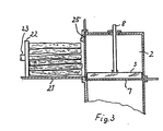
- FIG. 3 the press grinder is shown in cross section in the area of the main press die 3 seen from the side.
- a wooden feed floor 21 is provided, which belongs to a wooden feed chamber which is open at the top, on which the wooden bumps are stored with their longitudinal extension parallel to the axis of the grinder stone 1 in order to be moved into the main press chamber 2 by means of a press ram 22 - actuated by a piston rod 23 . After this process, this is shut off by the lateral slide 25, which must also be sealed pressure-tight in the event that an excess pressure is to be maintained in the grinder housing.
- Fig. 4 a variant is shown in which there is only a secondary press chamber 4 "and a secondary press ram 5".
- the bottom surface 17 'of the secondary press ram 5 " is rounded off on its side facing the main press chamber 2 with a large radius which is in the range 4/5 of the width of the secondary press chamber 4" - measured in the circumferential direction of the grinder stone - or is somewhat larger. This ensures that when the secondary press ram 5 "is raised, the wood pushed in by the main press ram 3 or 3 'can be better distributed in the wide magazine and there is no sudden, lateral evasion of individual wood prods. Thus, the wood prods gradually slide to the side of the declining secondary press stamp.
- the embodiment according to FIG. 4 seems to offer advantages over the one according to FIG. 1 in this respect.
- the drive mechanism for the secondary press ram is also lighter here, since only a single secondary ram has to be driven.
- the secondary press ram can be designed as a laterally open hollow box construction. It can be stiffened inside the box by means of ribs 19 and 20.
- the length of the secondary press punches 5, 5 ', 5 " is preferably at least half the total stroke of the same, but at least equal to half the effective working stroke.
- the length of the secondary press punches is preferably at least 4/5 of the effective working stroke of the same.
- the length of the secondary press punches will also be at least 80% of the total stroke of the same, in order to avoid excessive switching frequency. In order to save material, it is better to choose the hollow construction according to FIG. 1 or the box construction according to FIG. 4 of the secondary press punches.
- Fig. 1 is indicated by the dash-dotted lines yet another embodiment of the wooden shaft, in which the side walls have an inclination between 5 and 10 ° to each other, by the narrowing of the shaft a more uniform and stronger pressure of the wooden billets on the grinder stone by Ensure ram.
- the wooden shaft would have to be made relatively long, since the side shaft walls must be parallel in the stroke area of the secondary punches 5 and 5 '.
- the wide part of the wooden shaft could then be made relatively wide in order to obtain the same length of the grinding zone in its narrow part adjacent to the grinding stone surface as would be present without the inclined shaft walls.
Landscapes
- Engineering & Computer Science (AREA)
- Life Sciences & Earth Sciences (AREA)
- Wood Science & Technology (AREA)
- Mechanical Engineering (AREA)
- Chemical And Physical Treatments For Wood And The Like (AREA)
- Debarking, Splitting, And Disintegration Of Timber (AREA)
- Oscillators With Electromechanical Resonators (AREA)
- Diaphragms For Electromechanical Transducers (AREA)
- Paper (AREA)
- Grinding Of Cylindrical And Plane Surfaces (AREA)
Claims (13)
Priority Applications (1)
| Application Number | Priority Date | Filing Date | Title |
|---|---|---|---|
| AT87114887T ATE56764T1 (de) | 1986-10-24 | 1987-10-13 | Holzschleifer. |
Applications Claiming Priority (2)
| Application Number | Priority Date | Filing Date | Title |
|---|---|---|---|
| DE3636226 | 1986-10-24 | ||
| DE19863636226 DE3636226A1 (de) | 1986-10-24 | 1986-10-24 | Holzschleifer |
Publications (2)
| Publication Number | Publication Date |
|---|---|
| EP0266582A1 EP0266582A1 (fr) | 1988-05-11 |
| EP0266582B1 true EP0266582B1 (fr) | 1990-09-19 |
Family
ID=6312401
Family Applications (1)
| Application Number | Title | Priority Date | Filing Date |
|---|---|---|---|
| EP87114887A Expired - Lifetime EP0266582B1 (fr) | 1986-10-24 | 1987-10-13 | Meule pour bois |
Country Status (7)
| Country | Link |
|---|---|
| US (1) | US4840317A (fr) |
| EP (1) | EP0266582B1 (fr) |
| AT (1) | ATE56764T1 (fr) |
| DE (2) | DE3636226A1 (fr) |
| ES (1) | ES2017487B3 (fr) |
| FI (1) | FI83792C (fr) |
| NO (1) | NO874424L (fr) |
Families Citing this family (3)
| Publication number | Priority date | Publication date | Assignee | Title |
|---|---|---|---|---|
| FI101895B (fi) * | 1996-12-16 | 1998-09-15 | Valmet Corp | Sovitelma puiden syöttämiseksi puuhiomakoneessa |
| FI101894B1 (fi) * | 1996-12-16 | 1998-09-15 | Valmet Corp | Sovitelma jatkuvatoimisen hionnan aikaansaamiseksi puuhiomakoneessa |
| AT410762B (de) * | 2001-01-15 | 2003-07-25 | Bacher Helmut | Vorrichtung zur zerkleinerung von abfallgut, insbesondere kunststoffabfällen, und verfahren zu ihrem betrieb |
Family Cites Families (6)
| Publication number | Priority date | Publication date | Assignee | Title |
|---|---|---|---|---|
| DE297810C (fr) * | ||||
| US1359016A (en) * | 1919-11-15 | 1920-11-16 | James H Baker | Pulp-wood grinder |
| DE421188C (de) * | 1924-05-09 | 1925-11-07 | Amme Fa | Holzschleifer mit gruppenweise vereinigten Presskaesten |
| DE548889C (de) * | 1928-04-01 | 1932-04-21 | J M Voith Fa | Holzschleifer mit Vorrichtung zum Anpressen des Holzes in breiten Presskaesten |
| DE814096C (de) * | 1948-10-02 | 1951-09-20 | Voith Gmbh J M | Verfahren und Vorrichtung zum Betrieb von Holzschleifern |
| FI69653C (fi) * | 1984-01-09 | 1986-03-10 | Tampella Oy Ab | Foerfarande och matningsanordning foer inmatning av en vedsatsi en tryckslipmaskin |
-
1986
- 1986-10-24 DE DE19863636226 patent/DE3636226A1/de not_active Withdrawn
-
1987
- 1987-10-13 DE DE8787114887T patent/DE3765083D1/de not_active Expired - Fee Related
- 1987-10-13 EP EP87114887A patent/EP0266582B1/fr not_active Expired - Lifetime
- 1987-10-13 ES ES87114887T patent/ES2017487B3/es not_active Expired - Lifetime
- 1987-10-13 AT AT87114887T patent/ATE56764T1/de not_active IP Right Cessation
- 1987-10-22 US US07/112,252 patent/US4840317A/en not_active Expired - Fee Related
- 1987-10-23 FI FI874682A patent/FI83792C/fi not_active IP Right Cessation
- 1987-10-23 NO NO874424A patent/NO874424L/no unknown
Also Published As
| Publication number | Publication date |
|---|---|
| DE3636226A1 (de) | 1988-04-28 |
| EP0266582A1 (fr) | 1988-05-11 |
| FI83792C (fi) | 1991-08-26 |
| DE3765083D1 (de) | 1990-10-25 |
| ATE56764T1 (de) | 1990-10-15 |
| ES2017487B3 (es) | 1991-02-16 |
| NO874424D0 (no) | 1987-10-23 |
| FI874682L (fi) | 1988-04-25 |
| NO874424L (no) | 1988-04-25 |
| US4840317A (en) | 1989-06-20 |
| FI83792B (fi) | 1991-05-15 |
| FI874682A0 (fi) | 1987-10-23 |
Similar Documents
| Publication | Publication Date | Title |
|---|---|---|
| DE2536044A1 (de) | Schrottpresse | |
| DE2728203A1 (de) | Ballenpresse mit einem mehrere schnuernuten aufweisenden presstempel | |
| EP0266582B1 (fr) | Meule pour bois | |
| DE102018133264A1 (de) | Paketierpresse und Verfahren zum Paketieren von verformbarem Material | |
| DE2810070A1 (de) | Schliessvorrichtung fuer fuellstationen von strangpressen | |
| DE3321844C2 (fr) | ||
| DE3441405C2 (fr) | ||
| EP0048383B1 (fr) | Presse pour fabriquer des balles ligaturées de matériaux de déchets | |
| AT360457B (de) | Maschine zum herstellen von gleichen teig- teilchen | |
| DD269825A5 (de) | Extrusionskopf mit einer klemmeinrichtung fuer die werkzeugteile | |
| DE1627837C3 (de) | Presse, insbesondere Strangpresse | |
| DE102012021153C5 (de) | Kanalballenpresse mit optimiertem Ausweichraum | |
| DE3120897A1 (de) | "presse zum herstellen von holmen oder platten aus verleimten staeben" | |
| DE3906107A1 (de) | Quadratische presse | |
| DE2811376C3 (de) | Rotor für Prallmühlen, insbesondere für Sandprallmühlen | |
| DE3202748A1 (de) | Vorrichtung zum verdichten von fleisch, speck u.dgl. | |
| DE3143690C2 (fr) | ||
| DE3624867A1 (de) | Vorrichtung zum diskontinuierlichen ausschleusen von material | |
| DE2703327C3 (de) | Formgebungsvorrichtung für Banderolen für eine Tiefziehmaschine zur Herstellung thermoplastischer Behälter | |
| DE10106094B4 (de) | Ballenpresse | |
| DE1627825B2 (de) | Presse zum anbringen von metallverbindungsplatten an holzbinderteilen | |
| DE69714073T2 (de) | Beschickungsvorrichtung in einem holzschleifer | |
| EP4013607B1 (fr) | Presse à balles et procédé de mise en balle de matériau déformable | |
| AT371312B (de) | Verfahren und vorrichtung zur herstellung von teigstuecken | |
| EP3551445B1 (fr) | Tête de pressage, dispositif de pressage d'un produit à presser et procédé de pressage d'un produit à presser |
Legal Events
| Date | Code | Title | Description |
|---|---|---|---|
| PUAI | Public reference made under article 153(3) epc to a published international application that has entered the european phase |
Free format text: ORIGINAL CODE: 0009012 |
|
| AK | Designated contracting states |
Kind code of ref document: A1 Designated state(s): AT BE DE ES IT SE |
|
| 17P | Request for examination filed |
Effective date: 19880521 |
|
| 17Q | First examination report despatched |
Effective date: 19891208 |
|
| GRAA | (expected) grant |
Free format text: ORIGINAL CODE: 0009210 |
|
| AK | Designated contracting states |
Kind code of ref document: B1 Designated state(s): AT BE DE ES IT SE |
|
| REF | Corresponds to: |
Ref document number: 56764 Country of ref document: AT Date of ref document: 19901015 Kind code of ref document: T |
|
| REF | Corresponds to: |
Ref document number: 3765083 Country of ref document: DE Date of ref document: 19901025 |
|
| ITF | It: translation for a ep patent filed | ||
| PLBE | No opposition filed within time limit |
Free format text: ORIGINAL CODE: 0009261 |
|
| STAA | Information on the status of an ep patent application or granted ep patent |
Free format text: STATUS: NO OPPOSITION FILED WITHIN TIME LIMIT |
|
| 26N | No opposition filed | ||
| PGFP | Annual fee paid to national office [announced via postgrant information from national office to epo] |
Ref country code: BE Payment date: 19911008 Year of fee payment: 5 |
|
| PGFP | Annual fee paid to national office [announced via postgrant information from national office to epo] |
Ref country code: AT Payment date: 19911010 Year of fee payment: 5 |
|
| PGFP | Annual fee paid to national office [announced via postgrant information from national office to epo] |
Ref country code: SE Payment date: 19911011 Year of fee payment: 5 |
|
| PGFP | Annual fee paid to national office [announced via postgrant information from national office to epo] |
Ref country code: ES Payment date: 19911015 Year of fee payment: 5 |
|
| ITTA | It: last paid annual fee | ||
| PGFP | Annual fee paid to national office [announced via postgrant information from national office to epo] |
Ref country code: DE Payment date: 19911111 Year of fee payment: 5 |
|
| PG25 | Lapsed in a contracting state [announced via postgrant information from national office to epo] |
Ref country code: AT Effective date: 19921013 |
|
| PG25 | Lapsed in a contracting state [announced via postgrant information from national office to epo] |
Ref country code: SE Effective date: 19921014 Ref country code: ES Free format text: LAPSE BECAUSE OF THE APPLICANT RENOUNCES Effective date: 19921014 |
|
| PG25 | Lapsed in a contracting state [announced via postgrant information from national office to epo] |
Ref country code: BE Effective date: 19921031 |
|
| BERE | Be: lapsed |
Owner name: J.M. VOITH G.M.B.H. Effective date: 19921031 |
|
| PG25 | Lapsed in a contracting state [announced via postgrant information from national office to epo] |
Ref country code: DE Effective date: 19930701 |
|
| EUG | Se: european patent has lapsed |
Ref document number: 87114887.0 Effective date: 19930510 |
|
| REG | Reference to a national code |
Ref country code: ES Ref legal event code: FD2A Effective date: 19991102 |
|
| PG25 | Lapsed in a contracting state [announced via postgrant information from national office to epo] |
Ref country code: IT Free format text: LAPSE BECAUSE OF NON-PAYMENT OF DUE FEES;WARNING: LAPSES OF ITALIAN PATENTS WITH EFFECTIVE DATE BEFORE 2007 MAY HAVE OCCURRED AT ANY TIME BEFORE 2007. THE CORRECT EFFECTIVE DATE MAY BE DIFFERENT FROM THE ONE RECORDED. Effective date: 20051013 |