EP0266629A2 - Appareil pour effectuer l'ouverture automatique et le mélange de balles de fibres - Google Patents
Appareil pour effectuer l'ouverture automatique et le mélange de balles de fibres Download PDFInfo
- Publication number
- EP0266629A2 EP0266629A2 EP87115389A EP87115389A EP0266629A2 EP 0266629 A2 EP0266629 A2 EP 0266629A2 EP 87115389 A EP87115389 A EP 87115389A EP 87115389 A EP87115389 A EP 87115389A EP 0266629 A2 EP0266629 A2 EP 0266629A2
- Authority
- EP
- European Patent Office
- Prior art keywords
- machine frame
- removal roller
- carriage
- removal
- side walls
- Prior art date
- Legal status (The legal status is an assumption and is not a legal conclusion. Google has not performed a legal analysis and makes no representation as to the accuracy of the status listed.)
- Withdrawn
Links
Images



Classifications
-
- B—PERFORMING OPERATIONS; TRANSPORTING
- B08—CLEANING
- B08B—CLEANING IN GENERAL; PREVENTION OF FOULING IN GENERAL
- B08B15/00—Preventing escape of dirt or fumes from the area where they are produced; Collecting or removing dirt or fumes from that area
- B08B15/002—Preventing escape of dirt or fumes from the area where they are produced; Collecting or removing dirt or fumes from that area using a central suction system, e.g. for collecting exhaust gases in workshops
- B08B15/005—Preventing escape of dirt or fumes from the area where they are produced; Collecting or removing dirt or fumes from that area using a central suction system, e.g. for collecting exhaust gases in workshops comprising a stationary main duct with one or more branch units, the branch units being freely movable along a sealed longitudinal slit in the main duct
-
- D—TEXTILES; PAPER
- D01—NATURAL OR MAN-MADE THREADS OR FIBRES; SPINNING
- D01G—PRELIMINARY TREATMENT OF FIBRES, e.g. FOR SPINNING
- D01G13/00—Mixing, e.g. blending, fibres; Mixing non-fibrous materials with fibres
-
- D—TEXTILES; PAPER
- D01—NATURAL OR MAN-MADE THREADS OR FIBRES; SPINNING
- D01G—PRELIMINARY TREATMENT OF FIBRES, e.g. FOR SPINNING
- D01G7/00—Breaking or opening fibre bales
- D01G7/04—Breaking or opening fibre bales by means of toothed members
Definitions
- the invention relates to a device for the automatic opening and mixing of fiber bales with a removal device which is suspended from a bale part of a portal-like machine frame which can be moved along a rail guide and which can be lowered onto the bale, and to a conveyor device assigned to the removal device.
- the bales should be set up as easily as possible in a confined space without placing the bales on special tables or similar support means.
- the removal device should be able to be installed in any intended factory hall without taking any special measures and should take up little space.
- Devices for the automatic opening and mixing of fiber bales are known (DE-OS 3.208.346), which have a tower-like machine frame, on which the removal device is attached on one side as a delivery arm. They are in this machine frame entire driving and lifting equipment including the removal device for the opened fiber material.
- this machine frame takes up a large amount of space in relation to the working width of the take-off device, which is lost for the installation of bales. In order to use this lost space, it is mostly used for the pneumatic or mechanical removal of the opened fiber material. With such a conveyor belt or a transport channel, the bale footprint is also not accessible from this side.
- the one part of the machine frame that supports the bridge part contains the conveying and drive means and a weighing device.
- the fiber material is conveyed transversely to the direction of travel of the machine frame to this weighing device, in which a fiber mixture is put together by weight and from which the weighted amount is thrown onto a conveyor belt installed along the path of the machine frame. All these devices have in common that they are extremely complex and also hinder the accessibility and installation of the bales to a great extent. The space requirement in relation to the working width is large.
- the object of the present invention is to provide a device of the type mentioned at the outset, which is simple in its structure and makes good use of the available space while avoiding these disadvantages.
- the removal device is a removal roller, the axis of rotation of which is arranged transversely to the direction of movement of the machine frame and whose working width is at least 75% of the total width of the machine frame.
- the bridge part connects two side walls to one another, which are provided with impellers and are arranged at a distance corresponding to one another at least two bale widths.
- the wall thickness of the side walls is 30%, preferably 20%, of the working width of the removal roller, since they essentially serve only as a support and as a chassis. All space-consuming devices are arranged in the bridge part and in the area of the bridge part.
- the removal roller is expediently mounted on a carriage that can be raised and lowered.
- the movement of the carriage in the vertical direction is made possible by the fact that the carriage is suspended at both ends on chain-like drive transmission elements which are guided over a common drive shaft.
- the movement of the carriage in a defined plane is achieved in that the carriage is guided in the side walls by means of straight guides.
- the measure that the wheels of the machine frame are driven synchronously via chains or toothed belts ensures the trouble-free travel of the device.
- the drive transmission elements are arranged in the side walls of the machine frame. To save space, they are Drive motors for the carriage and the wheels arranged in the bridge part. A torsion of the driven shafts is compensated for in that the drive motors transmit the drive approximately centrally between the side walls to the shafts.
- a limitation of the amount of fiber taken off by the removal roller is achieved in that hold-down rollers are arranged on the slide parallel to the removal roller and in the vicinity thereof.
- the hold-down roller is preferably driven at the driving speed of the machine frame.
- the drive motors for the rotation of the removal roller and the hold-down rollers are mounted on the slide.
- the stripping roller is assigned an effective, rake-like stripping element over its working width, which is arranged behind the stripping roller in the direction of rotation, excess fiber quantities are stripped from the stripping roller and conveyed back onto the bale surface.
- the cover consists of at least one cover plate which is guided in the side walls and can be moved up and down by the slide in the manner of a blind.
- two overlapping cover plates are provided as a cover, which are space-saving in the bridge part when the slide is raised.
- a suction channel above the bale is used as the conveying device for the fiber material accepted by the bale is stationary. This means that the bale footprint is easily accessible from all sides.
- a uniform suction of the removed fiber material over the working width of the removal roller is achieved in that the suction channel is connected via pipes to two suction openings in a suction hood covering the removal roller.
- the suction of the fiber material in the outer edge areas is ensured by the fact that the suction openings are each arranged near the ends of the removal roller. So that the pipes can follow the vertical movement of the removal roller and the suction hood, they are at least partially designed as an expandable bellows.
- the connection of the pipes to the suction channel is preferably carried out in such a way that the pipes open into movable, opposing connection openings which are part of a longitudinal slot in the suction channel which can be closed by a cover band.
- the movable connection openings are expediently located on a carriage which is coupled to the machine frame via fork-like carriers.
- the travel distance of the machine frame can preferably be determined by a pulse counting device which is arranged on the suction channel. This protects the pulse counter from damage.
- the bale removal device shown in FIGS. 1 and 2 contains a machine frame with two narrow side walls 1 and 2, which are connected to one another by a bridge part 3.
- the side walls 1 and 2 are attached to a chassis 4 provided with wheels 41 and 42 or are integrated into this.
- the wheels 41 and 42 guided in rails 40 are driven synchronously.
- they are connected to a drive shaft 46 via chain wheels 4S and 44 and chain drives 45 which engage in these and are arranged in the side walls 1 and 2.
- the latter is driven by a motor 47, which is arranged in the bridge part 3, via a gear transmission 48.
- the motor 47 and the drive shaft 46 like all drive means mentioned later, are arranged above the bales B to be processed in order to save space.
- the side walls 1 and 2 are at a distance from one another which corresponds to at least two bale widths.
- cotton bales B of rectangular shape are processed and arranged for this purpose in series on the floor between the side walls 1 and 2 in such a way that their abutting longitudinal sides lie essentially parallel to the rails 40.
- a spacing of the side walls 1 and 2 from one another is preferably provided, which makes it possible to arrange five fiber bales B next to one another, as shown in FIG. 1.
- the working width of the removal roller 6 is at least 75% of the total width of the machine frame and the wall thickness of the side walls 1 and 2 is 30%, but preferably 20% of the working width of the removal roller 6.
- the removal roller 6 and two hold-down rollers 7 and 70 are mounted in a carriage 52, which is suspended at its two ends on chains 5 or chain-like elements and can slide up and down in vertical guides (not shown) provided in the side walls 1 and 2.
- the hold-down rollers 7 and 70 equipped with toothed disks are arranged in the direction of travel of the device directly in front of and behind the removal roller 6 and parallel to it. Furthermore, a suction hood 8 covering the removal roller 6 is fastened to the carriage 52.
- the chains 5, on which the carriage 52 is suspended, and the drive chains 45 for the machine frame are in the side walls 1 and 2 for reasons of space and safety arranged.
- the chains 5 are each guided via a stationary chain wheel 54 near the ground and a chain wheel 56 seated on a drive shaft 5 lying above the bale B.
- a motor 57 arranged in the bridge part 3 drives the drive shaft 55 via a gear transmission 58, as a result of which the carriage 52 and thus the removal roller 6 with the hold-down rollers 7 and 70 assigned to it and the suction hood 8 are moved in the vertical direction.
- a motor 61 mounted on the carriage 52 rotates the removal roller 6, which essentially extends from wall to wall, via a belt drive 62.
- the hold-down rollers 7 and 70 are driven in rotation by a motor 71 mounted on the carriage 52 at the driving speed of the machine frame.
- a toothed belt 72 is used as the drive transmission means.
- the hold-down rollers 7 and 70 have the same direction of rotation as the removal roller 6 (FIG. 6).
- the two drive motors 47 and 57 are arranged in the bridge part 3 approximately centrally between the side walls 1 and 2. This compensates for torsion of the shafts 46 and 55.
- the area between the bridge part 3 and the carriage 52 is closed by a cover 32 shown in FIG. 3, which prevents fiber fly and dust from escaping into the open.
- the cover 32 is formed by two smooth sheets 33 and 34, which extend over the working width of the removal roller 6 and can slide in vertical guides in the side walls 1 and 2.
- the lower plate 33 lies on a bracket of the carriage 52.
- the guides for the upper plate 34 are offset from the guides for the lower plate 33 and extend so far down that the plates 33 and 33 overlap even when the carriage 52 is completely lowered.
- the sheets 33 and 34 are made of Carriage 52 moving in the vertical direction is carried along and moved up and down in the manner of a blind, so that the area between the carriage 52 and the bridge part 3 remains closed in every position of the carriage 52.
- the cover 32 can also be formed by a single sheet.
- the suction hood 8 has two suction openings 81 and 82, which are preferably each arranged in the vicinity of the ends of the removal roller 6 and are connected via pipes 83 and 84 to a suction channel 9 arranged above the bales B.
- the pipelines 83 and 84 are designed as extendable bellows, at least in some areas. This allows you to follow an up and down movement of the removal device without the risk of jamming, as is the case with a telescopic tube. In this way, misalignments can also be compensated for.
- the arrangement of the suction channel 9 shown approximately in the center above the bale B is preferred for fluidic and space reasons. However, an arrangement to the side of the bale, possibly also at a low height, is not excluded.
- the suction channel 9 extends in the direction of the bale row over its entire length and has a longitudinal slot 91 facing the bale B, which is closed by a cover band 92 (FIG. 2).
- the cover band 92 consists of spring steel and is held in the closed position by magnetic action.
- a carriage 93 suspended on the suction duct 9 carries deflection rollers 94, 95 and at a distance from these further deflection rollers 96, 97, over which the cover band 92 is guided such that it leaves opposite connection openings 98 into which the two pipes 83 and 84 open .
- the car 93 is coupled to the bridge part 3 via fork-like drivers 31 which are fastened to the latter and is displaced by the latter along the suction channel 9 when the removal device starts to move.
- a pulse counter 49 is also arranged (FIGS. 4 and 5), by means of which the travel distance of the machine frame is determined.
- the pulses are triggered by notches 99, which are provided at equal intervals on a flange of the suction channel 9.
- the pulse counting device is firmly connected to the bridge part 3 by means of a holder and is thus displaced along the notches 99 when the removal device is moved.
- the device is driven at a predetermined driving speed in the direction of the arrow (FIGS. 2 and 6) by the motor 47 via the chain drives 45, the removal roller 6, previously lowered to the bale surface together with the hold-down rollers 7 and 70, taking fiber material from the bale and throws against the direction of travel to the suction hood 8.
- the fiber material is gripped by the suction air flow and conveyed through the pipes 83 and 84 into the suction channel 9 for further removal. Since the fiber material is removed and sucked off by two, preferably five, fiber bales B, the fiber material is already mixed in connection with the fiber removal, which is caused by the suction air flow.
- the hold-down rollers 7 and 70 which press on the bale surface and are driven by the motor 71 at the driving speed of the machine frame, limit the amount of fiber material removed and neutralize a force component acting in the direction of decrease.
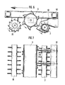
- the removal roller 6 can also be rake-like arranged scraper elements 63 (FIGS. 6 and 7) are assigned in order to convey back undissolved fiber material which has been carried along by the removal roller back onto the bale surface.
- the stripping elements 63 are fastened in the direction of rotation behind the removal roller 6 on the carriage 52, their tips being arranged at a predetermined, adjustable distance from the impact circle of the removal roller 6 or can also extend into the impact circle if the arrangement of the rows of teeth on the removal roller permits this.
- flanges 64 can be arranged at both ends of the removal roller 6, the diameter of which is slightly larger than the diameter of the tip circle of the teeth 65 fastened on the circumference of the removal roller 6 (FIGS. 8, 9).
- the flanged wheels 64 lie on the ground when processing the last fiber layer of the bales and ensure that the teeth 65 of the removal roller 6 rotate at a distance from the ground. Damage to teeth 65 is thereby avoided.
- such flanges are arranged on at least one of the hold-down rollers. 10 and 11, the hold-down roller 7 is provided with flanges 64.
- the flanges 64 in this case have a larger diameter than the tip circle of the teeth of the toothed disks 73.
- the side parts can be kept narrow. They essentially serve only as a support and as a chassis.
Landscapes
- Engineering & Computer Science (AREA)
- Textile Engineering (AREA)
- Preliminary Treatment Of Fibers (AREA)
Applications Claiming Priority (2)
| Application Number | Priority Date | Filing Date | Title |
|---|---|---|---|
| DE19863637578 DE3637578A1 (de) | 1986-11-04 | 1986-11-04 | Vorrichtung zum selbsttaetigen oeffnen und mischen von faserballen |
| DE3637578 | 1986-11-04 |
Publications (2)
| Publication Number | Publication Date |
|---|---|
| EP0266629A2 true EP0266629A2 (fr) | 1988-05-11 |
| EP0266629A3 EP0266629A3 (fr) | 1990-01-17 |
Family
ID=6313165
Family Applications (1)
| Application Number | Title | Priority Date | Filing Date |
|---|---|---|---|
| EP87115389A Withdrawn EP0266629A3 (fr) | 1986-11-04 | 1987-10-21 | Appareil pour effectuer l'ouverture automatique et le mélange de balles de fibres |
Country Status (6)
| Country | Link |
|---|---|
| US (1) | US4845812A (fr) |
| EP (1) | EP0266629A3 (fr) |
| JP (1) | JPS63126920A (fr) |
| CN (1) | CN1017731B (fr) |
| BR (1) | BR8705607A (fr) |
| DE (1) | DE3637578A1 (fr) |
Cited By (3)
| Publication number | Priority date | Publication date | Assignee | Title |
|---|---|---|---|---|
| US5117534A (en) * | 1989-12-19 | 1992-06-02 | Trutzschler Gmbh & Co. Kg | Method for detaching tufts from fiber bales |
| EP3564419A1 (fr) * | 2018-05-04 | 2019-11-06 | Trützschler GmbH & Co. KG | Ouvreuse de balles doté d'une unité d'enlèvement à changement de hauteur et son unité de freinage |
| WO2019211017A1 (fr) * | 2018-05-04 | 2019-11-07 | Trützschler GmbH & Co.KG | Brise-balles destiné à l'ouvraison de balles de fibres comprimées, doté d'un système de protection contre les collisions |
Families Citing this family (18)
| Publication number | Priority date | Publication date | Assignee | Title |
|---|---|---|---|---|
| DE3924807A1 (de) * | 1989-07-27 | 1991-01-31 | Truetzschler & Co | Vorrichtung zum oeffnen von faserballen aus baumwolle, chemiefasern u. dgl. mit einer abstuetzeinrichtung |
| DE4022680A1 (de) * | 1990-07-17 | 1992-01-23 | Hergeth Hubert A | Ballenabtragungsmaschine |
| DE4022679A1 (de) * | 1990-07-17 | 1992-01-23 | Hergeth Hubert A | Bahnfraese |
| RU2202661C1 (ru) * | 2002-01-31 | 2003-04-20 | Южно-Российский государственный университет экономики и сервиса | Способ отбора волокна с поверхности кип и устройство для его осуществления |
| CN103014928A (zh) * | 2012-12-27 | 2013-04-03 | 苏州弘贸纺织有限公司 | 一种轨道式压棉杆 |
| CH710258A1 (de) * | 2014-10-16 | 2016-04-29 | Rieter Ag Maschf | Ballenöffner. |
| CN105380327B (zh) * | 2015-12-07 | 2017-03-22 | 广东溢达纺织有限公司 | 自动拆领机及其自动拆领方法 |
| CH712367A1 (de) * | 2016-04-15 | 2017-10-31 | Rieter Ag Maschf | Verfahren zur Kalibrierung der Aufliegekraft eines Abtragorgans eines Ballenöffners und Ballenöffner. |
| CH712385A1 (de) * | 2016-04-22 | 2017-10-31 | Rieter Ag Maschf | Verfahren zur Längspositionsbestimmung und zur Längspositionierung eines Abtragorgans eines Ballenöffners und Ballenöffner. |
| CN106111414A (zh) * | 2016-08-23 | 2016-11-16 | 无锡溥汇机械科技有限公司 | 一种锂电池喷涂机吸雾装置 |
| CN106637525B (zh) * | 2017-03-03 | 2018-11-16 | 唐山市长亮纺织有限公司 | 一种具有限位圆盘的可调节抓棉小车架 |
| DE102017115161A1 (de) * | 2017-05-15 | 2018-11-15 | Temafa Maschinenfabrik Gmbh | Faserfördervorrichtung sowie Fasermischanlage |
| DE102018110671A1 (de) | 2018-05-04 | 2019-11-07 | TRüTZSCHLER GMBH & CO. KG | Ballenöffner zum Öffnen von gepressten Faserballen mit einem verbesserten Grundaufbau |
| DE102018110679A1 (de) | 2018-05-04 | 2019-11-07 | TRüTZSCHLER GMBH & CO. KG | Ballenöffner zum Öffnen von gepressten Faserballen |
| DE102018110677A1 (de) * | 2018-05-04 | 2019-11-07 | TRüTZSCHLER GMBH & CO. KG | Ballenöffner mit einem Maschinengestell in Portalbauweise und mit einer an dem Maschinengestell angeordneten Abnehmereinheit |
| DE102018110798A1 (de) | 2018-05-04 | 2019-11-07 | TRüTZSCHLER GMBH & CO. KG | Ballenöffner mit einer verbesserten Laufschiene zur Führung eines Maschinengestells |
| CN108796672B (zh) * | 2018-08-24 | 2023-09-08 | 安徽四惠电缆有限公司 | 一种清钢联多仓打手轴头自清洁装置 |
| CN114249116A (zh) * | 2020-09-21 | 2022-03-29 | 安徽日发纺织机械有限公司 | 一种往复抓棉机抓臂旋转装置 |
Family Cites Families (11)
| Publication number | Priority date | Publication date | Assignee | Title |
|---|---|---|---|---|
| US3663993A (en) * | 1971-02-22 | 1972-05-23 | Crompton & Knowles Corp | Apparatus for plucking a dense mass of fibers |
| IT1009799B (it) * | 1974-04-10 | 1976-12-20 | Marzoli E C Spa Flli | Metodo ed impianto di dosaggio per fibre tessili |
| DE2857520C2 (de) * | 1978-11-02 | 1982-02-18 | Trützschler GmbH & Co KG, 4050 Mönchengladbach | Vorrichtung zum Abstützen von Textilfaserballen an Ballenöffnern |
| DE2847460C3 (de) * | 1978-11-02 | 1981-10-08 | Trützschler GmbH & Co KG, 4050 Mönchengladbach | Verfahren zum Öffnen von mehreren Textilfaserballen |
| US4467502A (en) * | 1981-03-26 | 1984-08-28 | Fiber Controls Corporation | Fiber bale opener |
| DE3210602A1 (de) * | 1981-03-26 | 1982-10-07 | Fiber Controls Corp., 28052 Gastonia, N.C. | Verfahren und vorrichtung zum brechen von ballen aus textilfasern |
| DE3208346C2 (de) * | 1982-03-09 | 1984-11-29 | Hergeth GmbH & Co KG, 4408 Dülmen | Einrichtung zum Abtragen des Gutes von in Reihe aufgestellten Ballen aus Spinngut |
| US4507826A (en) * | 1982-10-13 | 1985-04-02 | Keller Alex J | Method and apparatus for opening fiber bales |
| US4610575A (en) * | 1984-07-05 | 1986-09-09 | Lummus Industries, Inc. | Apparatus for removing quantities of fiber from bales for blending purposes and the like |
| DE3503523C2 (de) * | 1985-02-02 | 1995-05-18 | Hergeth Hubert | Absaugvorrichtung für Ballenfräsen |
| DE3568596D1 (en) * | 1985-02-07 | 1989-04-13 | Rieter Ag Maschf | Method and control for a machine to strip off fibre flocks from textile fibre bales |
-
1986
- 1986-11-04 DE DE19863637578 patent/DE3637578A1/de not_active Withdrawn
-
1987
- 1987-10-20 BR BR8705607A patent/BR8705607A/pt unknown
- 1987-10-21 EP EP87115389A patent/EP0266629A3/fr not_active Withdrawn
- 1987-10-30 JP JP62273661A patent/JPS63126920A/ja active Pending
- 1987-11-02 US US07/115,752 patent/US4845812A/en not_active Expired - Fee Related
- 1987-11-03 CN CN87107667A patent/CN1017731B/zh not_active Expired
Cited By (3)
| Publication number | Priority date | Publication date | Assignee | Title |
|---|---|---|---|---|
| US5117534A (en) * | 1989-12-19 | 1992-06-02 | Trutzschler Gmbh & Co. Kg | Method for detaching tufts from fiber bales |
| EP3564419A1 (fr) * | 2018-05-04 | 2019-11-06 | Trützschler GmbH & Co. KG | Ouvreuse de balles doté d'une unité d'enlèvement à changement de hauteur et son unité de freinage |
| WO2019211017A1 (fr) * | 2018-05-04 | 2019-11-07 | Trützschler GmbH & Co.KG | Brise-balles destiné à l'ouvraison de balles de fibres comprimées, doté d'un système de protection contre les collisions |
Also Published As
| Publication number | Publication date |
|---|---|
| CN1017731B (zh) | 1992-08-05 |
| US4845812A (en) | 1989-07-11 |
| EP0266629A3 (fr) | 1990-01-17 |
| CN87107667A (zh) | 1988-06-22 |
| JPS63126920A (ja) | 1988-05-30 |
| DE3637578A1 (de) | 1988-05-11 |
| BR8705607A (pt) | 1988-06-14 |
Similar Documents
| Publication | Publication Date | Title |
|---|---|---|
| EP0266629A2 (fr) | Appareil pour effectuer l'ouverture automatique et le mélange de balles de fibres | |
| DE3637561C2 (fr) | ||
| CH667620A5 (de) | Verfahren und vorrichtung zum sammeln von gefalzten druckbogen. | |
| DE19605461A1 (de) | Vorrichtung zum Vereinzeln gestapelter flacher Werkstücke | |
| DE4105273A1 (de) | Vorrichtung zum stapeln von packungseinheiten | |
| EP0216057A1 (fr) | Semoir pneumatique monograine | |
| EP0311823A2 (fr) | Appareil pour ouvrir les balles de fibres | |
| DE2705236C2 (de) | Landwirtschaftliche Maschine mit einem Mähwerk | |
| EP0572861A1 (fr) | Dispositif pour séparer et transporter d'anneaux élastiques | |
| DE2819292B2 (de) | Vorrichtung zum Öffnen von Faserballen | |
| DE202022101368U1 (de) | Fahrzeugrad-Reinigungsvorrichtung | |
| DE2743602C3 (de) | Vorrichtung zur Entnahme von Silage aus einem Silo | |
| DE3637580C1 (de) | Vorrichtung zum Absaugen von Fasermaterial | |
| DE3232180A1 (de) | Ablaeng- und stapelvorrichtung fuer langgestrecktes gut | |
| EP0350749A2 (fr) | Dispositif pour l'enlèvement de feuilles d'une pile | |
| DE2828123A1 (de) | Vorrichtung zum ernten von beispielsweise rueben | |
| DE102022104849B3 (de) | Vorrichtung zur bewegten Warenpräsentation | |
| DE2416944A1 (de) | Vorrichtung zum oeffnen und mischen von faserballen | |
| DE3912564A1 (de) | Oeffnungsvorrichtung zum oeffnen von gepressten faserballen | |
| DE2647469B2 (de) | Antriebsanordnung für die Fräswalze an sog. Silofräsen | |
| EP1066127B1 (fr) | Dispositif de transport | |
| EP0293324A2 (fr) | Dispositif d'empilage | |
| DE2652618C2 (de) | Vorrichtung zum Umsetzen eines Schuppenstromes aus Papierbogen | |
| EP4454449A1 (fr) | Dispositif de placement de pommes de terre | |
| DE1919239C3 (de) | Schneidkopfsaugbagger |
Legal Events
| Date | Code | Title | Description |
|---|---|---|---|
| PUAI | Public reference made under article 153(3) epc to a published international application that has entered the european phase |
Free format text: ORIGINAL CODE: 0009012 |
|
| AK | Designated contracting states |
Kind code of ref document: A2 Designated state(s): CH DE FR GB IT LI |
|
| ITCL | It: translation for ep claims filed |
Representative=s name: ZINI MARANESI |
|
| GBC | Gb: translation of claims filed (gb section 78(7)/1977) | ||
| PUAL | Search report despatched |
Free format text: ORIGINAL CODE: 0009013 |
|
| EL | Fr: translation of claims filed | ||
| AK | Designated contracting states |
Kind code of ref document: A3 Designated state(s): CH DE FR GB IT LI |
|
| 17P | Request for examination filed |
Effective date: 19891218 |
|
| 17Q | First examination report despatched |
Effective date: 19910617 |
|
| STAA | Information on the status of an ep patent application or granted ep patent |
Free format text: STATUS: THE APPLICATION IS DEEMED TO BE WITHDRAWN |
|
| 18D | Application deemed to be withdrawn |
Effective date: 19920721 |
|
| RIN1 | Information on inventor provided before grant (corrected) |
Inventor name: DIE ANDERE ERFINDER HABEN AUF IHRE NENNUNG VERZICH Inventor name: LANDWEHRKAMP, HANS, DIPL.-ING. Inventor name: WALK, JOHANN, ING. GRAD. Inventor name: KRIECHBAUM, KURT, ING. GRAD. |