EP0266651A2 - Couverture pour bassins remplis de liquide - Google Patents
Couverture pour bassins remplis de liquide Download PDFInfo
- Publication number
- EP0266651A2 EP0266651A2 EP87115667A EP87115667A EP0266651A2 EP 0266651 A2 EP0266651 A2 EP 0266651A2 EP 87115667 A EP87115667 A EP 87115667A EP 87115667 A EP87115667 A EP 87115667A EP 0266651 A2 EP0266651 A2 EP 0266651A2
- Authority
- EP
- European Patent Office
- Prior art keywords
- plates
- floating
- dome
- cover according
- cover
- Prior art date
- Legal status (The legal status is an assumption and is not a legal conclusion. Google has not performed a legal analysis and makes no representation as to the accuracy of the status listed.)
- Withdrawn
Links
- 239000007788 liquid Substances 0.000 title claims abstract description 16
- 239000010865 sewage Substances 0.000 claims abstract description 4
- 230000008878 coupling Effects 0.000 claims description 18
- 238000010168 coupling process Methods 0.000 claims description 18
- 238000005859 coupling reaction Methods 0.000 claims description 18
- 239000011152 fibreglass Substances 0.000 claims description 5
- 239000002984 plastic foam Substances 0.000 claims description 2
- 230000002093 peripheral effect Effects 0.000 claims 1
- XLYOFNOQVPJJNP-UHFFFAOYSA-N water Substances O XLYOFNOQVPJJNP-UHFFFAOYSA-N 0.000 description 4
- 239000004033 plastic Substances 0.000 description 3
- 229920003023 plastic Polymers 0.000 description 3
- 238000004140 cleaning Methods 0.000 description 2
- 239000002131 composite material Substances 0.000 description 2
- 239000006260 foam Substances 0.000 description 2
- 239000000463 material Substances 0.000 description 2
- 238000000465 moulding Methods 0.000 description 2
- 230000002787 reinforcement Effects 0.000 description 2
- 239000005060 rubber Substances 0.000 description 2
- 125000006850 spacer group Chemical group 0.000 description 2
- 230000007704 transition Effects 0.000 description 2
- 238000011109 contamination Methods 0.000 description 1
- 238000005304 joining Methods 0.000 description 1
- 238000004519 manufacturing process Methods 0.000 description 1
- 239000000203 mixture Substances 0.000 description 1
- 230000000284 resting effect Effects 0.000 description 1
- 238000005096 rolling process Methods 0.000 description 1
- 230000009182 swimming Effects 0.000 description 1
- 229920003002 synthetic resin Polymers 0.000 description 1
- 239000000057 synthetic resin Substances 0.000 description 1
- 238000010257 thawing Methods 0.000 description 1
Images


Classifications
-
- B—PERFORMING OPERATIONS; TRANSPORTING
- B65—CONVEYING; PACKING; STORING; HANDLING THIN OR FILAMENTARY MATERIAL
- B65D—CONTAINERS FOR STORAGE OR TRANSPORT OF ARTICLES OR MATERIALS, e.g. BAGS, BARRELS, BOTTLES, BOXES, CANS, CARTONS, CRATES, DRUMS, JARS, TANKS, HOPPERS, FORWARDING CONTAINERS; ACCESSORIES, CLOSURES, OR FITTINGS THEREFOR; PACKAGING ELEMENTS; PACKAGES
- B65D88/00—Large containers
- B65D88/34—Large containers having floating covers, e.g. floating roofs or blankets
- B65D88/36—Large containers having floating covers, e.g. floating roofs or blankets with relatively movable sections
Definitions
- the invention relates to a cover for pools filled with liquid, in particular from sewage treatment plants, consisting of a plurality of cover elements which are at least partially supported by floats.
- a cover for liquid-filled basins is known, which is composed of individual domed cover plates with a ring sector-like base.
- the cover is supported on the one hand in the area of the pump sump on an annular float surrounding the pump sump and on the other hand on rollers on a rail ring fastened to the circular basin crown.
- Known covers of this type have the disadvantage that they are always matched precisely to the basin diameter or the base area of the basin. As soon as a larger basin is to be covered, the cover must be redesigned, the individual cover elements each having to be made according to the base area of the basin.
- the invention is therefore based on the object to provide a cover for liquid-filled pools, in particular from sewage treatment plants, which can be adapted in a simple manner and without great effort to different pool sizes and pool shapes without complex molding costs, which is easy to assemble without a crane and where the usual requirements for the highest snow loads can be largely neglected.
- the cover elements consist of floating plates and dome plates, which are arranged across the board and alternately to one another and are releasably connected to one another.
- This training gives the possibility of placing the individual, light and easily transportable floating plates at a distance from one another in the liquid in the pool and connecting them to one another through the dome plates - these are dome-shaped plates - so that there is a full coverage.
- the low weight of this cover is also due to the fact that no special measures have to be taken to support the snow load. If the snow load is high, the cover will submerge slightly for a short time, and the snow can be thawed by the liquid that has a higher temperature.
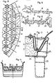
- the cover 1 shown only as a system in FIG. 1 consists of a plurality of floating plates 2, 3 and a plurality of coupling plates 4, which have the base of a regular hexagon or half a regular hexagon and are connected to one another in a manner that is not illustrated and explained further below.
- the floating plate 2 forms a so-called main float, around which dome plates 4 are connected at all six corners.
- Each floating plate 2 is made of glass fiber reinforced plastic as a relatively flat hollow body, which - as indicated in the present exemplary embodiment - is divided into six triangular hollow chambers. If necessary, the floating plate 2 can also be filled with foamed plastic (see FIG. 2).
- the floating plates 3 also consist of a hollow body made of glass fiber reinforced plastic, which, as indicated in FIG. 1, is divided into two chambers, for example, or, as can be seen in FIG. 3, is also filled with foam.
- a floating plate 5 is provided in the center between three floating plates 2 forming the corners of a triangle, which is formed either from six floating plates 3 or from three floating plates 2. If necessary, the floating plate 5 can also be formed in one piece. If necessary, two adjacent floating plates 3 can also be formed in one piece. It is advantageous to subdivide the floating plates 3, 5 into several smaller, if necessary, filled with synthetic resin foam chambers in order to ensure that, in the case of a leaky chamber, only an extremely small part of the floating plates 3, 5 impair the swimming function. The expansion of the chambers is min. 10 cm and max. about 40 cm.
- FIG. 1 of the drawing there are two lines 6 running parallel to each other over three coupling plates 4 arranged side by side. These lines 6 indicate that these three coupling plates 4 are either firmly connected to one another or are formed in one piece. It follows from this that a coupling element formed from three coupling plates 4 has three times the surface area as a floating plate 2. The same also applies to the floating plate 5.
- a cover 1 formed from floating plates 2, 3, 5 and dome plates 4 can be expanded to almost any size by adding individual floating plates 2, 3, 5 and dome plates 4 and thus adapted to the different sizes of the pools .
- 2 guide tubes 7 are inserted into the floating plates, which can accommodate support tubes, not shown, adjustable.
- each floating plate 5 can be provided with such guide tubes 7.
- Fig. 4 of the drawing the system of a cover 1a is shown, which is formed from cover elements with a triangular base.
- the base has an isosceles shape.
- the floating plates 3a have such a triangular base area and are provided in the drawing with a perpendicular bisector, which represents the subdivision of the floating plates 3a into two chambers, for example.
- the floating plates 2a have twice the base area as the floating plates 3a and have a Roman base area.
- the floating plates 2a, which are provided with a diagonal cross are preferably manufactured in one piece; however, they can also be composed of two floating plates 3a.
- the floating plates 2a, 3a are preferably formed from glass fiber reinforced plastic and are either hollow or filled with foamed plastic.
- the dome plates 4a also basically have the same base area as the floating plates 3a.
- several coupling plates 4a are combined to form a larger coupling plate.
- Dome plates 4a which are composed or formed in one piece are covered here either by two parallel lines 6 or by an elliptical line 8.
- 4 is now divided into four fields by dashed lines, in which different possible combinations or compositions of floating plates 2a, 3a and dome plates 4a are shown.
- Either four or six dome plates are combined to form a unit that forms either a Roman or a hexagonal base. Different covers 1a can be achieved by joining together such floating plates 2a and dome plates 4a.
- floating plates 2b with a square base are provided, which are connected to one another by dome plates 4b with a rectangular base.
- the dome plates 4b can have twice to five times the length of the floating plates 2b.
- the floating plates 2b of a row formed from floating plates 2b and dome plates 4b are arranged offset with respect to the floating plates 2b of the adjacent row.
- FIG. 6 shows the top view of a round basin 9, which can be supplemented with a corner 10 with a quadruple arrangement to form a square basin.
- the floating plates 2 basically have the area of a regular hexagon, while the dome plates 4 have the base of two hexagons and are therefore twice as large as the floating plates 2.
- the dome plates 4 change their direction in the individual sectors, which are characterized by floating plates 2 which are drawn more strongly. This alignment of the dome plates 4 thus results in six completely identical sectors, so that the edge connection of the cover 1, which will be discussed in more detail below, is reduced to six completely identical areas and can thus be considerably simplified.
- 7 now shows a floating plate 2 and a dome plate 4 formed from two hexagons, which thus has twice the base area as the floating plate 2.
- the floating plate 2 is provided with a circumferential projection 11 which in the exemplary embodiment shown has a trough-shaped cross section (FIG. 13).
- This groove-like projection 11 receives a correspondingly shaped side edge 12 of the dome plate 4.
- the dome plate 4 is made of two hexagonal domes 13 and has a sandwich-like reinforcement 14 in the transition area between the two domes 13, which is shaped like a staircase (FIGS. 8 and 9).
- FIG. 8 also shows in the right part that the side edges 15 of the coupling plate 4, to which a further coupling plate 4 is connected, have a sandwich-like reinforced flange 16 (FIG. 14).
- This step-like reinforcement 14 and the reinforced flange 16 give the possibility that there is a transition from each corner point of a floating plate 2 to the next floating plate 2. From Fig. 8 it can also be seen that the upper surface 17 of a floating plate 2 is convex. This design ensures that rainwater or the like can run to the edge of the floating plate 2 and thus into the channel-like projection 11.
- FIG. 10 shows the enlarged edge area of a sector of the cover 1 of FIG. 6.
- the edge area of such a cover 1 for a round basin is reduced to as few as possible closing parts 18 which can be connected to reduced coupling plates 4c or reduced floating plates 2c.
- the dome plates 4c (FIGS. 11 and 12) are provided with a bevel 19 which merges into a flange 16 or a side edge 12 in its lower region, as is the case with the normal dome plates 4.
- the end parts 18 are non-positively and / or positively connected to the coupling plates 4, 4c and the floating plates 2c. 11, the connecting part 18 consists of a relatively thin plate 20, which is reinforced by float 21 and is therefore designed to be walked on.
- the plate 20 is angled downward and immersed in the liquid in the basin as a so-called odor trap.
- the plate 20 of the connecting part 18 is designed as a sandwich composite element which either contains the additional floats 21 or is formed in one piece with the same.
- an angle piece 22 is connected here, which is also immersed as an odor trap in the liquid of the pool.
- a special edge profile 23 can be provided here, which protrudes above the pelvic crown and protects it from contamination or snow. This is important if the pelvic crown is used to hold a running rail for the drive wheels of a scraper bridge.
- FIG. 13 shows the edge of a floating plate 2 with a channel-like projection 11.
- several small spacers for example made of rubber, are placed on the bottom of the channel-like projection, on which then the side edge 12 of the dome plate 4 rests. This creates below the side edge 12 small channels 24, which allow, for example, the passage of rainwater or the like.
- the spacers made of rubber also ensure that no noise is generated, for example, when the wind is used.
- the side edges 12 of the dome plates 4 are held in their position in the channel-like projection 11 by means of a bracket 25.
- each floating plate 3 can, if necessary, be filled with water, for example rainwater, which only runs into the pool via the outer edge of the projection 11 when a predetermined liquid level is exceeded. This results in an optimal odor trap.
- the above-described connection between a floating plate 2 and a dome plate 4 also ensures that if the bottom of a basin is not excessively deformed, a cover 1 can be adapted to the floor without damage when it is covered.
- the floating plates 2 are provided at their corners with relatively short feet 26 which can accommodate supports 27. If necessary, these feet 26, as indicated in FIG. 1, can be designed as a guide tube in which a support tube which can be raised and lowered is arranged.
- Fig. 13 also shows the basic structure of a floating plate 2, which is formed as a hollow body made of glass fiber reinforced plastic and filled with foamed plastic.
- the floating plates 2 normally have a size of approximately 2 m and a height of approximately 16-20 cm.
- the dome plate 4 formed from two corner corners consequently has a length of almost 4 m.
- the floating plates 2 are dimensioned such that they carry not only their own weight, but also the snow load resting on them and the unloaded dome plates 4. Due to the higher temperature of the liquid, which is located below the cover, the snow falling on the relatively thin-walled dome plates 4 immediately thaws and runs down the channel-like projections 11 of the floating plates 2 into the pool. If, for some reason, this temperature of the liquid is no longer sufficient to thaw the snow over the coupling plates 4, this leads to the floating cover 1 being immersed in the liquid of the pool by a few centimeters. The liquid in the pool flows out through the channels 24 and defrosts the snow there with certainty.
- the snow on the floating plates 2 is also defrosted. After defrosting, melt water and pool water flow back into the pool via the channels 24 of the channel-like projections 11, so that the floating plates 2 and the dome plates 4 can assume their original position again. However, this presupposes that the outer edge of the channel-like projections 11 is arranged lower than the upper edge of the actual floating plate 2 (FIG. 13).
- This special design of the floating and dome plates 2.4 results in a particularly light and, in particular, inexpensive design of the cover, since it does not have to be dimensioned for carrying the snow load.
- the composite flanges 16 of the dome plates 4 are dimensioned so that these flanges 16 are able to carry the dome plate 4 in the water, so that the same can not go under.
- FIG. 15 shows a dome plate 4 corresponding to FIG. 9.
- the dome plate 4 is not formed as a continuous arch, but rather by flat surfaces.
- the floating plates 2d have a base area in the form of a ring sector and are combined with further floating plates 2d to form a ring. Dome plates 4d are placed between the individual rings of floating plates 2d, which also have a base area in the shape of a ring sector. If necessary, the outer coupling plates 4 can be supported on the pelvic crown 30 with their outer end via only indicated impellers 29.
- dome plates it is possible to take out individual rows of dome plates, so that the remaining parts can be lowered onto the supports even if the bottom of the basin is strongly inclined towards the center. Removing individual dome plates or rows of dome plates facilitates access for the operating personnel, for example for cleaning the basin and the underside of the remaining parts.
- the removed dome plates can be placed on the remaining dome and / or floating plates.
Landscapes
- Engineering & Computer Science (AREA)
- Mechanical Engineering (AREA)
- Bridges Or Land Bridges (AREA)
- Road Paving Structures (AREA)
Applications Claiming Priority (2)
| Application Number | Priority Date | Filing Date | Title |
|---|---|---|---|
| DE19863636866 DE3636866A1 (de) | 1986-10-30 | 1986-10-30 | Abdeckung fuer mit fluessigkeit gefuellte becken |
| DE3636866 | 1986-10-30 |
Publications (2)
| Publication Number | Publication Date |
|---|---|
| EP0266651A2 true EP0266651A2 (fr) | 1988-05-11 |
| EP0266651A3 EP0266651A3 (fr) | 1989-03-15 |
Family
ID=6312764
Family Applications (1)
| Application Number | Title | Priority Date | Filing Date |
|---|---|---|---|
| EP87115667A Withdrawn EP0266651A3 (fr) | 1986-10-30 | 1987-10-26 | Couverture pour bassins remplis de liquide |
Country Status (2)
| Country | Link |
|---|---|
| EP (1) | EP0266651A3 (fr) |
| DE (1) | DE3636866A1 (fr) |
Cited By (5)
| Publication number | Priority date | Publication date | Assignee | Title |
|---|---|---|---|---|
| EP0410528A1 (fr) * | 1989-07-24 | 1991-01-30 | Bernadinus Franciscus Antonius Siemerink | Dispositif de couverture pour un container de liquides |
| AT395192B (de) * | 1990-04-06 | 1992-10-12 | Kunststoff Verbund Systeme Ges | Schwimmfaehiges modulelement |
| RU2219117C2 (ru) * | 2002-03-27 | 2003-12-20 | Открытое акционерное общество Специальное конструкторское бюро "Транснефтеавтоматика" | Понтон |
| RU2363636C1 (ru) * | 2008-03-19 | 2009-08-10 | Государственное образовательное учреждение высшего профессионального образования Самарский государственный технический университет | Стационарная крыша вертикального двухстеночного стального резервуара |
| RU2375280C1 (ru) * | 2008-06-09 | 2009-12-10 | Федеральное автономное учреждение "25 Государственный научно-исследовательский институт химмотологии Министерства обороны Российской Федерации" | Вертикальный резервуар для хранения легкоиспаряющихся жидкостей |
Families Citing this family (1)
| Publication number | Priority date | Publication date | Assignee | Title |
|---|---|---|---|---|
| DE3921774A1 (de) * | 1989-07-01 | 1991-01-10 | Hoelter Heinz | Wasserbehandlungsbecken mit deckelanordnung fuer vorzugsweise abwasserbehandlung |
Family Cites Families (8)
| Publication number | Priority date | Publication date | Assignee | Title |
|---|---|---|---|---|
| DE833325C (de) * | 1950-04-30 | 1952-03-06 | Minimax A G | Tank zur Lagerung brennbarer Fluessigkeiten mit einer schwimmenden Decke, insbesondere fuer den Feuerschutz |
| US2867347A (en) * | 1956-02-04 | 1959-01-06 | British Petroleum Co | Liquid storage apparatus |
| DE1200745B (de) * | 1960-03-07 | 1965-09-09 | British Petroleum Co | Schwimmdecke fuer Behaelter zur Lagerung leichtfluechtiger Fluessigkeiten |
| US3288322A (en) * | 1965-01-25 | 1966-11-29 | Greengate & Irwell Rubber Comp | Floating covers for liquid storage tanks |
| US3587911A (en) * | 1969-04-01 | 1971-06-28 | Olin Mathieson | Floating deck for storage tank |
| DE3412927A1 (de) * | 1984-04-06 | 1985-10-17 | Fritz Reinke Engineering, 6120 Erbach | Dachkonstruktion zum abdecken von fluessigkeitsgefuellten becken |
| DE3418255A1 (de) * | 1984-05-17 | 1985-11-21 | Joachim Dipl.-Ing. Grage | Abdeckung von fluessigkeiten |
| DE8518611U1 (de) * | 1985-06-27 | 1985-09-26 | Fritz Reinke Engineering, 6120 Erbach | Rundbecken |
-
1986
- 1986-10-30 DE DE19863636866 patent/DE3636866A1/de not_active Withdrawn
-
1987
- 1987-10-26 EP EP87115667A patent/EP0266651A3/fr not_active Withdrawn
Cited By (5)
| Publication number | Priority date | Publication date | Assignee | Title |
|---|---|---|---|---|
| EP0410528A1 (fr) * | 1989-07-24 | 1991-01-30 | Bernadinus Franciscus Antonius Siemerink | Dispositif de couverture pour un container de liquides |
| AT395192B (de) * | 1990-04-06 | 1992-10-12 | Kunststoff Verbund Systeme Ges | Schwimmfaehiges modulelement |
| RU2219117C2 (ru) * | 2002-03-27 | 2003-12-20 | Открытое акционерное общество Специальное конструкторское бюро "Транснефтеавтоматика" | Понтон |
| RU2363636C1 (ru) * | 2008-03-19 | 2009-08-10 | Государственное образовательное учреждение высшего профессионального образования Самарский государственный технический университет | Стационарная крыша вертикального двухстеночного стального резервуара |
| RU2375280C1 (ru) * | 2008-06-09 | 2009-12-10 | Федеральное автономное учреждение "25 Государственный научно-исследовательский институт химмотологии Министерства обороны Российской Федерации" | Вертикальный резервуар для хранения легкоиспаряющихся жидкостей |
Also Published As
| Publication number | Publication date |
|---|---|
| EP0266651A3 (fr) | 1989-03-15 |
| DE3636866A1 (de) | 1988-05-11 |
Similar Documents
| Publication | Publication Date | Title |
|---|---|---|
| EP0266651A2 (fr) | Couverture pour bassins remplis de liquide | |
| DE2659316C2 (de) | Einlagekörper für Scheinfugen, insbesondere in Betonfahrbahnplatten | |
| DE3722683A1 (de) | Formstein aus beton oder aehnlichem material zum belegen von bodenflaechen | |
| DE4237126C1 (de) | Abdeckung für eine mit einem Räumer befahrbare Beckenkrone eines Rund- oder Rechteckbeckens von insbesondere Kläranlagen | |
| DE8628901U1 (de) | Abdeckung für mit Flüssigkeit gefüllte Becken | |
| DE4014935C2 (fr) | ||
| DE3406700C2 (fr) | ||
| DE3418255A1 (de) | Abdeckung von fluessigkeiten | |
| EP0509144B1 (fr) | Ilôt planté | |
| DE2455940A1 (de) | Begehbare abdeckung fuer schaechte, gruben, rinnen, becken, bedienungsbuehnen oder dergleichen | |
| DE2430182C3 (de) | Dacheindeckung | |
| DE8807466U1 (de) | Dachplatte | |
| DE3522961C2 (fr) | ||
| DE2201011A1 (de) | Abdeckung | |
| DE9402879U1 (de) | Bewässerungsvorrichtung für bepflanzte Flächen, insbesondere für Grabstätten | |
| DE3605998A1 (de) | Schwimmendes parkdeck | |
| DE1509073C (de) | Dacheindeckungsplatte | |
| DE2139623A1 (de) | Kaltdach | |
| DE202019105058U1 (de) | Entwässerungssystem | |
| AT235550B (de) | Oberlichte eines Daches | |
| DE2855457A1 (de) | Fuellelement | |
| DE7009200U (de) | Boden fuer stoffaustauschkolonne | |
| DE102014111379A1 (de) | Fahrsilo | |
| DE102010045093A1 (de) | Drainageprofil zur Entwässerung von Flach- und Gründächern sowie von ebenen Nutzflächen | |
| CH501797A (de) | Ziegeldach |
Legal Events
| Date | Code | Title | Description |
|---|---|---|---|
| PUAI | Public reference made under article 153(3) epc to a published international application that has entered the european phase |
Free format text: ORIGINAL CODE: 0009012 |
|
| AK | Designated contracting states |
Kind code of ref document: A2 Designated state(s): AT CH ES FR GB IT LI NL SE |
|
| PUAL | Search report despatched |
Free format text: ORIGINAL CODE: 0009013 |
|
| AK | Designated contracting states |
Kind code of ref document: A3 Designated state(s): AT CH ES FR GB IT LI NL SE |
|
| 17P | Request for examination filed |
Effective date: 19891108 |
|
| 17Q | First examination report despatched |
Effective date: 19910723 |
|
| STAA | Information on the status of an ep patent application or granted ep patent |
Free format text: STATUS: THE APPLICATION IS DEEMED TO BE WITHDRAWN |
|
| 18D | Application deemed to be withdrawn |
Effective date: 19921208 |
|
| RIN1 | Information on inventor provided before grant (corrected) |
Inventor name: REINKE, FRITZ |