EP0266954A2 - Verwundene Hohlschaufel mit nichtverwundenen inneren Verstärkungsrippen - Google Patents
Verwundene Hohlschaufel mit nichtverwundenen inneren Verstärkungsrippen Download PDFInfo
- Publication number
- EP0266954A2 EP0266954A2 EP87309488A EP87309488A EP0266954A2 EP 0266954 A2 EP0266954 A2 EP 0266954A2 EP 87309488 A EP87309488 A EP 87309488A EP 87309488 A EP87309488 A EP 87309488A EP 0266954 A2 EP0266954 A2 EP 0266954A2
- Authority
- EP
- European Patent Office
- Prior art keywords
- airfoil
- skin
- rib
- bonding
- support rib
- Prior art date
- Legal status (The legal status is an assumption and is not a legal conclusion. Google has not performed a legal analysis and makes no representation as to the accuracy of the status listed.)
- Withdrawn
Links
Images


Classifications
-
- F—MECHANICAL ENGINEERING; LIGHTING; HEATING; WEAPONS; BLASTING
- F01—MACHINES OR ENGINES IN GENERAL; ENGINE PLANTS IN GENERAL; STEAM ENGINES
- F01D—NON-POSITIVE DISPLACEMENT MACHINES OR ENGINES, e.g. STEAM TURBINES
- F01D5/00—Blades; Blade-carrying members; Heating, heat-insulating, cooling or antivibration means on the blades or the members
- F01D5/12—Blades
- F01D5/14—Form or construction
- F01D5/18—Hollow blades, i.e. blades with cooling or heating channels or cavities; Heating, heat-insulating or cooling means on blades
-
- B—PERFORMING OPERATIONS; TRANSPORTING
- B23—MACHINE TOOLS; METAL-WORKING NOT OTHERWISE PROVIDED FOR
- B23K—SOLDERING OR UNSOLDERING; WELDING; CLADDING OR PLATING BY SOLDERING OR WELDING; CUTTING BY APPLYING HEAT LOCALLY, e.g. FLAME CUTTING; WORKING BY LASER BEAM
- B23K20/00—Non-electric welding by applying impact or other pressure, with or without the application of heat, e.g. cladding or plating
- B23K20/02—Non-electric welding by applying impact or other pressure, with or without the application of heat, e.g. cladding or plating by means of a press ; Diffusion bonding
-
- B—PERFORMING OPERATIONS; TRANSPORTING
- B23—MACHINE TOOLS; METAL-WORKING NOT OTHERWISE PROVIDED FOR
- B23P—METAL-WORKING NOT OTHERWISE PROVIDED FOR; COMBINED OPERATIONS; UNIVERSAL MACHINE TOOLS
- B23P15/00—Making specific metal objects by operations not covered by a single other subclass or a group in this subclass
- B23P15/04—Making specific metal objects by operations not covered by a single other subclass or a group in this subclass turbine or like blades from several pieces
-
- F—MECHANICAL ENGINEERING; LIGHTING; HEATING; WEAPONS; BLASTING
- F01—MACHINES OR ENGINES IN GENERAL; ENGINE PLANTS IN GENERAL; STEAM ENGINES
- F01D—NON-POSITIVE DISPLACEMENT MACHINES OR ENGINES, e.g. STEAM TURBINES
- F01D5/00—Blades; Blade-carrying members; Heating, heat-insulating, cooling or antivibration means on the blades or the members
- F01D5/12—Blades
- F01D5/14—Form or construction
- F01D5/147—Construction, i.e. structural features, e.g. of weight-saving hollow blades
-
- Y—GENERAL TAGGING OF NEW TECHNOLOGICAL DEVELOPMENTS; GENERAL TAGGING OF CROSS-SECTIONAL TECHNOLOGIES SPANNING OVER SEVERAL SECTIONS OF THE IPC; TECHNICAL SUBJECTS COVERED BY FORMER USPC CROSS-REFERENCE ART COLLECTIONS [XRACs] AND DIGESTS
- Y10—TECHNICAL SUBJECTS COVERED BY FORMER USPC
- Y10T—TECHNICAL SUBJECTS COVERED BY FORMER US CLASSIFICATION
- Y10T29/00—Metal working
- Y10T29/49—Method of mechanical manufacture
- Y10T29/49316—Impeller making
- Y10T29/49336—Blade making
- Y10T29/49337—Composite blade
Definitions
- the invention relates to split, bonded hollow airfoil structures and to methods for their manufacture, especially by forging and diffusion bonding.
- each half of the airfoil typically includes one or more support ribs which in the bonded airfoil are bonded internally to another opposed rib from the other half of the airfoil or to the inner side of the other airfoil half. Spaces between the ribs provide internal passages for cooling fluid such as compressor discharge cooling air flow.
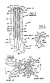
- the support ribs have extended from the airfoil forming skin of the airfoil halves 3, 3 ⁇ substantially normal or perpendicular thereto; e.g., as shown in Figs. 1 and 2 where internal support ribs 1, 1 ⁇ are shown extending substantially normal to the airfoil-forming skins 2, 2 ⁇ of the respective airfoil halves 3, 3 ⁇ along the length of the ribs from adjacent the root 4 toward the tip 5 of the airfoil. It is apparent from Figs. 1 and 2 that the airfoil of each half is highly twisted transversely along its longitudinal axis from adjacent the root 4 toward the tip 5.
- the support ribs 1, 1 ⁇ including their bonding surfaces 1a, 1a ⁇ , twist or spiral transversely from the root toward the tip and complicate the bonding process to join airfoil halves 3 and 3 ⁇ at the bonding surfaces provided on the ribs.
- the bonding dies receiving the mated airfoil halves will require a very close fit between mating die parts to maintain accurate bonding alignment between the rib bonding surfaces and very low bonding loads or forces must be used to press the dies and airfoil halves together to prevent deformation of the rib bonding surfaces 1a which are not normal to the direction of the bonding pressure.
- longer bonding times are required to diffusion bond the airfoil halves together; e.g., typical bonding times could be 4-6 hours with airfoil components having transversely twisted ribs.
- the invention contemplates an airfoil component or half having a skin or shell configured in the form of a partial airfoil twisted transversely along its longitudinal axis and having one or more support ribs extending from the skin with each rib terminating in a bonding surface that is not transversely twisted along its longitudinal axis such that axes normal to the bonding surface along its length are substantially parallel to one another when viewed along the longitudinal axis or direction of the airfoil.
- each support rib substantially along its length extends from the skin in other than a normal orientation and instead extends normal to a bonding plane defined by the bonding surface of the rib or ribs.
- Such an airfoil component can be forged at relatively low cost.
- the invention further contemplates an airfoil member comprising a pair of the airfoil components of either of the preceding paragraphs bonded together at the bonding surfaces to provide a twisted hollow airfoil member with one or more non-twisted internal support ribs between the skins.
- the invention still further contemplates a method for making the airfoil member of the preceding paragraph including forming a pair of airfoil components of preceding paragraphs, preferably by forging, and bonding the components together between dies that move toward one another under bonding pressure in a direction substantially normal to the bonding surfaces of the non-twisted airfoil support ribs.
- a method for making the airfoil member of the preceding paragraph including forming a pair of airfoil components of preceding paragraphs, preferably by forging, and bonding the components together between dies that move toward one another under bonding pressure in a direction substantially normal to the bonding surfaces of the non-twisted airfoil support ribs.
- Figure 3 illustrates an airfoil component 20, such as a blade half or vane half, made in accordance with the present invention.
- the airfoil component 20 includes a root section 22, platform section 23 and airfoil section 24 terminating in tip 25.
- the airfoil component comprises a half of the ultimate airfoil member 80 to be produced, see Figs. 4 and 7.
- the airfoil component 20 includes longitudinally extending channels 26 extending from the root section to the tip section which may, if desired, form longitudinal cooling passages 27 in the bonded airfoil member for conducting cooling fluid such as air flow therethrough. Or, passages 27 may simply be used to reduce weight of the airfoil member 80.
- the root section 22 includes a "fir tree' portion 30 for receipt in a complementary "fir tree” slot in a disc or hub (not shown) as is well known.
- the root section 22 in the as-forged condition is oversized and final machining thereof to finished tolerance is conducted after the airfoil member 80 formed bonding components 20, 20 ⁇ together.
- the airfoil section 24 includes a skin on shell 32 configured as half of an airfoil form twisted transversely along the longitudinal axis L of the airfoil section (also known as the centerline or stacking line of the airfoil).
- the transverse twist along the length of the airfoil is especially clear from Fig. 4 for the bonded airfoil member 80 where a cross-section of the airfoil section near and above root section 22 is shown with a cross-section of the airfoil section near the tip 25 superimposed thereover.
- the direction of the transverse twist is indicated by the arrows on Fig. 4.
- the skin or shell 32 includes outer partial airfoil surface 34 that together with the outer airfoil surface 34 ⁇ on mating airfoil component 20 ⁇ define the total airfoil for the blade or vane.
- the skin or shell 32 includes on the inner side 38 leading edge or peripheral bonding surface 40 and trailing edge or peripheral bonding surface 42 which are twisted transversely along the longitudinal axis L of the airfoil, Fig. 4, and which ultimately are bonded to similar leading and trailing edge bonding surfaces 40 ⁇ , 42 ⁇ , respectively, on the mating airfoil component 20 ⁇ .
- leading and trailing bonding surfaces 40, 42 are the longitudinally extending internal support ribs 50, 52, 54 which are spaced apart chord-wise of the airfoil to form the fluid channels 26 therebetween.
- the support ribs 50, 52, 54 do not twist transversely along their longitudinal axis or length as the partial airfoil skin 32 and leading and trailing bonding surfaces 40, 42 do.
- Root section 22 includes leading and trailing bonding surfaces 60, 62 and intermediate bonding surface 64 for bonding and mating to similar complementary surfaces on the root section 22 ⁇ of the other airfoil component 20 ⁇ . Bonding surfaces 60, 62, 64 on root section 22 and those on the mating root section 22 ⁇ may be transversely twisted.
- the support ribs, 50, 52, 54 of the airfoil component 20 do not twist transversely along and about the longitudinal axis L of the airfoil. This non-twist is best seen in Fig. 4.
- each rib 50, 52, 54 extends laterally from inner side 38 of the skin 32 substantially along its length at other than a normal or perpendicular relation to the skin 32 or a tangent to the skin at areas of intersection.
- a lateral plane or cross-section along the length of each rib that (the plane) includes a tangent line to the airfoil skin which tangent line is parallel to the respective rib bonding plane.
- each rib will extend substantially normal to the airfoil skin 32.
- the lateral plane where each rib will be substantially normal to the skin will be approximately at the center or mid-point of the length of each rib.
- each rib is referred to as extending at other than a normal orientation or relation to the skin substantially along the rib length with "substantially" used to account for this exception at the lateral plane.
- each support rib When viewed at any given lateral cross-section through the airfoil as in Fig. 4, each support rib extends substantially along its length substantially normal or perpendicular to a bonding plane defined by each of the bonding surfaces 50a, 52a, 54a, respectively, in which each rib terminates. This is in contrast to the prior art practice of having the support ribs extend from the skin substantially normal or perpendicular to the skin.
- each bonding surface 50a, 52a, 54a is also not twisted transversely along its length or longitudinal axis such that axes normal to each bonding surface are substantially parallel to one another when viewed along the longitudinal axis or direction of the airfoil and to the same given longitudinal plane LL through the airfoil.
- the bonding surface of each rib lies in respective transverse planes T 1, T 2 that are substantially parallel with one another when viewed transversely from the leading edge towards the trailing edge and vice versa and with the same transverse plane T.
- the bonding surfaces of each rib 50, 52, 54 are in transverse planes that are substantially parallel with one another and the same transverse plane T.
- Fig. 4 shows that the sidewalls 50b, 50c; 52b, 52c and 54b, 54c defining each rib are substantially parallel with one another along the length of the rib and are substantially normal to the respective bonding surface 50a, 52a, 54a.
- the sidewalls are referred to as substantially parallel with one another and substantially normal to the bonding plane since in fact each sidewall will be slightly relieved or tapered as it extends from the skin in a manner and extent sufficient to allow release of the forging die therefrom.
- airfoil skin 32 ⁇ of airfoil component 20 ⁇ is suitably configured to form the desired overall airfoil shape for the airfoil member, such as a blade or vane, when the airfoil components 20, 20 ⁇ are bonded together.
- the desired overall airfoil shape or contour depending on individual gas turbine engine designs.
- each support rib is shown in Fig. 5 where it can be seen that one sidewall 60b is perpendicular to bonding surface 60a while the other sidewall 60c is inclined at an angle to the bonding surface 60a to provide additional rib thickness at the base adjacent the skin 32 for further support, strength and rigidity at the junction of the rib with the skin.
- the bonding surface 60a in this embodiment is like those described hereinabove in that it is not transversely twisted along the longitudinal axis.
- airfoil components 20, 20 ⁇ made in accordance with the invention are that each airfoil component can be forged from suitable metals or alloys; e.g., titanium, titanium alloys, nickel or cobalt base superalloys or others, with the internal support ribs shown by known techniques to near net shape or shapes requiring a minimum of stock removal by machining.
- suitable metals or alloys e.g., titanium, titanium alloys, nickel or cobalt base superalloys or others
- the internal support ribs shown by known techniques to near net shape or shapes requiring a minimum of stock removal by machining.
- As forged airfoil components 20, 20 ⁇ can thus be produced on a relatively low cost basis compared to complete machining thereof, for example, with intricate or close tolerance and easily inspected internal details, e.g., cooling passages 26, since the inner side 38 is available for working by forging and inspection.
- the highly transversely twisted airfoil component having highly transversely twisted support ribs as shown in Fig. 1 cannot be produced by forging as a result of the transverse twist on the support ribs.
- the present invention imparts forgeability to the airfoil components 20, 20 ⁇ , not previously available.
- the bonded airfoil member 80 of Fig. 7 is produced by diffusion bonding airfoil components 20, 20 ⁇ together at the various bonding surfaces described hereinabove on the root section 22 and airfoil section 24 under high temperature and pressure.
- the airfoil components 20, 20 ⁇ are placed between female dies 70, 72 made of a "hard" material such as nickel base superalloy or molybdenum that do not plastically deform at the particular bonding temperature and pressure involved, Fig. 6.
- the various bonding surfaces on airfoil components 20, 20 ⁇ are aligned and abutted as shown in Fig. 6 during such metallurgical bonding.
- the female dies 70, 72 can be loaded or forced together in a hydraulic press or other force applying device to apply bonding pressure across the various bonding surfaces in a single direction although in opposite senses; i.e., substantially normal to bonding surfaces 50a, 50a ⁇ ; 52a, 52a ⁇ and 54a, 54a ⁇ , Fig. 6. High bonding pressure can be applied since it is normal to those rib bonding surfaces. In this way, bonding time can be relatively short, e.g., about 15 minutes, compared to the longer times, e.g., 4-6 hours, required in the prior art method where lower bonding pressure must be used when the ribs are transversely twisted along their lengths.
- diffusion bonding pressure and bonding temperature will depend on the alloy or material from which airfoil components 20, 20 ⁇ are forged.
- Conventional heating devices such as resistance elements, induction or external furnaces can be used to heat the dies and airfoil components for bonding.
- Other bonding processes may be used as well including, but not limiting to, transient liquid phase bonding.
Landscapes
- Engineering & Computer Science (AREA)
- Mechanical Engineering (AREA)
- General Engineering & Computer Science (AREA)
- Architecture (AREA)
- Pressure Welding/Diffusion-Bonding (AREA)
- Turbine Rotor Nozzle Sealing (AREA)
- Forging (AREA)
Applications Claiming Priority (2)
| Application Number | Priority Date | Filing Date | Title |
|---|---|---|---|
| US926152 | 1986-11-03 | ||
| US06/926,152 US4815939A (en) | 1986-11-03 | 1986-11-03 | Twisted hollow airfoil with non-twisted internal support ribs |
Publications (2)
| Publication Number | Publication Date |
|---|---|
| EP0266954A2 true EP0266954A2 (de) | 1988-05-11 |
| EP0266954A3 EP0266954A3 (de) | 1990-01-24 |
Family
ID=25452822
Family Applications (1)
| Application Number | Title | Priority Date | Filing Date |
|---|---|---|---|
| EP87309488A Withdrawn EP0266954A3 (de) | 1986-11-03 | 1987-10-27 | Verwundene Hohlschaufel mit nichtverwundenen inneren Verstärkungsrippen |
Country Status (3)
| Country | Link |
|---|---|
| US (1) | US4815939A (de) |
| EP (1) | EP0266954A3 (de) |
| JP (1) | JPS6487803A (de) |
Cited By (11)
| Publication number | Priority date | Publication date | Assignee | Title |
|---|---|---|---|---|
| FR2675535A1 (fr) * | 1991-04-16 | 1992-10-23 | Gen Electric | Ailette a partie centrale interieure creuse. |
| EP0520714A1 (de) * | 1991-06-24 | 1992-12-30 | General Electric Company | Durch Photoätzung hergestellte Kühlrillen für diffusionsverbundene Schaufeln |
| GB2264149A (en) * | 1992-02-13 | 1993-08-18 | Preci Spark Ltd | Reinforced turbocharger vane. |
| US5253824A (en) * | 1991-04-16 | 1993-10-19 | General Electric Company | Hollow core airfoil |
| US5419040A (en) * | 1994-04-29 | 1995-05-30 | United Technologies Corporation | Hollow fan blade fabrication |
| WO1995022685A1 (en) * | 1994-02-22 | 1995-08-24 | United Technologies Corporation | Hollow fan blade dovetail |
| US5509783A (en) * | 1993-02-09 | 1996-04-23 | Preci-Spark, Ltd. | Reinforced vane |
| EP1600251A1 (de) * | 2004-04-29 | 2005-11-30 | United Technologies Corporation | Verfahren zum Doppelschmieden eines Artikels mit nahezu Fertigmassen |
| EP1760264A3 (de) * | 2005-08-31 | 2010-04-21 | United Technologies Corporation | Turbinenelement und Verfahren zu seiner Herstellung |
| EP1760265A3 (de) * | 2005-08-31 | 2010-04-21 | United Technologies Corporation | Schaufel mit Mikrokühlkreislauf und entsprechendes Herstellungsverfahren |
| EP3088667A1 (de) * | 2015-04-29 | 2016-11-02 | Siemens Aktiengesellschaft | Turbinenschaufel mit querrippen |
Families Citing this family (37)
| Publication number | Priority date | Publication date | Assignee | Title |
|---|---|---|---|---|
| JPH01313602A (ja) * | 1988-06-10 | 1989-12-19 | Agency Of Ind Science & Technol | 空気穴付タービンブレードの製造方法 |
| JPH0445149U (de) * | 1990-08-21 | 1992-04-16 | ||
| US5246340A (en) * | 1991-11-19 | 1993-09-21 | Allied-Signal Inc. | Internally cooled airfoil |
| GB2270718A (en) * | 1992-09-22 | 1994-03-23 | Rolls Royce Plc | Single crystal turbine blades having pedestals. |
| US5439354A (en) * | 1993-06-15 | 1995-08-08 | General Electric Company | Hollow airfoil impact resistance improvement |
| US5503532A (en) * | 1994-11-14 | 1996-04-02 | General Electric Company | Diffusion bonded airfoil and method |
| US5584660A (en) * | 1995-04-28 | 1996-12-17 | United Technologies Corporation | Increased impact resistance in hollow airfoils |
| DE19542080C1 (de) * | 1995-11-11 | 1997-01-30 | Mtu Muenchen Gmbh | Schaufelblatt für Turbotriebwerke zur Herstellung von Laufrädern mit integralen Hohlschaufeln |
| EP1283325A1 (de) * | 2001-08-09 | 2003-02-12 | Siemens Aktiengesellschaft | Schaufel einer Strömungsmaschine und Verfahren zur Herstellung einer solchen Schaufel |
| FR2855441B1 (fr) * | 2003-05-27 | 2006-07-14 | Snecma Moteurs | Aube creuse pour turbomachine et procede de fabrication d'une telle aube. |
| GB0425137D0 (en) * | 2004-11-13 | 2004-12-15 | Rolls Royce Plc | Blade |
| JP4719596B2 (ja) * | 2006-03-14 | 2011-07-06 | 西部電機株式会社 | 工作機械の主軸台装置 |
| US7517198B2 (en) | 2006-03-20 | 2009-04-14 | Modular Wind Energy, Inc. | Lightweight composite truss wind turbine blade |
| US20090074576A1 (en) * | 2006-04-20 | 2009-03-19 | Florida Turbine Technologies, Inc. | Turbine blade with cooling breakout passages |
| GB0700499D0 (en) * | 2007-01-11 | 2007-02-21 | Rolls Royce Plc | Aerofoil configuration |
| US20090060714A1 (en) * | 2007-08-30 | 2009-03-05 | General Electric Company | Multi-part cast turbine engine component having an internal cooling channel and method of forming a multi-part cast turbine engine component |
| JP5853364B2 (ja) * | 2010-12-15 | 2016-02-09 | 日産自動車株式会社 | 接合方法、接合装置 |
| US9249668B2 (en) | 2012-04-24 | 2016-02-02 | United Technologies Corporation | Airfoil with break-way, free-floating damper member |
| US9296039B2 (en) | 2012-04-24 | 2016-03-29 | United Technologies Corporation | Gas turbine engine airfoil impingement cooling |
| US9267380B2 (en) | 2012-04-24 | 2016-02-23 | United Technologies Corporation | Airfoil including loose damper |
| US9181806B2 (en) | 2012-04-24 | 2015-11-10 | United Technologies Corporation | Airfoil with powder damper |
| US9243502B2 (en) | 2012-04-24 | 2016-01-26 | United Technologies Corporation | Airfoil cooling enhancement and method of making the same |
| US9121286B2 (en) | 2012-04-24 | 2015-09-01 | United Technologies Corporation | Airfoil having tapered buttress |
| US9074482B2 (en) | 2012-04-24 | 2015-07-07 | United Technologies Corporation | Airfoil support method and apparatus |
| US9175570B2 (en) | 2012-04-24 | 2015-11-03 | United Technologies Corporation | Airfoil including member connected by articulated joint |
| US8915718B2 (en) | 2012-04-24 | 2014-12-23 | United Technologies Corporation | Airfoil including damper member |
| US9470095B2 (en) | 2012-04-24 | 2016-10-18 | United Technologies Corporation | Airfoil having internal lattice network |
| US9133712B2 (en) | 2012-04-24 | 2015-09-15 | United Technologies Corporation | Blade having porous, abradable element |
| US9404369B2 (en) | 2012-04-24 | 2016-08-02 | United Technologies Corporation | Airfoil having minimum distance ribs |
| ITCO20120059A1 (it) * | 2012-12-13 | 2014-06-14 | Nuovo Pignone Srl | Metodi per produrre pale cave sagomate in 3d di turbomacchine mediante produzione additiva, pale cave di turbomacchina e turbomacchine |
| US9120144B2 (en) | 2013-02-06 | 2015-09-01 | Siemens Aktiengesellschaft | Casting core for twisted gas turbine engine airfoil having a twisted rib |
| US9057276B2 (en) | 2013-02-06 | 2015-06-16 | Siemens Aktiengesellschaft | Twisted gas turbine engine airfoil having a twisted rib |
| WO2015047698A1 (en) * | 2013-09-24 | 2015-04-02 | United Technologies Corporation | Bonded multi-piece gas turbine engine component |
| US10774653B2 (en) | 2018-12-11 | 2020-09-15 | Raytheon Technologies Corporation | Composite gas turbine engine component with lattice structure |
| US11149550B2 (en) | 2019-02-07 | 2021-10-19 | Raytheon Technologies Corporation | Blade neck transition |
| US10871074B2 (en) | 2019-02-28 | 2020-12-22 | Raytheon Technologies Corporation | Blade/vane cooling passages |
| CN116853488B (zh) * | 2023-07-18 | 2025-12-05 | 中国航发沈阳发动机研究所 | 一种升力风扇转子轮盘及其叶片结构 |
Family Cites Families (11)
| Publication number | Priority date | Publication date | Assignee | Title |
|---|---|---|---|---|
| US1786307A (en) * | 1928-12-17 | 1930-12-23 | Hobart R Kriegh | Aeroplane |
| US1818519A (en) * | 1929-06-21 | 1931-08-11 | Lewis G Young | Aerofoil construction |
| US2210642A (en) * | 1938-05-27 | 1940-08-06 | Stephen W Thompson | Aircraft |
| US3736638A (en) * | 1971-04-07 | 1973-06-05 | United Aircraft Corp | Method for bonding opposed parts of a hollow article together |
| US4089456A (en) * | 1977-06-28 | 1978-05-16 | United Technologies Corporation | Controlled-pressure diffusion bonding and fixture therefor |
| US4364160A (en) * | 1980-11-03 | 1982-12-21 | General Electric Company | Method of fabricating a hollow article |
| DE3113079C2 (de) * | 1981-04-01 | 1985-11-21 | Messerschmitt-Bölkow-Blohm GmbH, 8000 München | Aerodynamischer Groß-Flügel und Verfahren zu dessen Herstellung |
| GB2095589B (en) * | 1981-04-01 | 1984-08-01 | Rolls Royce | Method of making a blade for a gas turbine engine |
| FR2516165B1 (fr) * | 1981-11-10 | 1986-07-04 | Snecma | Aube de turbine a gaz a chambre de refroidissement par circulation de fluide et son procede de realisation |
| US4501053A (en) * | 1982-06-14 | 1985-02-26 | United Technologies Corporation | Method of making rotor blade for a rotary machine |
| US4512069A (en) * | 1983-02-04 | 1985-04-23 | Motoren-Und Turbinen-Union Munchen Gmbh | Method of manufacturing hollow flow profiles |
-
1986
- 1986-11-03 US US06/926,152 patent/US4815939A/en not_active Expired - Lifetime
-
1987
- 1987-10-27 EP EP87309488A patent/EP0266954A3/de not_active Withdrawn
- 1987-11-02 JP JP62275922A patent/JPS6487803A/ja active Granted
Cited By (14)
| Publication number | Priority date | Publication date | Assignee | Title |
|---|---|---|---|---|
| FR2675535A1 (fr) * | 1991-04-16 | 1992-10-23 | Gen Electric | Ailette a partie centrale interieure creuse. |
| US5253824A (en) * | 1991-04-16 | 1993-10-19 | General Electric Company | Hollow core airfoil |
| EP0520714A1 (de) * | 1991-06-24 | 1992-12-30 | General Electric Company | Durch Photoätzung hergestellte Kühlrillen für diffusionsverbundene Schaufeln |
| GB2264149A (en) * | 1992-02-13 | 1993-08-18 | Preci Spark Ltd | Reinforced turbocharger vane. |
| GB2264149B (en) * | 1992-02-13 | 1995-07-05 | Preci Spark Ltd | Reinforced vane |
| US5509783A (en) * | 1993-02-09 | 1996-04-23 | Preci-Spark, Ltd. | Reinforced vane |
| WO1995022685A1 (en) * | 1994-02-22 | 1995-08-24 | United Technologies Corporation | Hollow fan blade dovetail |
| US5419040A (en) * | 1994-04-29 | 1995-05-30 | United Technologies Corporation | Hollow fan blade fabrication |
| EP1600251A1 (de) * | 2004-04-29 | 2005-11-30 | United Technologies Corporation | Verfahren zum Doppelschmieden eines Artikels mit nahezu Fertigmassen |
| EP1760264A3 (de) * | 2005-08-31 | 2010-04-21 | United Technologies Corporation | Turbinenelement und Verfahren zu seiner Herstellung |
| EP1760265A3 (de) * | 2005-08-31 | 2010-04-21 | United Technologies Corporation | Schaufel mit Mikrokühlkreislauf und entsprechendes Herstellungsverfahren |
| EP1760265B1 (de) | 2005-08-31 | 2015-07-15 | United Technologies Corporation | Bauteil eines Turbinentriebwerks mit einem Mikrokühlkreislauf und zugehöriges Herstellungsverfahren |
| EP3088667A1 (de) * | 2015-04-29 | 2016-11-02 | Siemens Aktiengesellschaft | Turbinenschaufel mit querrippen |
| WO2016173916A1 (de) * | 2015-04-29 | 2016-11-03 | Siemens Aktiengesellschaft | Turbinenschaufel mit querrippen |
Also Published As
| Publication number | Publication date |
|---|---|
| JPS6487803A (en) | 1989-03-31 |
| US4815939A (en) | 1989-03-28 |
| EP0266954A3 (de) | 1990-01-24 |
| JPH0567763B2 (de) | 1993-09-27 |
Similar Documents
| Publication | Publication Date | Title |
|---|---|---|
| US4815939A (en) | Twisted hollow airfoil with non-twisted internal support ribs | |
| US5407326A (en) | Hollow blade for a turbomachine | |
| EP0475882B1 (de) | Herstellung eines Metallhohlkörpers | |
| US5269058A (en) | Design and processing method for manufacturing hollow airfoils | |
| US5469618A (en) | Method for manufacturing hollow airfoils (two-piece concept) | |
| US3768147A (en) | Method of friction welding | |
| US6003756A (en) | Airfoil for gas a turbine engine and method of manufacture | |
| US5636440A (en) | Process for manufacturing a hollow blade for a turbo-machine | |
| US5197190A (en) | Fabrication of repair method for an integrally bladed rotor | |
| US5243758A (en) | Design and processing method for manufacturing hollow airfoils (three-piece concept) | |
| US5253419A (en) | Method of manufacturing a hollow blade for a turboshaft engine | |
| US5826332A (en) | Method and manufacturing a hollow turbomachine blade | |
| JP4732718B2 (ja) | 鍛造チタン製圧縮機羽根車を製造するための工程 | |
| US4529452A (en) | Process for fabricating multi-alloy components | |
| US6467168B2 (en) | Method of manufacturing an article by diffusion bonding and superplastic forming | |
| US4043498A (en) | Method of plastic flow diffusion bonding | |
| US4536932A (en) | Method for eliminating low cycle fatigue cracking in integrally bladed disks | |
| US7441331B2 (en) | Turbine engine component manufacture methods | |
| JP3291827B2 (ja) | 羽根車及びディフューザ、並びにその製作方法 | |
| US3982854A (en) | Friction welded metallic turbomachinery blade element | |
| CA2021625A1 (en) | Alloy turbine disk | |
| EP1338353A1 (de) | Verfahren zur Herstellung eines Gegenstandes durch Diffusionsschweissung und superplastische Formung | |
| US3588980A (en) | Method for making a contoured article | |
| JP2001082388A (ja) | 塑性成形ハイブリッド翼形部 | |
| JPS63263203A (ja) | 羽根板,羽根基部及びカバープレート又はカバーバンドから成る回転熱機関用羽根をカバープレートを固定することにより製造する方法及びこの方法により製造される羽根 |
Legal Events
| Date | Code | Title | Description |
|---|---|---|---|
| PUAI | Public reference made under article 153(3) epc to a published international application that has entered the european phase |
Free format text: ORIGINAL CODE: 0009012 |
|
| AK | Designated contracting states |
Kind code of ref document: A2 Designated state(s): DE FR GB |
|
| PUAL | Search report despatched |
Free format text: ORIGINAL CODE: 0009013 |
|
| AK | Designated contracting states |
Kind code of ref document: A3 Designated state(s): DE FR GB |
|
| RHK1 | Main classification (correction) |
Ipc: F01D 5/18 |
|
| 17P | Request for examination filed |
Effective date: 19900306 |
|
| 17Q | First examination report despatched |
Effective date: 19910410 |
|
| STAA | Information on the status of an ep patent application or granted ep patent |
Free format text: STATUS: THE APPLICATION IS DEEMED TO BE WITHDRAWN |
|
| 18D | Application deemed to be withdrawn |
Effective date: 19940430 |
|
| RIN1 | Information on inventor provided before grant (corrected) |
Inventor name: DOBLE, GORDON S. |