EP0267231B1 - Persönliche speicherkarte - Google Patents
Persönliche speicherkarte Download PDFInfo
- Publication number
- EP0267231B1 EP0267231B1 EP87903066A EP87903066A EP0267231B1 EP 0267231 B1 EP0267231 B1 EP 0267231B1 EP 87903066 A EP87903066 A EP 87903066A EP 87903066 A EP87903066 A EP 87903066A EP 0267231 B1 EP0267231 B1 EP 0267231B1
- Authority
- EP
- European Patent Office
- Prior art keywords
- card
- reader
- writer
- data
- data card
- Prior art date
- Legal status (The legal status is an assumption and is not a legal conclusion. Google has not performed a legal analysis and makes no representation as to the accuracy of the status listed.)
- Expired - Lifetime
Links
Images



Classifications
-
- G—PHYSICS
- G06—COMPUTING OR CALCULATING; COUNTING
- G06K—GRAPHICAL DATA READING; PRESENTATION OF DATA; RECORD CARRIERS; HANDLING RECORD CARRIERS
- G06K19/00—Record carriers for use with machines and with at least a part designed to carry digital markings
- G06K19/06—Record carriers for use with machines and with at least a part designed to carry digital markings characterised by the kind of the digital marking, e.g. shape, nature, code
-
- G—PHYSICS
- G06—COMPUTING OR CALCULATING; COUNTING
- G06K—GRAPHICAL DATA READING; PRESENTATION OF DATA; RECORD CARRIERS; HANDLING RECORD CARRIERS
- G06K7/00—Methods or arrangements for sensing record carriers, e.g. for reading patterns
- G06K7/10—Methods or arrangements for sensing record carriers, e.g. for reading patterns by electromagnetic radiation, e.g. optical sensing; by corpuscular radiation
- G06K7/10009—Methods or arrangements for sensing record carriers, e.g. for reading patterns by electromagnetic radiation, e.g. optical sensing; by corpuscular radiation sensing by radiation using wavelengths larger than 0.1 mm, e.g. radio-waves or microwaves
- G06K7/10316—Methods or arrangements for sensing record carriers, e.g. for reading patterns by electromagnetic radiation, e.g. optical sensing; by corpuscular radiation sensing by radiation using wavelengths larger than 0.1 mm, e.g. radio-waves or microwaves using at least one antenna particularly designed for interrogating the wireless record carriers
- G06K7/10326—Methods or arrangements for sensing record carriers, e.g. for reading patterns by electromagnetic radiation, e.g. optical sensing; by corpuscular radiation sensing by radiation using wavelengths larger than 0.1 mm, e.g. radio-waves or microwaves using at least one antenna particularly designed for interrogating the wireless record carriers the antenna being of the very-near field type, e.g. capacitive
-
- G—PHYSICS
- G06—COMPUTING OR CALCULATING; COUNTING
- G06K—GRAPHICAL DATA READING; PRESENTATION OF DATA; RECORD CARRIERS; HANDLING RECORD CARRIERS
- G06K19/00—Record carriers for use with machines and with at least a part designed to carry digital markings
- G06K19/06—Record carriers for use with machines and with at least a part designed to carry digital markings characterised by the kind of the digital marking, e.g. shape, nature, code
- G06K19/067—Record carriers with conductive marks, printed circuits or semiconductor circuit elements, e.g. credit or identity cards also with resonating or responding marks without active components
- G06K19/07—Record carriers with conductive marks, printed circuits or semiconductor circuit elements, e.g. credit or identity cards also with resonating or responding marks without active components with integrated circuit chips
- G06K19/0723—Record carriers with conductive marks, printed circuits or semiconductor circuit elements, e.g. credit or identity cards also with resonating or responding marks without active components with integrated circuit chips the record carrier comprising an arrangement for non-contact communication, e.g. wireless communication circuits on transponder cards, non-contact smart cards or RFIDs
-
- G—PHYSICS
- G07—CHECKING-DEVICES
- G07C—TIME OR ATTENDANCE REGISTERS; REGISTERING OR INDICATING THE WORKING OF MACHINES; GENERATING RANDOM NUMBERS; VOTING OR LOTTERY APPARATUS; ARRANGEMENTS, SYSTEMS OR APPARATUS FOR CHECKING NOT PROVIDED FOR ELSEWHERE
- G07C9/00—Individual registration on entry or exit
- G07C9/20—Individual registration on entry or exit involving the use of a pass
- G07C9/28—Individual registration on entry or exit involving the use of a pass the pass enabling tracking or indicating presence
Definitions
- This invention relates to portable data cards.
- the use of credit cards for purchases and for banking and other transactions has become so popular that most travelers today do so with very little cash.
- the card typically made of plastic embossed with an account number and the name of the account owner, serves solely to identify an authorized account at a bank or credit house to be charged for a transaction.
- a magnetic stripe on the back of some cards contains the same information, but is machine-readable to speed the transaction. All accounting information is stored at the bank or credit house.
- the card could, therefore, carry personal identification data to virtually eliminate fraudulent use -- such data as personal characteristics, driver license, social security number, personal identification numbers, and even a voice print.
- the card could also carry the account numbers of all of the owner's charge accounts, the balances of all of the accounts, the credit limits of all of the accounts, and other such personal data as, for example, the sizes of family members for clothing purchases, personal telephone directories, etc.
- the types of personal data are limited only by one's imagination.
- Smart cards known in the art are being read and written into by various contact methods.
- One problem that arises if metallic contacts are used, however, is increased ohmic resistance due to the oxidation that takes place over time on the contact surfaces. This is of concern since the accuracy of the data transfer between a card and a reader or writer device decreases as the ohmic resistance of these contacts increases.
- the contacts while in the exposed position, allow air-borne particles to deposit on the surfaces decreasing the contact area and causing intermittent connections. Inasmuch as operating power for reading and writing into a card is also transferred from an associated station in a system to the card via these contacts, there is a loss in the amount of energy transferred after some time of use, rendering the card inoperative.
- a second problem associated with the use of metallic contacts in providing operating power and data onto the smart cards is the possibility of electrostatic discharge (ESD) occurring which can damage the microelectronics on the card.
- ESD electrostatic discharge
- High voltages that build up on a person or card or that are inadvertently coupled thereto from other sources may very easily be coupled directly to the electronics on the card when metallic contacts are used.
- Clamping diodes employed at the various inputs of a card provide some measure of protection, but are not capable of protecting against some of the higher voltage levels a card might occasionally encounter during normal use in its expected environment.
- USA patent no. 4277837 discloses a portable data card which includes means for storing data, and means for communicating with a card reader/writer, such means including capacitive coupling means for transferring data to and from the reader/writer, and magnetic coupling means for transferring energy from the reader/writer to the card to energise same.
- a personal memory card embodying the Invention may be the size of a standard plastic credit card and may be used in a variety of applications, from custom repertory dialing to storage of individual medical and/or banking records. Although the card looks and feels much like an ordinary credit card, the personal memory card includes a computer, an electrically erasable field programmable read-only memory, and also circuitry for receiving a combined power and timing signal and for receiving and transmitting data signals between the card and a reader/writer located in an associated station. No direct ohmic electrical contact is made between the card and the reader/writer for transferring power to the card or data to and from the card. Power to the card and data to and from the card are therefore reliably transferred even after some time of use.
- the personal memory card is also selectively reprogrammable by an authorized user at the associated station with new and different data as desired.
- FIG. 1 there is shown a block diagram of a portable data or personal memory card 10 being employed with a card reader/writer 15.
- a microcomputer 110 an electrically erasable programmable read-only memory (EEPROM) 115, an analog interface circuit 300, the secondary winding 121 of a transformer 120, and capacitive plates 125 to 128.
- EEPROM electrically erasable programmable read-only memory
- the microcomputer 110 includes a central processing unit and memory units in the form of random-access memory and read-only memory. Operating under firmware control provided by its internal read-only memory, the microcomputer 110 formats data to the EEPROM 115 and to the reader/writer 15 via the analog interface circuit 300. The microcomputer 110 also interprets commands from the reader/writer received through the analog interface 300. In addition, the microcomputer 110 checks for errors in reading and writing data to the EEPROM 115 and in transmissions to and from the reader/writer 15.
- EEPROM 115 By employing EEPROM 115 in the card 10, an authorized user has the ability to reprogram certain sections of the card while at an authorized associated application station with new and different data as desired.
- a memory is available from a number of suppliers, many of whom are mentioned in an article entitled "Are EEPROMS Finally Ready To Take Off?” by J. Robert Lineback, Electronics, Vol. 59, No. 7, (February 17, 1986), pp. 40-41.
- Data may be written to and read or erased from an EEPROM repeatedly while operating power is being applied. When operating power is removed, any changes made to the data in the EEPROM remain and is retrievable whenever the card 10 is again powered.
- the analog interface circuit 300 provides a means for interfacing the memory card 10 to the reader/writer 15. This interface performs a multitude of functions including providing operating power from magnetic energy coupled from the reader/writer 15 to the card 10, and also coupling data between the reader/writer 15 and the microcomputer 110 in the card 10. Power to the card 10 is provided from the reader/writer 15 to the analog interface circuit 300 via an inductive interface provided by the secondary winding 121 of a transformer 120. This transformer is formed when this secondary winding in the card 10 is mated to a primary winding 122 in the reader/writer 15.
- the transformer 120 may advantageously include a ferrite core 123 in the reader/writer for increased coupling between the transformer primary winding 122 and secondary winding 121.
- a second such core 124 may also be included in the transformer 120 and associated with the secondary winding 121 in the card for a further increase in coupling efficiency. In those arrangements where ample power is available and efficiency is not a consideration, one or both of these cores may be omitted.
- the use of a transformer for coupling power into a credit card was proposed by R. L. Billings in the U. S. patent entitled "Flexible Inductor", No. 4692604, filed on October 25, 1984.
- Data reception to and data transmission from the card 10 are provided to the analog interface 300 by a capacitive interface comprising four capacitors formed when electrodes or plates 125 through 128 on the memory card 10 are mated with corresponding electrodes or plates 155 through 158 in the reader/writer 15. Two of these capacitors are used to transfer data to the memory card 10 from the reader/writer 15 and the remaining two are used to transfer data to the reader/writer 15 from the card 10.
- the combination of the inductive interface and the capacitive interface provides the complete communication interface be tween the reader/writer 15 and the memory card 10.
- the analog interface circuit 300 is shown in greater detail in FIG. 3 and further described in the accompanying description later herein.
- the reader/writer 15 functionally mirror those in the card. Such components are, for example, an analog interface circuit 400 and a microcomputer 410.
- the reader/writer 15 also includes a power supply 162 and an input/output interface 160.
- the power supply 162 is used to provide power and also to couple a clock signal from the reader/writer 15 to the card 10 through the transformer 120.
- the input/output interface 160 is principally a universal asynchronous receiver transmitter (UART) and may be advantageously included in the microcomputer 410. This UART used for externally communicating with a suitably configured application station.
- UART universal asynchronous receiver transmitter
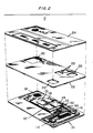
- the card generally comprises a laminated structure including a 0.005 inch (1 inch ⁇ 2.54 cm) thick single or double sided printed wiring board 201.
- Capacitive plates 125 through 128 are shown deployed on the top side of this printing wiring board, but it is understood that it is well within the capabilities of one skilled in the art to deploy these plates on the bottom or opposite side of the board as long as they are covered by a suitable insulator or dielectric sheet.
- Pads for bonding the analog interface circuit 300, microcomputer 110, EEPROM 115, transformer secondary 121 and surface-mounted capacitors 302 and 315 are located on the top side of board 201.
- the microcomputer 110 e., the microcomputer 110, EEPROM 115 and analog interface circuit 300, are wire bonded and the capacitors are conductively epoxied to the printed wiring board 201. It is to be understood that other means of electrically connecting the integrated circuits to the printed wiring board 201 are known to those skilled in the art. Tape automated bonding is an example of one such means.
- the printed wiring board 201 has laminated to it a structural member 202 which is approximately 0.020 inches thick (1 inch ⁇ 2.54 cm).
- This structural member has multiple openings 203 to accommodate the physical size of the above mentioned components which are mounted to the printing wiring board 201.
- a potting material is subsequently applied in sufficient quantity in the openings 203 of the structural member 202 to cover the components located therein and build up the slightly depressed upper surface of each of these components to align with the topmost surface of the structural member 202.
- a top cover sheet 204 is laminated to the structural member 202. To this cover sheet an appropriate label and logos are either affixed thereto or embedded therein.
- a dielectric sheet is also lamina ted to the bottom side of the double sided printed wiring board 201 thereby covering up the conductor leads (and possibly conductive plates) located on the lower side of this board that would otherwise be exposed. It is this lower exterior side of the card that generally has instructions and also a magnetic stripe and signature panel as desired.
- FIG. 3 there is shown in greater detail the analog interface circuit 300 of FIG. 1.
- This interface circuit such as power rectification and regulation, transmitting data to and receiving data from the reader/writer 15, obtaining a clock signal from the transformer secondary 121 for operation of the microcomputer 110 and also providing a power reset operation for resetting this microcomputer whenever power is removed and then reapplied to the memory card 10.
- Magnetically coupled from the reader/writer 15 through the transformer 120 to the secondary winding 121 is an approximate 1.8 megahertz AC signal.
- the output of this secondary winding 121 is applied to a full wave bridge rectifier 301.
- the DC voltage generated by the bridge rectifier 301 is filtered by a capacitor 302 and then coupled into a two-part regulator 303 which has a shunt regulator section on the front end and a series pass regulator on the back end .
- the shunt regulator serves to keep the current drawn out of the transformer secondary winding 121 fairly constant and thereby insures operation in an optimal area on the power transfer curve of transformer 120. This is desirable, since if the power demand in the card 10 decreases, the shunt regulator section dissipates the extra power to keep the load constant on the reader/writer 15 and on the transformer secondary winding 121 which is receiving the AC power. And if the power demand goes up in the card because an operation that requires greater power is occurring, the shunt regulator section reduces its power dissipation when it detects the voltage decreasing. The current then passes through the series-pass voltage regulator and provides operating power for all of the other circuitry in the card. Capacitor 315 provides additional filtering to the DC output of the shunt and series pass regulator 303.
- a clock recovery circuit 304 is coupled to the secondary winding 121 of the transformer 120 for providing a clock signal suitable for operation of the microcomputer 110.
- This circuit 304 comprises a comparator which differentially compares one side of the secondary winding 121 of the transformer 120 relative to the ground node of bridge rectifier 301. The pulses that are provided are shaped by the comparator giving relative fast turn-on and turn-off times suitable for driving the microcomputer 110.
- a reset circuit 305 comprising a voltage reference 306, a comparator 307 and a monostable multivibrator 308, monitors the regulated output of the shunt and series pass regulator 303. This circuit inhibits the operation of the microcomputer 110 if the supply voltage at the output of the shunt and series pass regulator 303 is not with in a predetermined operating range.
- a resistor string comprising resistors 309 and 310 form a divider circuit which reduces the voltage coupled to the comparator 307 from the regulator 303.
- the voltage reference 306 sets a threshold voltage level corresponding to the minimum allowable of the required operating level which is then compared with the voltage from the resistor string in comparator 307.
- the voltage provided to the comparator 307 from the voltage reference 306 is higher than the voltage provided to the comparator from the resistor string and the microcomputer remains reset.
- the output of the resistor string becomes higher that the voltage reference.
- the comparator 307 then switches states and the monostable multivibrator 308 provides a pulse of approximately 200 milliseconds in length to the microcomputer 110 which is enabled thereby and a processor contained therein starts running.
- the reset circuit 305 detects this decrease and again inhibits the microcomputer 110. This insures against extraneous operations which might occur and in some way affect the data in the EEPROM 115.
- the reset circuit 305 thus causes the microcomputer 110 to be inhibited whenever the voltage is less than the predetermine d operating voltage and therefore guards against improper operation of the card 10 in such low voltage state.
- a data out drive circuit 311, cam prising driver amplifiers 312 and 313, receive serial data from the microcomputer 110 and differentially drive the capacitive plates 125 and 126 which, respectively, interface with the capacitive plates 155 and 156 in the reader/writer 15.
- These drivers 312 and 313 convert the serial data from the microcomputer 110, which is of one polarity, into a differential polarity such that for each transition of the signal from the microcomputer 110, one of the drivers goes positive, while the other goes negative.
- a data receive circuit 320 is comprised of a differential amplifier and is used in receiving differential data coupled to the capacitive plates 127 and 128 from capacitive plates 157 and 158 in the reader/writer 15. This data from the reader/writer 15 is coupled to the microcomputer 110 in the card 10 for the appropriate processing.
- Hysteresis is built into the data receive circuit 320 such that a differential pulse greater than the hysteresis is all that is required to switch the output of the amplifier from a high state to a low state or from a low state to a high state.
- the hysteresis aids in preventing noise from causing false triggering of the data receive circuit by ignoring small differential noise signals and switching only on large differential data signals.
- FIG. 4 there is shown a schematic diagram illustrating in greater detail the major functional components of the reader writer 15 shown in FIG. 1.
- the memory card 10, shown schematically in FIG. 1 and graphically in FIG. 2, is shown in FIG. 4 in operable contact with the data and power couping components of the reader/writer 15. Power to the card is provided from the reader/writer 15 via the primary winding 122 of the transformer 120 formed when the secondary winding 121 in the card 10 is mated to the primary winding 122 in the reader/writer.
- the transfer of data between the reader/writer 15 and the card 10 is provided by a capacitive interface formed when plates 125 through 128 on the card are mated with corresponding plates 155 through 158 in the reader/writer 15.
- the reader/writer 15 has a number of components comparable in operation to those found in the memory card 10.
- the reader/writer 15 includes a data-out drive circuit comprising non-inverting driver amplifier 401 and inverting driver amplifier 402. These amplifiers receive serial data from a UART 403 and differentially drive the capacitive plates 157 and 158 which interface with the capacitive plates 127 and 128 in the card 10. Data for the memory card 10 is transmitted to the UART in parallel arrangement over an 8-bit bus 411 from a microcomputer 410.
- the reader/writer 15 also includes a data receive circuit 404 which is comprised of a differential amplifier and is used by the reader/writer 15 in receiving data coupled to the capacitive plates 155 and 156 from the capacitive plates 125 and 126 in the card 10.
- This serial data from the card 10 is coupled to the UART 403 where it is reformatted into parallel data and then coupled to the microcomputer 410 over the b-bit data bus 411.
- the microcomputer 410 through use of an internal UART reconverts the data into a serial format with start and stop bits before coupling the data to a particular application station 440 with which the card 10 and reader/writer 15 are configured to communicate.
- the application station may cam prise a number of configurations. It may be configured as a factory editing station, an office editing station, an issuer editing station, public telephone station, or any other station suitably configured for interacting with the card 10.
- a power driver 420 controls the power level that is transmitted into the primary winding 122 of the transformer 120.
- the power provided to the card 10 via the transformer secondary winding 121 is proportional to the current in this transformer primary winding 122.
- the amount of power being provided to the card 10 at any given time by the driver 420 is sampled in the transformer winding 122 and the information is provided to the analog-to digital converter 421.
- This converter provides to the microcomputer 410 a digital signal equivalent of the sampled analog power level.
- the microcomputer 410 adjusts the power going to the card 10 to the desired drive level with a signal provided to a digital-to-analog converter 422.
- the output of this digital-to-analog converter is coupled to a voltage regulator 423 which provides continually corrected drive power for the card 10 into the power driver 420. In this way, power into the card 10 is controlled to within the desired range for proper and efficient operation.
- a card-in sensor 425 is located approximately half way in the card slot. This is an optical sensor with illuminating and detecting elements. A mechanical arm is arranged to interrupt an optical beam generated by the illuminating element and being detected by the detecting element as the card progresses approximately half-way into the slot. This card-in sensor 425 provides a signal to the microcomputer 410 once a card is at the halfway point on its way in or on its way out of the station.
- a card fully-in sensor 426 is comparable to the card-in sensor in operation, but is located in the innermost part of the card slot. This sensor informs the microcomputer 410 when the card is fully seated in the card slot.
- the reader/writer 15 is conveniently designed to accommodate not only personal memory cards with reprogrammable microelectronics therein, but also cards that have only a magnetic stripe affixed thereto. Once a card is fully seated, a test is performed to determine if the card is a contactless personal memory card or a card having only a magnetic stripe. This test is initiated by having the microcomputer 410 apply power to the power driver 420. If power is drawn from the transformer primary winding 122, the reader/writer 15 assumes a memory card is in the slot. Otherwise, the reader/writer assumes that a magnetic stripe card occupies the slot.
- a solenoid 427 is activated by the microcomputer 410 in order to bring the communication interface in the reader/writer 15 in contact with the inserted card.
- the capacitive plates 155 through 158 and transformer primary 122 comprising this interface are mounted on a platen for deflectably positioning against the card by this solenoid in order to get the best capacitive and inductive coupling with the card. If the card fully-in sensor 426 is ever tripped because the card is partially pulled out, the solenoid 427 releases immediately so that the card can be easily withdrawn.
- the microcomputer 410 decides that the card just inserted is a magnetic stripe only card. The microcomputer 410 then provides an audible or visual signal to the user to remove the card. As the card is pulled from the slot, data on the magnetic stripe is read by a magnetic head 430, amplified by an amplifier 431 and then coupled into a serial port on the microcomputer 410.
- oscillator section 435 This section provides a clock signal for the microcomputer 410 and also provides an approximate 1.8 megahertz signal for the power driver 420. It is this signal that is detected by the clock recovery circuit 304 in FIG. 3 in order to provide a clock signal suitable for operating the microcomputer 110 in FIG. 1.
- a clock signal for the data transfer circuitry is also provided by the oscillator section 435 to the UART 403.
- This signal sets the data transfer rate between the card 10 and the reader/writer 15 at 19.2 kilobits per second.
- Such a data rate keeps the capacitive plates properly biased during the intervals between data bit transitions and thereby minimizes the susceptibility to noise in the communication interface between the card and the reader/writer due to voltage drift.
- the microcomputer 410 has additional memory in the form of an external random access memory (RAM) section 437 and an external read only memory (ROM) section 436.
- RAM random access memory
- ROM read only memory
- the ROM section may be easily replaced or augmented with an EEPROM section.
- Such an EEPROM section in the reader/writer 15 and/or in the station 440 is easily reprogrammed by data contained in a card when the card is brought in operable contact with the reader/writer 15.
- the microcomputer 410 communicates with the outside world via a serial data path to the station 440.
- This data path includes a transmit lead 441 and a receive lead 442. It also has an attention lead 443 which is activated by the card fully-in sensor 426. Finally, it also includes a reset lead 444 which enables the station 440 to reset the reader/writer 15 and initialize it into a known state. Power to the reader/writer 15 is also supplied by the station 440.
- An example of such a modification is a memory card operating in a system wherein data is communicated only from the memory card to a card reader.
- the memory card and/or an associated card reader are configured to have the minimal communication interface and microelectronics necessary to establish and maintain the flow of data from the card to the card reader.
Landscapes
- Engineering & Computer Science (AREA)
- Physics & Mathematics (AREA)
- General Physics & Mathematics (AREA)
- Theoretical Computer Science (AREA)
- Computer Networks & Wireless Communication (AREA)
- Health & Medical Sciences (AREA)
- Toxicology (AREA)
- Microelectronics & Electronic Packaging (AREA)
- Computer Hardware Design (AREA)
- Electromagnetism (AREA)
- General Health & Medical Sciences (AREA)
- Artificial Intelligence (AREA)
- Computer Vision & Pattern Recognition (AREA)
- Credit Cards Or The Like (AREA)
- Power Sources (AREA)
Claims (11)
Priority Applications (1)
| Application Number | Priority Date | Filing Date | Title |
|---|---|---|---|
| AT87903066T ATE73562T1 (de) | 1986-04-28 | 1987-04-03 | Persoenliche speicherkarte. |
Applications Claiming Priority (2)
| Application Number | Priority Date | Filing Date | Title |
|---|---|---|---|
| US856171 | 1986-04-28 | ||
| US06/856,171 US4795898A (en) | 1986-04-28 | 1986-04-28 | Personal memory card having a contactless interface using differential data transfer |
Publications (2)
| Publication Number | Publication Date |
|---|---|
| EP0267231A1 EP0267231A1 (de) | 1988-05-18 |
| EP0267231B1 true EP0267231B1 (de) | 1992-03-11 |
Family
ID=25322988
Family Applications (1)
| Application Number | Title | Priority Date | Filing Date |
|---|---|---|---|
| EP87903066A Expired - Lifetime EP0267231B1 (de) | 1986-04-28 | 1987-04-03 | Persönliche speicherkarte |
Country Status (7)
| Country | Link |
|---|---|
| US (1) | US4795898A (de) |
| EP (1) | EP0267231B1 (de) |
| JP (1) | JPH01500340A (de) |
| KR (1) | KR920002628B1 (de) |
| CA (1) | CA1292802C (de) |
| DE (1) | DE3777334D1 (de) |
| WO (1) | WO1987006747A1 (de) |
Families Citing this family (105)
| Publication number | Priority date | Publication date | Assignee | Title |
|---|---|---|---|---|
| US4816654A (en) † | 1986-05-16 | 1989-03-28 | American Telephone And Telegraph Company | Improved security system for a portable data carrier |
| JP2556501B2 (ja) * | 1987-02-09 | 1996-11-20 | 株式会社日立製作所 | 運転免許証カ−ドシステム |
| US4853523A (en) * | 1987-10-05 | 1989-08-01 | Pitney Bowes Inc. | Vault cartridge having capacitive coupling |
| US4802027A (en) * | 1987-10-05 | 1989-01-31 | Pitney Bowes Inc. | Data storage device coupled to a data storage interface |
| JP2597623B2 (ja) * | 1987-10-08 | 1997-04-09 | 株式会社トキメック | 電磁誘導結合による電源供給方式 |
| ATE131292T1 (de) * | 1988-02-04 | 1995-12-15 | Magellan Corp Australia | Shuntregelvorrichtung. |
| DK173030B1 (da) * | 1988-04-08 | 1999-11-22 | Toppan Printing Company Ltd | Informationskort, som kan kommunikeres på kontaktfri måde |
| BR8906949A (pt) * | 1988-05-04 | 1990-09-11 | Humble David Raymond | Sistema de contabilidade de transacao generica |
| DE3844367A1 (de) * | 1988-12-30 | 1990-07-05 | Bosch Gmbh Robert | Kraftstoffeinspritzpumpe fuer brennkraftmaschinen |
| US5247164A (en) * | 1989-01-26 | 1993-09-21 | Hitachi Maxell, Ltd. | IC card and portable terminal |
| JP2776929B2 (ja) * | 1989-03-29 | 1998-07-16 | 株式会社日立製作所 | カードデータ処理システム及びカードデータの処理方法 |
| WO1990014626A1 (en) * | 1989-05-15 | 1990-11-29 | Dallas Semiconductor Corporation | Systems with data-token/one-wire-bus |
| FR2654232A1 (fr) * | 1989-11-07 | 1991-05-10 | Europ Rech Electr Lab | Generateur de tensions continues pour l'alimentation d'une carte a circuit integre. |
| JPH03171384A (ja) * | 1989-11-30 | 1991-07-24 | Sony Corp | 情報読取装置 |
| JPH03189786A (ja) * | 1989-12-19 | 1991-08-19 | Sony Corp | 情報カード装置 |
| JP2548415B2 (ja) * | 1990-01-08 | 1996-10-30 | シャープ株式会社 | 電力供給装置 |
| JP2527267B2 (ja) * | 1990-04-19 | 1996-08-21 | 三菱電機株式会社 | 非接触型可搬担体 |
| JPH0832494B2 (ja) * | 1990-08-18 | 1996-03-29 | 三菱電機株式会社 | 携帯形半導体記憶装置 |
| US5237165A (en) * | 1991-04-05 | 1993-08-17 | Tingley Iii Loyal H | Multi-turn coil structures and methods of winding same |
| US5326476A (en) | 1991-04-19 | 1994-07-05 | Althin Medical, Inc. | Method and apparatus for kidney dialysis using machine with programmable memory |
| SE470149B (sv) | 1991-05-10 | 1993-11-15 | Televerket | Anordning för åtkomst av tjänster via telefonapparat |
| DE4292340B4 (de) * | 1991-07-17 | 2007-11-29 | Halpern, John Wolfgang | Ein elektronischer Pass |
| DE4207779A1 (de) * | 1992-03-11 | 1993-09-16 | Provera Ges Fuer Projektierung | Datentraeger |
| US5229652A (en) * | 1992-04-20 | 1993-07-20 | Hough Wayne E | Non-contact data and power connector for computer based modules |
| FR2691563B1 (fr) * | 1992-05-19 | 1996-05-31 | Francois Droz | Carte comprenant au moins un element electronique et procede de fabrication d'une telle carte. |
| US5310999A (en) * | 1992-07-02 | 1994-05-10 | At&T Bell Laboratories | Secure toll collection system for moving vehicles |
| US5412192A (en) * | 1993-07-20 | 1995-05-02 | American Express Company | Radio frequency activated charge card |
| US5364272A (en) * | 1993-08-09 | 1994-11-15 | Texas Instruments Incorporated | Apparatus and method for teaching |
| DE9313736U1 (de) * | 1993-09-10 | 1994-01-20 | Siemens AG, 80333 München | Vorrichtung zur Datenübertragung mittels Chipkarten |
| US5521966A (en) * | 1993-12-14 | 1996-05-28 | At&T Corp. | Method and system for mediating transactions that use portable smart cards |
| DE4403753C1 (de) * | 1994-02-08 | 1995-07-20 | Angewandte Digital Elektronik | Kombinierte Chipkarte |
| US5475756A (en) | 1994-02-17 | 1995-12-12 | At&T Corp. | Method of authenticating a terminal in a transaction execution system |
| US5655143A (en) * | 1994-04-21 | 1997-08-05 | Alpert; Martin A. | PCMICIA card-like device with internal retractable cord mechanism |
| US6045393A (en) * | 1994-04-21 | 2000-04-04 | Click Technologies, Inc. | Foldable connector assembly for miniature circuit card |
| US5727966A (en) * | 1994-04-21 | 1998-03-17 | Alpert; Martin | Foldable connector assembly for miniature circuit card |
| US6019630A (en) * | 1994-04-21 | 2000-02-01 | Click Technologies, Inc. | Foldable connector assembly for miniature circuit card |
| DE4416697A1 (de) * | 1994-05-11 | 1995-11-16 | Giesecke & Devrient Gmbh | Datenträger mit integriertem Schaltkreis |
| US5451763A (en) * | 1994-07-05 | 1995-09-19 | Alto Corporation | Personal medical IC card and read/write unit |
| US5675627A (en) * | 1994-11-29 | 1997-10-07 | Lucent Technologies Inc. | Integrated pager and calling card |
| ATE267141T1 (de) | 1995-03-10 | 2004-06-15 | Michael C Ryan | Zapfpistole zum kontrollierten abgeben von flüssigkeiten |
| DE19512903A1 (de) * | 1995-04-06 | 1996-10-24 | Vdo Schindling | Kommunikationsschnittstelle zwischen einem Rechner und einem Fahrzeuggerät |
| US5696928A (en) * | 1995-05-22 | 1997-12-09 | Lucent Technologies | Memory chip architecture for digital storage of prerecorded audio data wherein each of the memory cells are individually addressable |
| US5694516A (en) * | 1995-05-22 | 1997-12-02 | Lucent Technologies Inc. | Capacitive interface for coupling between a music chip and audio player |
| US5671271A (en) * | 1995-05-25 | 1997-09-23 | Henderson; Daniel A. | Dialer programming system and device with integrated printing process |
| US5817207A (en) | 1995-10-17 | 1998-10-06 | Leighton; Keith R. | Radio frequency identification card and hot lamination process for the manufacture of radio frequency identification cards |
| US6036099A (en) * | 1995-10-17 | 2000-03-14 | Leighton; Keith | Hot lamination process for the manufacture of a combination contact/contactless smart card and product resulting therefrom |
| US6441736B1 (en) | 1999-07-01 | 2002-08-27 | Keith R. Leighton | Ultra-thin flexible durable radio frequency identification devices and hot or cold lamination process for the manufacture of ultra-thin flexible durable radio frequency identification devices |
| DE19544144C2 (de) * | 1995-11-16 | 1997-11-06 | Stephan La Barre | Verfahren zur Datenübertragung zwischen Datenträgerkarten |
| CZ289108B6 (cs) * | 1996-01-02 | 2001-11-14 | International Business Machines Corporation | Radiofrekvenční konektor |
| US5777903A (en) * | 1996-01-22 | 1998-07-07 | Motorola, Inc. | Solar cell powered smart card with integrated display and interface keypad |
| US5665951A (en) * | 1996-02-08 | 1997-09-09 | Newman; Gary H. | Customer indicia storage and utilization system |
| US6097292A (en) * | 1997-04-01 | 2000-08-01 | Cubic Corporation | Contactless proximity automated data collection system and method |
| US5834756A (en) * | 1996-06-03 | 1998-11-10 | Motorola, Inc. | Magnetically communicative card |
| DE19629086A1 (de) * | 1996-07-18 | 1998-01-29 | Siemens Ag | Tragbare Datenübertragungsvorrichtung und Befestigungselement |
| DE19629646C2 (de) * | 1996-07-23 | 1998-09-10 | Wolf Gmbh Richard | Verfahren und Vorrichtung zur automatischen Identifikation von Komponenten medizinischer Gerätesysteme |
| EP0848510A3 (de) * | 1996-12-13 | 2004-02-04 | Siemens Aktiengesellschaft | Leitungslose Signalübertragung bei Automatisierungsgeräten |
| JPH10203066A (ja) | 1997-01-28 | 1998-08-04 | Hitachi Ltd | 非接触icカード |
| JPH117412A (ja) * | 1997-06-18 | 1999-01-12 | Oputoromu:Kk | 電子回路を有する記憶媒体とその管理方法 |
| DE69831592T2 (de) * | 1997-11-14 | 2006-06-22 | Toppan Printing Co. Ltd. | Zusammengesetzte ic-karte |
| US6186400B1 (en) * | 1998-03-20 | 2001-02-13 | Symbol Technologies, Inc. | Bar code reader with an integrated scanning component module mountable on printed circuit board |
| EP0949593A2 (de) | 1998-03-30 | 1999-10-13 | Citicorp Development Center | System, Verfahren und Vorrichtung zum Austauschen von Werten mit Werte speichernder Vorrichtung |
| US8108307B1 (en) | 1998-03-30 | 2012-01-31 | Citicorp Development Center, Inc. | System, method and apparatus for value exchange utilizing value-storing applications |
| US6173899B1 (en) * | 1998-04-03 | 2001-01-16 | Alexander Rozin | Method and system for contactless energy transmission and data exchange between a terminal and IC card |
| US6175124B1 (en) * | 1998-06-30 | 2001-01-16 | Lsi Logic Corporation | Method and apparatus for a wafer level system |
| US6173897B1 (en) * | 1998-07-27 | 2001-01-16 | John W. Halpern | Universal card interface module for contact free cards |
| US6196460B1 (en) | 1998-08-13 | 2001-03-06 | Cardcom, Inc. | Age verification device |
| US6140936A (en) * | 1998-09-03 | 2000-10-31 | Armstrong; Jay Alan | Personal electronic storage device container and labeling |
| AU5640099A (en) * | 1998-09-03 | 2000-03-27 | Qdos Media Limited | Smart card |
| US6151677A (en) * | 1998-10-06 | 2000-11-21 | L-3 Communications Corporation | Programmable telecommunications security module for key encryption adaptable for tokenless use |
| US6168077B1 (en) | 1998-10-21 | 2001-01-02 | Litronic, Inc. | Apparatus and method of providing a dual mode card and reader |
| FR2787260B1 (fr) * | 1998-12-09 | 2003-01-24 | Gemplus Card Int | Dispositif electronique de communication sans contact a source d'energie auxiliaire optionnelle |
| US7914442B1 (en) | 1999-03-01 | 2011-03-29 | Gazdzinski Robert F | Endoscopic smart probe and method |
| US8068897B1 (en) | 1999-03-01 | 2011-11-29 | Gazdzinski Robert F | Endoscopic smart probe and method |
| US10973397B2 (en) | 1999-03-01 | 2021-04-13 | West View Research, Llc | Computerized information collection and processing apparatus |
| US8636648B2 (en) | 1999-03-01 | 2014-01-28 | West View Research, Llc | Endoscopic smart probe |
| US8498898B1 (en) | 1999-03-19 | 2013-07-30 | Citicorp Development Center, Inc. | System and method for point of use reward determination |
| US6467690B1 (en) | 1999-04-08 | 2002-10-22 | Med-Datanet, Llc | Electronic storage memory card or disk and laser reader/writer interface |
| US6445791B1 (en) * | 1999-08-09 | 2002-09-03 | Cirrus Logic, Inc. | System and methods for modem interface |
| GB9921324D0 (en) | 1999-09-09 | 1999-11-10 | Ncr Int Inc | Electronic mailbox for receiving a package containing an electronic postage stamp |
| US6615023B1 (en) * | 2000-02-18 | 2003-09-02 | Cypak Ab | System for wireless, bi-directional transfer of electric signals |
| US7284266B1 (en) * | 2000-03-21 | 2007-10-16 | Broadcom Corporation | System and method for secure biometric identification |
| US6362972B1 (en) | 2000-04-13 | 2002-03-26 | Molex Incorporated | Contactless interconnection system |
| US6612852B1 (en) | 2000-04-13 | 2003-09-02 | Molex Incorporated | Contactless interconnection system |
| FR2808392A1 (fr) * | 2000-04-26 | 2001-11-02 | Audiosmartcard Internat Sa | Procede pour entrer des donnees dans un objet electronique nomade se presentant sous la forme d'une carte de credit, posterieurement a sa fabrication |
| US6606247B2 (en) * | 2001-05-31 | 2003-08-12 | Alien Technology Corporation | Multi-feature-size electronic structures |
| US7253735B2 (en) | 2003-03-24 | 2007-08-07 | Alien Technology Corporation | RFID tags and processes for producing RFID tags |
| US20030204417A1 (en) * | 2003-05-16 | 2003-10-30 | Mize John Hannis | Apparatus, method and system for the recordation, retrieval and management of pet information and capitalization of same |
| KR100560770B1 (ko) * | 2003-09-15 | 2006-03-13 | 삼성전자주식회사 | 실시간 프로토콜 전환 기능을 갖는 비접촉 집적회로 카드및 그것을 포함한 카드 시스템 |
| US20050128091A1 (en) * | 2003-12-05 | 2005-06-16 | Medictag, Llc | Apparatus and method for storing, transporting and providing emergency personnel with critical user specific information |
| FR2864667B1 (fr) * | 2003-12-29 | 2006-02-24 | Commissariat Energie Atomique | Protection d'une puce de circuit integre contenant des donnees confidentielles |
| US20050224313A1 (en) * | 2004-01-26 | 2005-10-13 | Cubic Corporation | Robust noncontact media processor |
| JP4519476B2 (ja) * | 2004-02-03 | 2010-08-04 | 株式会社東芝 | 無線通信装置 |
| US7688206B2 (en) | 2004-11-22 | 2010-03-30 | Alien Technology Corporation | Radio frequency identification (RFID) tag for an item having a conductive layer included or attached |
| US20060109130A1 (en) * | 2004-11-22 | 2006-05-25 | Hattick John B | Radio frequency identification (RFID) tag for an item having a conductive layer included or attached |
| US7385284B2 (en) * | 2004-11-22 | 2008-06-10 | Alien Technology Corporation | Transponder incorporated into an electronic device |
| US7523546B2 (en) * | 2005-05-04 | 2009-04-28 | Nokia Corporation | Method for manufacturing a composite layer for an electronic device |
| US8763902B2 (en) | 2006-12-07 | 2014-07-01 | Smart Systems Innovations, Llc | Mass transit fare processing system |
| US8281990B2 (en) | 2006-12-07 | 2012-10-09 | Smart Systems Innovations, Llc | Public transit system fare processor for transfers |
| US20080250193A1 (en) * | 2007-04-09 | 2008-10-09 | Daniel Lee Smith | Method to transmit important emergency personal and medical information via portable storage media |
| US20090159703A1 (en) * | 2007-12-24 | 2009-06-25 | Dynamics Inc. | Credit, security, debit cards and the like with buttons |
| JP2009169327A (ja) * | 2008-01-21 | 2009-07-30 | Hitachi Displays Ltd | 電力伝送回路 |
| WO2010062921A1 (en) * | 2008-11-26 | 2010-06-03 | Kovio, Inc. | Random delay generation for thin-film transistor based circuits |
| JP5990436B2 (ja) * | 2012-09-07 | 2016-09-14 | ルネサスエレクトロニクス株式会社 | 無線通信システムおよび無線通信装置 |
| GB2576319B (en) | 2018-08-13 | 2021-01-06 | Pragmatic Printing Ltd | Capacitively coupled RFID communication |
| JP2020035009A (ja) * | 2018-08-27 | 2020-03-05 | キオクシア株式会社 | 半導体記憶装置 |
Family Cites Families (19)
| Publication number | Priority date | Publication date | Assignee | Title |
|---|---|---|---|---|
| GB1152833A (en) * | 1966-04-27 | 1969-05-21 | English Electric Co Ltd | Improvements in or relating to the Measurement of a Variable |
| JPS4841722B1 (de) * | 1969-06-13 | 1973-12-08 | ||
| FR2304965A2 (fr) * | 1974-03-25 | 1976-10-15 | Innovation Ste Int | Procede et dispositif de commande electronique |
| US4277837A (en) * | 1977-12-30 | 1981-07-07 | International Business Machines Corporation | Personal portable terminal for financial transactions |
| JPS54144113A (en) * | 1978-05-02 | 1979-11-10 | Nitsuko Ltd | Data transmitter*receiver system |
| US4385394A (en) * | 1981-01-23 | 1983-05-24 | Datavision, Inc. | Universal interface for data communication systems |
| DE3137323A1 (de) * | 1981-09-19 | 1983-11-24 | Erwin Dr.-Ing. 1466 Luxembourg Gardosi | Maschinenlesbarer informationstraeger |
| DE3143915A1 (de) * | 1981-11-05 | 1983-05-11 | Brown, Boveri & Cie Ag, 6800 Mannheim | Identitaetskarte |
| US4473825A (en) * | 1982-03-05 | 1984-09-25 | Walton Charles A | Electronic identification system with power input-output interlock and increased capabilities |
| JPS5960783A (ja) * | 1982-09-29 | 1984-04-06 | Fujitsu Ltd | カ−ド読取方式 |
| FR2542792A1 (fr) * | 1983-03-17 | 1984-09-21 | Centre Nat Rech Scient | Ensemble de verrouillage a serrure et cle munies d'un organe de calcul |
| US4480178A (en) * | 1983-04-04 | 1984-10-30 | At&T Information Systems | Tuning arrangement for interfacing credit card-like device to a reader system |
| FR2548803B1 (fr) * | 1983-07-08 | 1987-08-07 | Thomson Csf | Etiquette optoelectronique |
| GB8328750D0 (en) * | 1983-10-27 | 1983-11-30 | Philp R | Contact-less electronic connectors |
| US4650981A (en) * | 1984-01-26 | 1987-03-17 | Foletta Wayne S | Credit card with active electronics |
| JPS6116385A (ja) * | 1984-07-02 | 1986-01-24 | Dainippon Printing Co Ltd | Icカ−ドの処理方法および処理装置ならびにicカ−ド |
| US4692604A (en) * | 1984-10-25 | 1987-09-08 | American Telephone And Telegraph Company, At&T Bell Laboratories | Flexible inductor |
| US4818855A (en) * | 1985-01-11 | 1989-04-04 | Indala Corporation | Identification system |
| US4605844A (en) * | 1985-02-11 | 1986-08-12 | At&T Technologies, Inc. | Computerized transaction card with inductive data transfer |
-
1986
- 1986-04-28 US US06/856,171 patent/US4795898A/en not_active Expired - Lifetime
-
1987
- 1987-04-03 WO PCT/US1987/000784 patent/WO1987006747A1/en not_active Ceased
- 1987-04-03 KR KR1019870701231A patent/KR920002628B1/ko not_active Expired
- 1987-04-03 DE DE8787903066T patent/DE3777334D1/de not_active Expired - Lifetime
- 1987-04-03 JP JP62502747A patent/JPH01500340A/ja active Pending
- 1987-04-03 EP EP87903066A patent/EP0267231B1/de not_active Expired - Lifetime
- 1987-04-08 CA CA000534175A patent/CA1292802C/en not_active Expired - Lifetime
Also Published As
| Publication number | Publication date |
|---|---|
| US4795898A (en) | 1989-01-03 |
| JPH01500340A (ja) | 1989-02-09 |
| CA1292802C (en) | 1991-12-03 |
| KR920002628B1 (ko) | 1992-03-30 |
| KR880701419A (ko) | 1988-07-27 |
| WO1987006747A1 (en) | 1987-11-05 |
| DE3777334D1 (de) | 1992-04-16 |
| EP0267231A1 (de) | 1988-05-18 |
Similar Documents
| Publication | Publication Date | Title |
|---|---|---|
| CA1292802C (en) | Personal memory card | |
| US4798322A (en) | Card reader/writer station for use with a personal memory card using differential data transfer | |
| EP1042731B1 (de) | Kontaktchipkarte/kontaktlose chipkarte mit abänderungsfähiger antennenschnittstelle | |
| US5847447A (en) | Capcitively coupled bi-directional data and power transmission system | |
| US5451763A (en) | Personal medical IC card and read/write unit | |
| US5434396A (en) | Wireless powering and communication system for communicating data between a host system and a stand-alone device | |
| US5013898A (en) | Data detection, power transfer and power regulation for data storage devices | |
| US5206495A (en) | Chip card | |
| US4829166A (en) | Computerized data-bearing card and reader/writer therefor | |
| US6064374A (en) | Cordless electronic pen with cartridge | |
| JPH10505932A (ja) | チップ・カード | |
| EP1012784A1 (de) | Datenaustauschvorrichtung mit kontakt- und kontaktlosem betriebsart | |
| GB2148075A (en) | Transmitter-transponder systems | |
| EP0292505A1 (de) | Rechnergestützte datenträgerkarte und lese-/schreibvorrichtung dafür | |
| JP2005515563A (ja) | 中央回路および周辺回路を有するインテリジェント可搬物体における誘導結合による交換 | |
| WO2002086811A1 (en) | Composite ic module | |
| JP3376085B2 (ja) | 半導体記憶媒体への非接触電源供給方法および供給装置 | |
| KR100458652B1 (ko) | 칩-카드 | |
| JP3263867B2 (ja) | Icカード検出方法 | |
| HK1028286B (en) | Contact/contactless smart card having customizable antenna interface | |
| HK1029202B (en) | Data transaction device having contact and contactless modes of operation | |
| JPS6361390A (ja) | Icカ−ド等の無接点接続方式 |
Legal Events
| Date | Code | Title | Description |
|---|---|---|---|
| PUAI | Public reference made under article 153(3) epc to a published international application that has entered the european phase |
Free format text: ORIGINAL CODE: 0009012 |
|
| AK | Designated contracting states |
Kind code of ref document: A1 Designated state(s): AT BE CH DE FR GB IT LI NL SE |
|
| 17P | Request for examination filed |
Effective date: 19880426 |
|
| 17Q | First examination report despatched |
Effective date: 19900105 |
|
| GRAA | (expected) grant |
Free format text: ORIGINAL CODE: 0009210 |
|
| AK | Designated contracting states |
Kind code of ref document: B1 Designated state(s): AT BE CH DE FR GB IT LI NL SE |
|
| REF | Corresponds to: |
Ref document number: 73562 Country of ref document: AT Date of ref document: 19920315 Kind code of ref document: T |
|
| REF | Corresponds to: |
Ref document number: 3777334 Country of ref document: DE Date of ref document: 19920416 |
|
| ET | Fr: translation filed | ||
| ITF | It: translation for a ep patent filed | ||
| PLBE | No opposition filed within time limit |
Free format text: ORIGINAL CODE: 0009261 |
|
| STAA | Information on the status of an ep patent application or granted ep patent |
Free format text: STATUS: NO OPPOSITION FILED WITHIN TIME LIMIT |
|
| 26N | No opposition filed | ||
| EAL | Se: european patent in force in sweden |
Ref document number: 87903066.6 |
|
| PGFP | Annual fee paid to national office [announced via postgrant information from national office to epo] |
Ref country code: AT Payment date: 20010320 Year of fee payment: 15 |
|
| PGFP | Annual fee paid to national office [announced via postgrant information from national office to epo] |
Ref country code: BE Payment date: 20010427 Year of fee payment: 15 |
|
| REG | Reference to a national code |
Ref country code: GB Ref legal event code: IF02 |
|
| PGFP | Annual fee paid to national office [announced via postgrant information from national office to epo] |
Ref country code: FR Payment date: 20020327 Year of fee payment: 16 |
|
| PGFP | Annual fee paid to national office [announced via postgrant information from national office to epo] |
Ref country code: GB Payment date: 20020402 Year of fee payment: 16 |
|
| PG25 | Lapsed in a contracting state [announced via postgrant information from national office to epo] |
Ref country code: AT Free format text: LAPSE BECAUSE OF NON-PAYMENT OF DUE FEES Effective date: 20020403 |
|
| PGFP | Annual fee paid to national office [announced via postgrant information from national office to epo] |
Ref country code: NL Payment date: 20020403 Year of fee payment: 16 |
|
| PGFP | Annual fee paid to national office [announced via postgrant information from national office to epo] |
Ref country code: CH Payment date: 20020409 Year of fee payment: 16 |
|
| PGFP | Annual fee paid to national office [announced via postgrant information from national office to epo] |
Ref country code: SE Payment date: 20020416 Year of fee payment: 16 |
|
| PG25 | Lapsed in a contracting state [announced via postgrant information from national office to epo] |
Ref country code: BE Free format text: LAPSE BECAUSE OF NON-PAYMENT OF DUE FEES Effective date: 20020430 |
|
| PGFP | Annual fee paid to national office [announced via postgrant information from national office to epo] |
Ref country code: DE Payment date: 20020628 Year of fee payment: 16 |
|
| PG25 | Lapsed in a contracting state [announced via postgrant information from national office to epo] |
Ref country code: GB Free format text: LAPSE BECAUSE OF NON-PAYMENT OF DUE FEES Effective date: 20030403 |
|
| PG25 | Lapsed in a contracting state [announced via postgrant information from national office to epo] |
Ref country code: SE Free format text: LAPSE BECAUSE OF NON-PAYMENT OF DUE FEES Effective date: 20030404 |
|
| PG25 | Lapsed in a contracting state [announced via postgrant information from national office to epo] |
Ref country code: LI Free format text: LAPSE BECAUSE OF NON-PAYMENT OF DUE FEES Effective date: 20030430 Ref country code: CH Free format text: LAPSE BECAUSE OF NON-PAYMENT OF DUE FEES Effective date: 20030430 |
|
| PG25 | Lapsed in a contracting state [announced via postgrant information from national office to epo] |
Ref country code: NL Free format text: LAPSE BECAUSE OF NON-PAYMENT OF DUE FEES Effective date: 20031101 Ref country code: DE Free format text: LAPSE BECAUSE OF NON-PAYMENT OF DUE FEES Effective date: 20031101 |
|
| GBPC | Gb: european patent ceased through non-payment of renewal fee |
Effective date: 20030403 |
|
| NLV4 | Nl: lapsed or anulled due to non-payment of the annual fee |
Effective date: 20031101 |
|
| EUG | Se: european patent has lapsed | ||
| REG | Reference to a national code |
Ref country code: CH Ref legal event code: PL |
|
| PG25 | Lapsed in a contracting state [announced via postgrant information from national office to epo] |
Ref country code: FR Free format text: LAPSE BECAUSE OF NON-PAYMENT OF DUE FEES Effective date: 20031231 |
|
| REG | Reference to a national code |
Ref country code: FR Ref legal event code: ST |
|
| PG25 | Lapsed in a contracting state [announced via postgrant information from national office to epo] |
Ref country code: IT Free format text: LAPSE BECAUSE OF NON-PAYMENT OF DUE FEES;WARNING: LAPSES OF ITALIAN PATENTS WITH EFFECTIVE DATE BEFORE 2007 MAY HAVE OCCURRED AT ANY TIME BEFORE 2007. THE CORRECT EFFECTIVE DATE MAY BE DIFFERENT FROM THE ONE RECORDED. Effective date: 20050403 |