EP0267380A1 - Multiplexeur/démultiplexeur optique - Google Patents
Multiplexeur/démultiplexeur optique Download PDFInfo
- Publication number
- EP0267380A1 EP0267380A1 EP87112536A EP87112536A EP0267380A1 EP 0267380 A1 EP0267380 A1 EP 0267380A1 EP 87112536 A EP87112536 A EP 87112536A EP 87112536 A EP87112536 A EP 87112536A EP 0267380 A1 EP0267380 A1 EP 0267380A1
- Authority
- EP
- European Patent Office
- Prior art keywords
- collimator
- optical multiplexer
- demultiplexer
- wavelength
- reflection filter
- Prior art date
- Legal status (The legal status is an assumption and is not a legal conclusion. Google has not performed a legal analysis and makes no representation as to the accuracy of the status listed.)
- Ceased
Links
- 230000003287 optical effect Effects 0.000 title claims abstract description 12
- 238000000926 separation method Methods 0.000 claims description 8
- 239000004568 cement Substances 0.000 description 1
- 239000013307 optical fiber Substances 0.000 description 1
- 108090000623 proteins and genes Proteins 0.000 description 1
Images
Classifications
-
- G—PHYSICS
- G02—OPTICS
- G02B—OPTICAL ELEMENTS, SYSTEMS OR APPARATUS
- G02B6/00—Light guides; Structural details of arrangements comprising light guides and other optical elements, e.g. couplings
- G02B6/24—Coupling light guides
- G02B6/26—Optical coupling means
- G02B6/28—Optical coupling means having data bus means, i.e. plural waveguides interconnected and providing an inherently bidirectional system by mixing and splitting signals
- G02B6/293—Optical coupling means having data bus means, i.e. plural waveguides interconnected and providing an inherently bidirectional system by mixing and splitting signals with wavelength selective means
- G02B6/29379—Optical coupling means having data bus means, i.e. plural waveguides interconnected and providing an inherently bidirectional system by mixing and splitting signals with wavelength selective means characterised by the function or use of the complete device
- G02B6/2938—Optical coupling means having data bus means, i.e. plural waveguides interconnected and providing an inherently bidirectional system by mixing and splitting signals with wavelength selective means characterised by the function or use of the complete device for multiplexing or demultiplexing, i.e. combining or separating wavelengths, e.g. 1xN, NxM
-
- G—PHYSICS
- G02—OPTICS
- G02B—OPTICAL ELEMENTS, SYSTEMS OR APPARATUS
- G02B6/00—Light guides; Structural details of arrangements comprising light guides and other optical elements, e.g. couplings
- G02B6/24—Coupling light guides
- G02B6/26—Optical coupling means
- G02B6/28—Optical coupling means having data bus means, i.e. plural waveguides interconnected and providing an inherently bidirectional system by mixing and splitting signals
- G02B6/293—Optical coupling means having data bus means, i.e. plural waveguides interconnected and providing an inherently bidirectional system by mixing and splitting signals with wavelength selective means
- G02B6/29346—Optical coupling means having data bus means, i.e. plural waveguides interconnected and providing an inherently bidirectional system by mixing and splitting signals with wavelength selective means operating by wave or beam interference
- G02B6/29361—Interference filters, e.g. multilayer coatings, thin film filters, dichroic splitters or mirrors based on multilayers, WDM filters
- G02B6/29362—Serial cascade of filters or filtering operations, e.g. for a large number of channels
Definitions
- the present invention relates to an optical multiplexer / demultiplexer, consisting of a collimator, which has at least one flat surface occupied by wavelength-selective means.
- Such a multiplexer / demultiplexer is known from EP-A-0 173 930. It is implemented as a hemispherical collimator with a reflection grating on its flat cut surface. At such a reflection grating, light rays incident thereon are reflected at different angles depending on the wavelength. For example, in multiplex operation, the reflection grating combines several light beams of different wavelengths that strike at different angles to form a single light beam with components of all wavelengths, or in reciprocal demultiplexing, a light beam with different wavelength components on the reflection grating is split into individual light beams separated by wavelengths.
- the invention has for its object to provide an optical multiplexer / demultiplexer of the type mentioned, which has a compact, small-volume design and enables the splitting or combining of a plurality of light components of different wavelengths.
- multiplexers and demultiplexers are reciprocal components, i.e. a multiplexer can be operated as a demultiplexer by interchanging the signal inputs and outputs, the arrangement described below is e.g. considered in their function as a demultiplexer, which is why only one demultiplexer will be used.
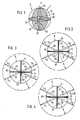
- the demultiplexer consists of a spherical optical collimator K.
- the sphere K is composed of eight identical spherical sectors, which are located in three mutually perpendicular separation planes T1, T2 and T3 (shown hatched) through the center of the sphere PO. are interconnected.
- FIG. 2 A view A of the intersection PA of the two separation planes T1 and T2 is in FIG. 2, a view B of the intersection PB of the two separation planes T1 and T3 in FIG. 3 and a view C of the intersection PC of the two separation planes T1 and T3 is shown in Fig. 4. These three FIGS. 2, 3 and 4 are intended to illustrate the functioning of the demodulator.
- the parting planes T1, T2, T3 between the spherical sectors are covered with reflection filter layers F1, F2, F3.
- the reflection filter layer F1, F2, F3 is adhered to the flat surfaces of the spherical sectors, which lie on one side of the dividing plane, and the spherical sectors lying on the opposite side of this dividing plane are by means of a the optically transparent cement K1, K2, K3 located in the reflection filter layer is connected to the other spherical sectors covered by the reflection filter layer.
- the refractive index of the optically transparent putty K1, K2, K3 should be approximately equal to the refractive index of the ball K.
- the beam paths S0 ... S7 shown in dashed lines in FIGS. 2 and 3 illustrate that within the kugelförmi gene collimator K the light propagates in parallel beams, and each parallel beam outside the collimator at a distance a from the center of the collimator to one Point is focused.
- all the optical elements that couple or couple out the light into the collimator K be it optical fibers, transmitting or receiving elements, are expediently arranged with their light entrance or exit surfaces.
- the reflection filter layers F1, F2, F3 are designed as edge filters or as bandpass filters in such a way that from one entering the ball K, PO at its center GE directed light beam S0 with light components of the wavelengths ⁇ 1 ...
- the partial beam S1 of the wavelength ⁇ 1 is reflected on the filter F3 and passes through the filters F1, F2, the partial beam S2 of the wavelength ⁇ 2 is reflected on the filters F2, F3 and the filter F1 passes, the partial beam S3 of the wavelength ⁇ 3 is reflected on the filters F1, F3 and the filter F2 passes, the partial beam S4 of the wavelength ⁇ 4 is reflected on the filter F2 and the filter F1, F2 passes, the partial beam S5 with the wavelength ⁇ 5 on the filter F2 is reflected and passes through the filters F1, F3, the partial beam S6 with the wavelength ⁇ 6 is reflected at the filter F1 and passes through the filters F2, F3 and the partial beam S7 with the wavelength ⁇ 7 passes through all filters F1, F2, F3.
- a multiplexer / demultiplexer for the combination or division of a few partial beams can also be implemented by a spherical collimator which has only one or two separation planes provided with reflection filter layers.
Landscapes
- Physics & Mathematics (AREA)
- General Physics & Mathematics (AREA)
- Optics & Photonics (AREA)
- Optical Couplings Of Light Guides (AREA)
Applications Claiming Priority (2)
| Application Number | Priority Date | Filing Date | Title |
|---|---|---|---|
| DE3634707 | 1986-10-11 | ||
| DE19863634707 DE3634707C1 (de) | 1986-10-11 | 1986-10-11 | Optischer Multiplexer/Demultiplexer |
Publications (1)
| Publication Number | Publication Date |
|---|---|
| EP0267380A1 true EP0267380A1 (fr) | 1988-05-18 |
Family
ID=6311555
Family Applications (1)
| Application Number | Title | Priority Date | Filing Date |
|---|---|---|---|
| EP87112536A Ceased EP0267380A1 (fr) | 1986-10-11 | 1987-08-28 | Multiplexeur/démultiplexeur optique |
Country Status (2)
| Country | Link |
|---|---|
| EP (1) | EP0267380A1 (fr) |
| DE (1) | DE3634707C1 (fr) |
Citations (4)
| Publication number | Priority date | Publication date | Assignee | Title |
|---|---|---|---|---|
| DE3324611A1 (de) * | 1983-07-08 | 1985-01-17 | Standard Elektrik Lorenz Ag, 7000 Stuttgart | Optische koppelanordnung |
| EP0146957A2 (fr) * | 1983-12-22 | 1985-07-03 | Alcatel N.V. | Multiplexeur/démultiplexeur optique |
| EP0158967A2 (fr) * | 1984-04-12 | 1985-10-23 | Alcatel SEL Aktiengesellschaft | Multiplexeur/démultiplexeur optique |
| EP0173930A2 (fr) * | 1984-09-01 | 1986-03-12 | Alcatel N.V. | Multiplexeur/démultiplexeur optique |
-
1986
- 1986-10-11 DE DE19863634707 patent/DE3634707C1/de not_active Expired
-
1987
- 1987-08-28 EP EP87112536A patent/EP0267380A1/fr not_active Ceased
Patent Citations (4)
| Publication number | Priority date | Publication date | Assignee | Title |
|---|---|---|---|---|
| DE3324611A1 (de) * | 1983-07-08 | 1985-01-17 | Standard Elektrik Lorenz Ag, 7000 Stuttgart | Optische koppelanordnung |
| EP0146957A2 (fr) * | 1983-12-22 | 1985-07-03 | Alcatel N.V. | Multiplexeur/démultiplexeur optique |
| EP0158967A2 (fr) * | 1984-04-12 | 1985-10-23 | Alcatel SEL Aktiengesellschaft | Multiplexeur/démultiplexeur optique |
| EP0173930A2 (fr) * | 1984-09-01 | 1986-03-12 | Alcatel N.V. | Multiplexeur/démultiplexeur optique |
Also Published As
| Publication number | Publication date |
|---|---|
| DE3634707C1 (de) | 1988-04-28 |
Similar Documents
| Publication | Publication Date | Title |
|---|---|---|
| DE3686234T2 (de) | Optisches strahlenteilerprisma. | |
| DE19737000B4 (de) | Lichtwellenlängen-Multiplexer/Demultiplexer | |
| DE3413703A1 (de) | Optischer multiplexer/demultiplexer | |
| EP0188764B1 (fr) | Arrangement optique avec un miroir ou réseau concave | |
| DE69800019T2 (de) | Verlustarmer Lichtwellenleiterkoppler | |
| EP0476384B1 (fr) | Réseau optique aux guides d'ondes comprenant une structure ramifiante avec plusieurs bouts arrangés cÔte à cÔte pour sortie d'ondes optiques | |
| DE69617778T2 (de) | Optischer Einfügungs- und Abtrennmultiplexer für optische Kommunikationsnetze | |
| DE3209928A1 (de) | Optischer multi/demultiplexer | |
| DE2910291A1 (de) | Bauelement mit optischen lichtwellenleitern | |
| DE3503203A1 (de) | Optischer multiplexer/demultiplexer | |
| DE3918726C1 (fr) | ||
| DE69901650T2 (de) | Optischer Mehrfachkoppler mit Linse | |
| DE3122781A1 (de) | "wellenlaengenmultiplexer bzw. wellenlaengendemultiplexer" | |
| DE2851625C2 (fr) | ||
| DE3008106C2 (fr) | ||
| DE102014115822A1 (de) | Ein optischer Multiplexer und Demultiplexer sowie ein Verfahren zum Herstellen und Zusammenbauen des Multiplexers/Demultiplexers | |
| EP0146196A2 (fr) | Elément constitutif de dispositif d'optique intégré | |
| DE60026771T2 (de) | Optisches Element zur Regelung der Strahlseparation von mehreren Strahlen | |
| WO2003012505A1 (fr) | Dispositif et procede pour multiplexer et/ou demultiplexer des signaux optiques de plusieurs longueurs d'onde | |
| EP0037007B1 (fr) | Procédé de fabrication d'un coupleur optique à 4 portes | |
| EP0267380A1 (fr) | Multiplexeur/démultiplexeur optique | |
| DE10225176C1 (de) | Vorrichtung zum Demultiplexen optischer Signale einer Vielzahl von Wellenlängen | |
| EP0146957A2 (fr) | Multiplexeur/démultiplexeur optique | |
| DE3229570A1 (de) | Optischer demultiplexer | |
| DE3218193C2 (de) | Opto-elektronische Schaltmatrix |
Legal Events
| Date | Code | Title | Description |
|---|---|---|---|
| PUAI | Public reference made under article 153(3) epc to a published international application that has entered the european phase |
Free format text: ORIGINAL CODE: 0009012 |
|
| AK | Designated contracting states |
Kind code of ref document: A1 Designated state(s): DE FR GB IT |
|
| 17P | Request for examination filed |
Effective date: 19880603 |
|
| 17Q | First examination report despatched |
Effective date: 19910226 |
|
| STAA | Information on the status of an ep patent application or granted ep patent |
Free format text: STATUS: THE APPLICATION HAS BEEN REFUSED |
|
| 18R | Application refused |
Effective date: 19910705 |
|
| RIN1 | Information on inventor provided before grant (corrected) |
Inventor name: HAUER, HEINER, DIPL.-ING. Inventor name: KUKE, ALBRECHT, DR.RER.NAT. |