EP0267687A1 - Dispositif de commande de soupape pour moteur à combustion interne - Google Patents
Dispositif de commande de soupape pour moteur à combustion interne Download PDFInfo
- Publication number
- EP0267687A1 EP0267687A1 EP87309026A EP87309026A EP0267687A1 EP 0267687 A1 EP0267687 A1 EP 0267687A1 EP 87309026 A EP87309026 A EP 87309026A EP 87309026 A EP87309026 A EP 87309026A EP 0267687 A1 EP0267687 A1 EP 0267687A1
- Authority
- EP
- European Patent Office
- Prior art keywords
- rocker arm
- oil pressure
- rocker
- cam
- driving system
- Prior art date
- Legal status (The legal status is an assumption and is not a legal conclusion. Google has not performed a legal analysis and makes no representation as to the accuracy of the status listed.)
- Granted
Links
- 238000002485 combustion reaction Methods 0.000 title claims abstract description 13
- 238000003825 pressing Methods 0.000 description 2
- 229910000838 Al alloy Inorganic materials 0.000 description 1
- 229910001018 Cast iron Inorganic materials 0.000 description 1
- 101100310856 Drosophila melanogaster spri gene Proteins 0.000 description 1
- 230000004323 axial length Effects 0.000 description 1
- 239000000919 ceramic Substances 0.000 description 1
- 230000003247 decreasing effect Effects 0.000 description 1
- 238000007599 discharging Methods 0.000 description 1
- 230000004048 modification Effects 0.000 description 1
- 238000012986 modification Methods 0.000 description 1
- 230000003014 reinforcing effect Effects 0.000 description 1
- 238000011144 upstream manufacturing Methods 0.000 description 1
Images

Classifications
-
- F—MECHANICAL ENGINEERING; LIGHTING; HEATING; WEAPONS; BLASTING
- F01—MACHINES OR ENGINES IN GENERAL; ENGINE PLANTS IN GENERAL; STEAM ENGINES
- F01L—CYCLICALLY OPERATING VALVES FOR MACHINES OR ENGINES
- F01L1/00—Valve-gear or valve arrangements, e.g. lift-valve gear
- F01L1/26—Valve-gear or valve arrangements, e.g. lift-valve gear characterised by the provision of two or more valves operated simultaneously by same transmitting-gear; peculiar to machines or engines with more than two lift-valves per cylinder
- F01L1/267—Valve-gear or valve arrangements, e.g. lift-valve gear characterised by the provision of two or more valves operated simultaneously by same transmitting-gear; peculiar to machines or engines with more than two lift-valves per cylinder with means for varying the timing or the lift of the valves
-
- F—MECHANICAL ENGINEERING; LIGHTING; HEATING; WEAPONS; BLASTING
- F02—COMBUSTION ENGINES; HOT-GAS OR COMBUSTION-PRODUCT ENGINE PLANTS
- F02F—CYLINDERS, PISTONS OR CASINGS, FOR COMBUSTION ENGINES; ARRANGEMENTS OF SEALINGS IN COMBUSTION ENGINES
- F02F1/00—Cylinders; Cylinder heads
- F02F1/24—Cylinder heads
- F02F1/42—Shape or arrangement of intake or exhaust channels in cylinder heads
- F02F1/4214—Shape or arrangement of intake or exhaust channels in cylinder heads specially adapted for four or more valves per cylinder
-
- F—MECHANICAL ENGINEERING; LIGHTING; HEATING; WEAPONS; BLASTING
- F02—COMBUSTION ENGINES; HOT-GAS OR COMBUSTION-PRODUCT ENGINE PLANTS
- F02F—CYLINDERS, PISTONS OR CASINGS, FOR COMBUSTION ENGINES; ARRANGEMENTS OF SEALINGS IN COMBUSTION ENGINES
- F02F1/00—Cylinders; Cylinder heads
- F02F1/24—Cylinder heads
- F02F2001/244—Arrangement of valve stems in cylinder heads
- F02F2001/245—Arrangement of valve stems in cylinder heads the valve stems being orientated at an angle with the cylinder axis
Definitions
- the present invention relates to a valve driving system for an internal combustion engine, and more particularly to such a valve driving system capable of selecting one of a plurality of cams for driving intake valves and/or exhaust valves in accordance with engine rpm.
- Unexamined Japanese Utility Model Publication No. 58605/1986 discloses a valve driving system for an internal combustion engine having two intake valves and two exhaust valves for each cylinder thereof.
- a first rocker arm pivotally mounted on a rocker shaft and engaged with the respective intake valves for driving them under low speed engine operating condition in accordance with the movement of a low speed cam having a cam lobe suitable for low speed engine operation and, on the side of the first rocker arm, a second rocker arm pivotally mounted on the rocker shaft for driving the respective intake valves by engagement with the first rocker arm under high speed engine operating condition in accordance with the movement of a high speed cam having a cam lobe suitable for high speed engine operation and an engaging means for engaging the second rocker arm with the first rocker arm under high engine rpm and releasing the engagement between the second rocker arm and the first rocker arm under low engine rpm.
- an identical valve driving mechanism is employed for the respective exhaust valves.
- valve driving system for an internal combustion engine in which two valves are provided for one or both of an intake port and an exhaust port in each cylinder, said valve driving system comprising cam shaft means formed with tw o types of cams of different shapes, one of which consists of a pair of low speed cams located at the end portion of said cam shaft means and the other of which consists of a high speed cam located at substantially the center part of said cam shaft means, a pair of first rocker arm means driven by said low speed cams respectively, each having a portion engaged with one of said valves, second rocker arm means driven by said high speed cam and located between said first rocker arm means, a pair of oil pressure chamber means formed in said second rocker arm means, a pair of plunger means each being provided in one of said oil pressure chamber means, a pair of bores each being formed engageably with one of said plunger means in one of said first rocker arm means, oil passage means formed in said second rocker arm means and communicated with said oil
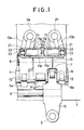
- FIG. 1 and 2 there is shown one cylinder of an internal combustion engine having a plurality of cylinders formed below a cylinder head 1 and each cylinder has two intake valves 2a and 2b for opening and shutting respective intake ports and one exhaust valve 3 for discharging exhaust gas from the cylinder.
- a camshaft 4 is provided between the intake valves 2a and 2b and the exhaust valve 3, and is formed with a pair of low speed cams 5a and 5b and a high speed cam 6.
- the high speed cam 6 is located at substantially the center portion between the low speed cams 5a and 5b.
- the high speed cam 6 has a cam lobe which is larger than the cam lobes in the low speed cams 5a and 5b so that the high speed cam 6 can provide greater cam lift and cam open period than the low speed cams 5a and 5b.
- a cam 7 for driving the exhaust valve 3 is provided between one of the low speed cams 5b and the high speed cam 6.
- first rocker shaft 8 on the side of the intake valves 2a and 2b with respect to the camshaft 4 and a second rocker shaft 9 on the side of the exhaust valve 3b with respect to the camshaft 4.
- first rocker arms 10a and 10b for driving the intake valves 2a and 2b respectively.
- the respective first rocker arms 10a and 10b are arranged so that they are engaged with the stem of the intake valves 2a, 2b at one end thereof and that they are engaged with the low speed cams 5a and 5b at the other end.
- a hydraulic lash adjustor 11 is provided at one end of each of the first rocker arms 10a and 10b so t hat the end of each of the first rocker arms 10a and 10b is engaged with the stem of one of the intake valves 2a and 2b without any lash between them and at the other end of each of the first rocker arms 10a and 10b, there is provided roller cam followers 12 for reducing sliding friction between the end of each of the first rocker arms 10a, 10b and one of the low speed cams 5a, 5b.
- An oil passage 18 is formed in the first rocker shaft 8 for feeding oil to the hydraulic lash adjustor 11 and an engaging device (explained later).
- the reference numeral 25 designates an oil passage communicated with the oil passage 18 for feeding oil to the hydraulic lash adjustors 11.
- a second rocker arm 13 for transmitting the movement of the high speed cam 6 to the respective first rocker arms 10a and 10b is pivotally mounted on the first rocker shaft 8 at substantially the center portion between the first rocker arms 10a and 10b and it is engaged with the high speed cam 6 at one end thereof.
- a spring 26 for pres sing the end of the second rocker arm 13 against the high speed cam 6 and preventing the second rocker arm 13 from hitting the high speed cam 6 at low engine rpm.
- a roller cam follower 14 At the end of the second rocker arm 13, there is provided a roller cam follower 14 for reducing sliding friction between the end of the second rocker arm 13 and the high speed cam 6.
- the axial length of the roller cam follower 14 is determined larger than that of the roller cam follower 12.
- a third rocker arm 15 for transmitting the movement of the cam 7 for driving the exhaust valve 3 to the exhaust valve 3 is pivotally mounted on the second rocker shaft 9 and at one end thereof, a roller cam follower 16 is provided for reducing sliding friction between the end of the third rocker arm 15 and the cam 7.
- Each of the engaging devices 17 comprises a cylinder bore 17a formed in the second rocker arm 13, a plunger 17b slidably received in the cylinder bore 17a and a oil pressure chamber 17c formed by the cylinder bore 17a and the plunger 17b.
- a wall 17d for separating the oil pressure chamber of one engaging device 17 from that of the other between the oil pressure chambers 17c of the respective engaging devices 17.
- An oil passage 17e for feeding oil to the respective oil pressure chambers 17c opens to the respective oil pressure chambers 17c at the wall 17d.
- the oil passage 17e is communicated with the oil passage 18 formed in the first rocker shaft 8. It is preferable that the oil passage 17e be formed by a drill so as to be oblique toward the upstream direction of the oil passage 18 , so that oil can be easily introduced into the oil pressure chamber 17c.
- Each of the oil pressure chamber 17c is communicated with an oil pump 19 through an oil passage 17e formed in the second rocker arm 13, the oil passage 4a formed in the rocker shaft 8 and an oil passage 18.
- Bores 21 for receiving the plunger 17b are formed in the respective first rocker arm 10a and 10b and plunger receivers 22 are provided in the respective bores 21 so that the respective plungers are maintained in abutting engagement with it.
- the opening of the valve 20 is reduced to reduce the amount of oil fed to the oil pressure chamber 17c and the oil pressure in the oil pressure chamber 17c becomes low, whereby the plunger 17b is forced to be moved outside of the bore 21 by the spring 23 and to be received by the wall 17d in the cylinder bore 17a and the second rocker arm 13 gets unengaged with the first rocker arms 10a and 10b.
- the valve opens the oil passage 18 and the oil pressure in the respective oil pressure chambers 17c is increased to become larger than pressure by the spring 23, whereby the respective plungers 17b get received in the bores 21 of the first rocker arms 10a and 10b and the second rocker arm 13 get engaged with the respective first rocker arms 10a and 10b.
- the second rocker arm 13 since the second rocker arm 13 is not engaged with the first rocker arms 10a and 10b at low engine rpm, the movement of the low speed cams 5a and 5b is transmitted to the intake valves 2a and 2b by the first rocker arms 10a and 10b and the intake valves 2a and 2b are driven by the low speed cams 5a and 5b, and, on the other hand, at high engine rpm, since the second rocker arm 13 is engaged with the first rocker arms 10a and 10b the movement of the high speed cam 6 is transmitted to the intake valves 2a and 2b through the second rocker arm 13 and the first rocker arms 10a and 10b and the intake valves 2a and 2b are driven by the high speed cam 6.
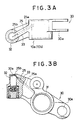
- the reference numeral 30 designates a fork portion for supporting the roller cam follower 12 and there is provided at the fork portion a bore 30a for engaging a shaft for supporting the roller cam follower 12. Further, there are provided a bore 31 in which the first rocker shaft 8 extends and a housing 32 for the hydraulic lash adjustor 11. A portion in the vicinity of the bore 31 and the housing 32 are connected by a reinforcing rib 33, extending substantially straight, in which the oil passage 25 for feeding oil to the hydraulic lash adjustor 11 is formed.
- the oil passage 25 consist of a bore 25a having large diameter and a bore 25b having small diameter and is formed by a drill so that the bore 25a is drilled from the side of the rocker shaft bore 31 and that the bore 25b is drilled from the side of the housing 32 through a reservoir chamber 32a, since it is difficult to form the oil passage 25 over the whole length by a drill having small diameter although it is preferable for effectively removing air from the reservoir chamber 32a that the diameter of the bore be small.
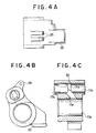
- Figures 4A to 4C show details of a second rocker arm 13 which is somewhat different from that used in the above described embodiment in the structure of the engaged portion with the high speed cam 6, although the basic structure is the same as that in the above described embodiment so that corresponding parts are designated by the same numerals as in the previous embodiment.
- the end of the second rocker arm is formed with a slipper 33 and is directly and slidably engaged with the high speed cam 6 in place of interposing the roller cam follower 14 between them in order to prevent the weight of the system from increasing, since the end portion of the second rocker arm 13 is engaged with the high speed cam 6 only at high rpm, while the end of each of the first rocker arms 10a and 10b is engaged under normal engine operating condition.
- the main body of the second rocker arm 13 is usually made of aluminum alloy but it is preferable to make the slipper 33 of special cast iron or ceramic for improving wear resistance.
- the oil passage 17e communicates with a bore 13a formed in the second rocker arm 13 for extending the rocker shaft 8 therein to the wall 17d for separating the respective oil pressure chambers 17c, and is formed by a drill so as to extend obliquely and upwardly toward the downstream direction of oil in order to make it easier to feed oil to the respective oil pressure chambers 17c and increase the oil pressure in the oil pressure chambers 17c to a predetermined pressure as soon as the valve 20 is opened. Further, there is provided a hole 34 for removing air from the respective oil pressure chambers 17c.
- the reference numeral 35 designates a supporting portion for securing the spri ng 26 for pressing the second rocker arm 13 against the high speed cam 6.
- the present invention can be applied to an engine having two intake valves and two exhaust valves.
- the intake valves are driven by the low speed cams or the high speed cam selectively in accordance with engine rpm in the above described embodiments, two exhaust valves can be driven in accordance with the present invention.
- oil passages 17e and 25 are communicated with the oil passage 8a in the above described embodiment, they can be independent passages for controlling the oil pressure in them independently. In such case, it is very advantageous to provide the oil passage 25 for feeding oil to the lash adjustor 11 in each of the first rocker arms 10a and 10b as shown in the above described embodiment.
Landscapes
- Engineering & Computer Science (AREA)
- Mechanical Engineering (AREA)
- General Engineering & Computer Science (AREA)
- Valve Device For Special Equipments (AREA)
- Valve-Gear Or Valve Arrangements (AREA)
Applications Claiming Priority (2)
| Application Number | Priority Date | Filing Date | Title |
|---|---|---|---|
| JP246084/86 | 1986-10-16 | ||
| JP61246084A JPH081125B2 (ja) | 1986-10-16 | 1986-10-16 | エンジンのバルブ駆動装置 |
Publications (2)
| Publication Number | Publication Date |
|---|---|
| EP0267687A1 true EP0267687A1 (fr) | 1988-05-18 |
| EP0267687B1 EP0267687B1 (fr) | 1992-01-02 |
Family
ID=17143247
Family Applications (1)
| Application Number | Title | Priority Date | Filing Date |
|---|---|---|---|
| EP87309026A Expired - Lifetime EP0267687B1 (fr) | 1986-10-16 | 1987-10-13 | Dispositif de commande de soupape pour moteur à combustion interne |
Country Status (4)
| Country | Link |
|---|---|
| US (2) | US4765289A (fr) |
| EP (1) | EP0267687B1 (fr) |
| JP (1) | JPH081125B2 (fr) |
| DE (1) | DE3775714D1 (fr) |
Cited By (10)
| Publication number | Priority date | Publication date | Assignee | Title |
|---|---|---|---|---|
| GB2196694B (en) * | 1986-10-23 | 1990-09-26 | Honda Motor Co Ltd | Variable valve operation device in internal combustion engine |
| EP0416628A1 (fr) * | 1989-09-08 | 1991-03-13 | Nissan Motor Co., Ltd. | Disposition de culbuteurs pour système de commande de soupapes variable |
| FR2653164A1 (fr) * | 1989-10-12 | 1991-04-19 | Nissan Motor | Agencement de culbuteur pour train de soupapes d'un moteur a combustion interne du type a reglage variable des soupapes. |
| GB2238353A (en) * | 1989-11-22 | 1991-05-29 | Fuji Heavy Ind Ltd | I.c.engine valve mechanism |
| EP0576768A1 (fr) * | 1992-06-27 | 1994-01-05 | Mercedes-Benz Ag | Dispositif de commande de soupapes pour moteur à combustion interne multicylindre |
| EP0601250A1 (fr) * | 1991-09-04 | 1994-06-15 | Honda Giken Kogyo Kabushiki Kaisha | Dispositif de commande de soupapes pour moteur à combustion interne |
| US5345898A (en) * | 1992-08-29 | 1994-09-13 | Dr. Ing. H.C.F. Porsche Ag | Valve operating mechanism for an internal-combustion engine |
| US5456226A (en) * | 1994-02-15 | 1995-10-10 | Mercedes Benz Ag | Method of minimizing play in a valve operating mechanism |
| EP0913557A3 (fr) * | 1997-10-29 | 2000-05-03 | Honda Giken Kogyo Kabushiki Kaisha | Dispositif de commande de soupape dans un moteur à combustion interne |
| EP2540996A3 (fr) * | 2011-06-27 | 2013-11-27 | Kwang Yang Motor Co., Ltd. | Structure d'élément de commande de soupape variable de moteur |
Families Citing this family (17)
| Publication number | Priority date | Publication date | Assignee | Title |
|---|---|---|---|---|
| US4887563A (en) * | 1986-10-16 | 1989-12-19 | Honda Giken Kogyo Kabushiki Kaisha | Valve operating apparatus for an internal combustion engine |
| CA1323533C (fr) * | 1987-12-28 | 1993-10-26 | Toshihiro Oikawa | Systeme de soupapes pour moteurs a combustion interne |
| JPH01178710A (ja) * | 1988-01-06 | 1989-07-14 | Mazda Motor Corp | エンジンのバルブ駆動装置 |
| JPH0621575B2 (ja) * | 1988-04-13 | 1994-03-23 | 本田技研工業株式会社 | 内燃機関の動弁制御方法 |
| JP2517078Y2 (ja) * | 1990-04-13 | 1996-11-13 | 本田技研工業株式会社 | 内燃機関の動弁装置 |
| USD342955S (en) | 1992-07-24 | 1994-01-04 | Bankier Companies | Vacuum manifold |
| JP2809005B2 (ja) * | 1992-09-17 | 1998-10-08 | 日産自動車株式会社 | 内燃機関の可変動弁装置 |
| DE19756018A1 (de) | 1997-12-17 | 1999-06-24 | Porsche Ag | Einrichtung zur Druck- und/oder Schmiermittelbeaufschlagung eines hydraulischen Verbrauchers in einer Brennkraftmaschine |
| EP1232336A4 (fr) * | 1999-09-17 | 2009-08-05 | Diesel Engine Retarders Inc | Accumulateur a volume captif pour systeme a perte de mouvement |
| JP4248131B2 (ja) * | 2000-07-05 | 2009-04-02 | ヤマハ発動機株式会社 | 4サイクルエンジンの動弁装置 |
| DE10155828A1 (de) * | 2001-11-14 | 2003-05-22 | Ina Schaeffler Kg | Schlepphebel eines Ventiltriebs einer Brennkraftmaschine |
| US6871622B2 (en) | 2002-10-18 | 2005-03-29 | Maclean-Fogg Company | Leakdown plunger |
| US7128034B2 (en) | 2002-10-18 | 2006-10-31 | Maclean-Fogg Company | Valve lifter body |
| US7273026B2 (en) | 2002-10-18 | 2007-09-25 | Maclean-Fogg Company | Roller follower body |
| US7028654B2 (en) | 2002-10-18 | 2006-04-18 | The Maclean-Fogg Company | Metering socket |
| US7191745B2 (en) | 2002-10-18 | 2007-03-20 | Maclean-Fogg Company | Valve operating assembly |
| TW201144574A (en) * | 2010-06-15 | 2011-12-16 | Kwang Yang Motor Co | Structure of driving member of engine valve |
Citations (2)
| Publication number | Priority date | Publication date | Assignee | Title |
|---|---|---|---|---|
| GB2162245A (en) * | 1984-07-24 | 1986-01-29 | Honda Motor Co Ltd | Controlling ic engine valve opening |
| EP0213758A1 (fr) * | 1985-07-31 | 1987-03-11 | Honda Giken Kogyo Kabushiki Kaisha | Mécanisme de fonctionnement de soupape |
Family Cites Families (10)
| Publication number | Priority date | Publication date | Assignee | Title |
|---|---|---|---|---|
| US4534323A (en) * | 1982-12-23 | 1985-08-13 | Nissan Motor Co., Ltd. | Valve operation changing system of internal combustion engine |
| JPS6119911A (ja) * | 1984-07-06 | 1986-01-28 | Honda Motor Co Ltd | 内燃機関の動弁装置 |
| JPS6158605A (ja) * | 1984-08-30 | 1986-03-25 | フィグラ株式会社 | 化粧料塗布具 |
| DE3613912A1 (de) * | 1985-04-26 | 1986-10-30 | Mazda Motor Corp., Hiroshima | Variabler ventilmechanismus fuer verbrennungsmotoren |
| DE3613945A1 (de) * | 1985-04-26 | 1986-10-30 | Mazda Motor Corp., Hiroshima | Veraenderbarer ventilmechanismus fuer verbrennungsmaschinen |
| JPS62121811A (ja) * | 1985-07-31 | 1987-06-03 | Honda Motor Co Ltd | 内燃機関の動弁装置 |
| EP0276533B1 (fr) * | 1986-07-30 | 1993-09-22 | Honda Giken Kogyo Kabushiki Kaisha | Mécanisme de fonctionnement de soupape pour moteur à combustion interne |
| CA1308977C (fr) * | 1986-08-27 | 1992-10-20 | Tsuneo Konno | Mecanisme d'actionnement des soupapes de moteur a combustion interne |
| US4793296A (en) * | 1987-01-30 | 1988-12-27 | Honda Giken Kogyo Kabushiki Kaisha | Valve operating mechanism for internal combustion engine |
| DE3780617T2 (de) * | 1987-01-30 | 1992-12-10 | Honda Motor Co Ltd | Ventilantriebmechanismus fuer brennkraftmaschine. |
-
1986
- 1986-10-16 JP JP61246084A patent/JPH081125B2/ja not_active Expired - Lifetime
-
1987
- 1987-10-07 US US07/105,730 patent/US4765289A/en not_active Ceased
- 1987-10-13 EP EP87309026A patent/EP0267687B1/fr not_active Expired - Lifetime
- 1987-10-13 DE DE8787309026T patent/DE3775714D1/de not_active Expired - Fee Related
-
1990
- 1990-08-22 US US07/570,917 patent/USRE34596E/en not_active Expired - Lifetime
Patent Citations (2)
| Publication number | Priority date | Publication date | Assignee | Title |
|---|---|---|---|---|
| GB2162245A (en) * | 1984-07-24 | 1986-01-29 | Honda Motor Co Ltd | Controlling ic engine valve opening |
| EP0213758A1 (fr) * | 1985-07-31 | 1987-03-11 | Honda Giken Kogyo Kabushiki Kaisha | Mécanisme de fonctionnement de soupape |
Non-Patent Citations (2)
| Title |
|---|
| PATENT ABSTRACTS OF JAPAN, vol. 10, no. 167 (M-488)[2223], 13th June 1986, & JP-A-61 19 911 (HONDA GIKEN KOGYO K.K.) 28-01-1986 * |
| PATENT ABSTRACTS OF JAPAN, vol. 10, no. 167 (M-488)[2223], 13th June 1986; & JP-A-61 19 912 (HONDA GIKEN KOGYO K.K.) 28-01-1986 * |
Cited By (12)
| Publication number | Priority date | Publication date | Assignee | Title |
|---|---|---|---|---|
| GB2196694B (en) * | 1986-10-23 | 1990-09-26 | Honda Motor Co Ltd | Variable valve operation device in internal combustion engine |
| EP0416628A1 (fr) * | 1989-09-08 | 1991-03-13 | Nissan Motor Co., Ltd. | Disposition de culbuteurs pour système de commande de soupapes variable |
| US5033420A (en) * | 1989-09-08 | 1991-07-23 | Nissan Motor Co., Ltd. | Rocker arm arrangement for variable timing type valve train |
| FR2653164A1 (fr) * | 1989-10-12 | 1991-04-19 | Nissan Motor | Agencement de culbuteur pour train de soupapes d'un moteur a combustion interne du type a reglage variable des soupapes. |
| GB2238353A (en) * | 1989-11-22 | 1991-05-29 | Fuji Heavy Ind Ltd | I.c.engine valve mechanism |
| GB2238353B (en) * | 1989-11-22 | 1994-02-16 | Fuji Heavy Ind Ltd | Valve mechanism for an internal combustion engine |
| EP0601250A1 (fr) * | 1991-09-04 | 1994-06-15 | Honda Giken Kogyo Kabushiki Kaisha | Dispositif de commande de soupapes pour moteur à combustion interne |
| EP0576768A1 (fr) * | 1992-06-27 | 1994-01-05 | Mercedes-Benz Ag | Dispositif de commande de soupapes pour moteur à combustion interne multicylindre |
| US5345898A (en) * | 1992-08-29 | 1994-09-13 | Dr. Ing. H.C.F. Porsche Ag | Valve operating mechanism for an internal-combustion engine |
| US5456226A (en) * | 1994-02-15 | 1995-10-10 | Mercedes Benz Ag | Method of minimizing play in a valve operating mechanism |
| EP0913557A3 (fr) * | 1997-10-29 | 2000-05-03 | Honda Giken Kogyo Kabushiki Kaisha | Dispositif de commande de soupape dans un moteur à combustion interne |
| EP2540996A3 (fr) * | 2011-06-27 | 2013-11-27 | Kwang Yang Motor Co., Ltd. | Structure d'élément de commande de soupape variable de moteur |
Also Published As
| Publication number | Publication date |
|---|---|
| USRE34596E (en) | 1994-05-03 |
| DE3775714D1 (de) | 1992-02-13 |
| US4765289A (en) | 1988-08-23 |
| EP0267687B1 (fr) | 1992-01-02 |
| JPS63100212A (ja) | 1988-05-02 |
| JPH081125B2 (ja) | 1996-01-10 |
Similar Documents
| Publication | Publication Date | Title |
|---|---|---|
| EP0267687B1 (fr) | Dispositif de commande de soupape pour moteur à combustion interne | |
| EP0420159B1 (fr) | Culbuteurs constituant un système de commande variable pour soupapes de moteur à combustion interne | |
| US4727831A (en) | Valve operating mechanism for internal combustion engine | |
| KR960007963B1 (ko) | 내연기관용 밸브제어수단 | |
| US6076492A (en) | Cylinder head for variable valve timing | |
| CA1284069C (fr) | Mecanisme de commande des soupapes d'un moteur a combustion interne | |
| US6343581B2 (en) | Variable valve timing and lift structure for four cycle engine | |
| EP0601250B1 (fr) | Dispositif de commande de soupapes pour moteur à combustion interne | |
| KR950014406B1 (ko) | 엔진의 밸브구동장치 | |
| EP0420139B1 (fr) | Moteur multisoupape | |
| EP0563574B1 (fr) | Dispositif de commande de soupape pour moteur à combustion interne | |
| US4881497A (en) | Valve operating system for internal combustion engine | |
| EP1462622B1 (fr) | Moteur à combustion interne à plusieurs cylindres | |
| GB2198787A (en) | I.C. engine valve timing control | |
| US6481398B2 (en) | High-low speed range switching type valve mechanism for internal combustion engine | |
| US4907550A (en) | Apparatus for changing operation timing of valves for internal combustion engine | |
| JPH0321726B2 (fr) | ||
| JPH04124417A (ja) | エンジンの潤滑装置 | |
| JPH0346642B2 (fr) | ||
| JPH0417706A (ja) | エンジンの弁作動装置 | |
| JP2580207B2 (ja) | エンジンの動弁装置 | |
| CA2110226A1 (fr) | Rattrapeur de jeu pour moteur a combustion interne | |
| JP2002081303A (ja) | エンジンのバルブ駆動装置 | |
| KR19980038560A (ko) | 로커암 타입 차량 엔진의 밸브 리프트량 조절 캠 구조 | |
| JP3200999B2 (ja) | 4サイクルエンジンの可変バルブタイミングリフト装置 |
Legal Events
| Date | Code | Title | Description |
|---|---|---|---|
| PUAI | Public reference made under article 153(3) epc to a published international application that has entered the european phase |
Free format text: ORIGINAL CODE: 0009012 |
|
| AK | Designated contracting states |
Kind code of ref document: A1 Designated state(s): DE FR GB |
|
| 17P | Request for examination filed |
Effective date: 19881110 |
|
| 17Q | First examination report despatched |
Effective date: 19890831 |
|
| GRAA | (expected) grant |
Free format text: ORIGINAL CODE: 0009210 |
|
| AK | Designated contracting states |
Kind code of ref document: B1 Designated state(s): DE FR GB |
|
| REF | Corresponds to: |
Ref document number: 3775714 Country of ref document: DE Date of ref document: 19920213 |
|
| ET | Fr: translation filed | ||
| PLBE | No opposition filed within time limit |
Free format text: ORIGINAL CODE: 0009261 |
|
| STAA | Information on the status of an ep patent application or granted ep patent |
Free format text: STATUS: NO OPPOSITION FILED WITHIN TIME LIMIT |
|
| 26N | No opposition filed | ||
| REG | Reference to a national code |
Ref country code: GB Ref legal event code: IF02 |
|
| PGFP | Annual fee paid to national office [announced via postgrant information from national office to epo] |
Ref country code: FR Payment date: 20031003 Year of fee payment: 17 |
|
| PGFP | Annual fee paid to national office [announced via postgrant information from national office to epo] |
Ref country code: GB Payment date: 20031008 Year of fee payment: 17 |
|
| PGFP | Annual fee paid to national office [announced via postgrant information from national office to epo] |
Ref country code: DE Payment date: 20041007 Year of fee payment: 18 |
|
| PG25 | Lapsed in a contracting state [announced via postgrant information from national office to epo] |
Ref country code: GB Free format text: LAPSE BECAUSE OF NON-PAYMENT OF DUE FEES Effective date: 20041013 |
|
| GBPC | Gb: european patent ceased through non-payment of renewal fee |
Effective date: 20041013 |
|
| PG25 | Lapsed in a contracting state [announced via postgrant information from national office to epo] |
Ref country code: FR Free format text: LAPSE BECAUSE OF NON-PAYMENT OF DUE FEES Effective date: 20050630 |
|
| REG | Reference to a national code |
Ref country code: FR Ref legal event code: ST |
|
| PG25 | Lapsed in a contracting state [announced via postgrant information from national office to epo] |
Ref country code: DE Free format text: LAPSE BECAUSE OF NON-PAYMENT OF DUE FEES Effective date: 20060503 |