EP0267772A2 - Echangeur de chaleur et son procédé de fabrication - Google Patents
Echangeur de chaleur et son procédé de fabrication Download PDFInfo
- Publication number
- EP0267772A2 EP0267772A2 EP87309904A EP87309904A EP0267772A2 EP 0267772 A2 EP0267772 A2 EP 0267772A2 EP 87309904 A EP87309904 A EP 87309904A EP 87309904 A EP87309904 A EP 87309904A EP 0267772 A2 EP0267772 A2 EP 0267772A2
- Authority
- EP
- European Patent Office
- Prior art keywords
- heat exchanger
- fins
- generally
- cooling
- gas
- Prior art date
- Legal status (The legal status is an assumption and is not a legal conclusion. Google has not performed a legal analysis and makes no representation as to the accuracy of the status listed.)
- Granted
Links
Images


Classifications
-
- H—ELECTRICITY
- H10—SEMICONDUCTOR DEVICES; ELECTRIC SOLID-STATE DEVICES NOT OTHERWISE PROVIDED FOR
- H10W—GENERIC PACKAGES, INTERCONNECTIONS, CONNECTORS OR OTHER CONSTRUCTIONAL DETAILS OF DEVICES COVERED BY CLASS H10
- H10W40/00—Arrangements for thermal protection or thermal control
- H10W40/40—Arrangements for thermal protection or thermal control involving heat exchange by flowing fluids
- H10W40/43—Arrangements for thermal protection or thermal control involving heat exchange by flowing fluids by flowing gases, e.g. forced air cooling
-
- H—ELECTRICITY
- H10—SEMICONDUCTOR DEVICES; ELECTRIC SOLID-STATE DEVICES NOT OTHERWISE PROVIDED FOR
- H10W—GENERIC PACKAGES, INTERCONNECTIONS, CONNECTORS OR OTHER CONSTRUCTIONAL DETAILS OF DEVICES COVERED BY CLASS H10
- H10W40/00—Arrangements for thermal protection or thermal control
- H10W40/20—Arrangements for cooling
- H10W40/22—Arrangements for cooling characterised by their shape, e.g. having conical or cylindrical projections
- H10W40/226—Arrangements for cooling characterised by their shape, e.g. having conical or cylindrical projections characterised by projecting parts, e.g. fins to increase surface area
Definitions
- This invention relates to a heat exchanger and to methods of making the same. While useful in various applications, heat exchangers in accordance with the present invention are particularly useful for cooling electronic components.
- a heat exchanger for cooling or heating an object, which heat exchanger comprises a plurality of spaced apart substantially parallel thermally conductive fins characterized in that diverting means are provided which, when a gas is introduced in one direction into said heat exchanger diverts at least part of said gas in a second direction generally perpendicular to said one direction.
- said diverting means are arranged to divert said gas in mutually opposite directions generally perpendicular to said one direction.
- the fins are of generally triangular cross-section and are arranged so that alternate fins face in opposite directions and the longest side of the fins comprise said diverting means.
- said fins are of generally right-angled triangular cross-section.
- the longest side of said fins is curved.
- a tip of at least some of said fins is folded back on to itself.
- the diverting means comprises a generally triangular spacer member disposed between adjacent fins.
- the fins are of generally rectangular cross-section.
- said generally triangular spacer member comprises a base and two concave sides which converge towards an apex of said substantially triangular spacer member.
- the longest side of said generally triangular spacer member may be curved.
- said fins and said diverting means are integrally formed.
- the fins are of generally parallelogram shape.
- Heat exchangers in accordance with the present invention preferably include an end plate disposed at each end thereof.
- the present invention also provides an electronic assembly comprising a plurality of components, characterised in that at least some of said components have heat exchangers in accordance with the invention mounted thereon, and wherein ducting is arranged to direct, in use, cooling gas into said heat exchangers.
- said fins are right-angled triangles.
- said method includes the step of folding at least some of the free tips of said fins back upon said fins.
- the present invention also provides a method of making another embodiment of a heat exchanger in accordance with the invention, which method comprises the steps of forming a generally parallelogram shaped piece of thermally conductive material and folding said material to form a 'V' shape member defining two fins.
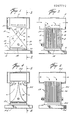
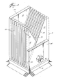
- reference numeral 10 generally indicates a heat exchanger which is attached to integrated circuit chip 12 which in turn is mounted on a substrate 14.
- the heat exchange 10 receives a cooling gas such as air from a duct 16 which is arranged to conduct the cooling gas to one of more heat exchangers 10 although the flow of cooling gas through the heat exchanger 10 may be reversed if desired.
- the heat exchanger 10 comprises a plurality of thin flat substantially parallel thermally conductive cooling fins 18 and 20.
- the cooling fins 18 and 20 may be of any suitable thermal conductive materials such as copper, aluminium, berylium oxide or aluminum oxide. Aluminum is presently preferred in view of its low density.
- Preferably the cooling fins 18 and 20 are identical for ease of manufacture.
- Each of the cooling fins 18 and 20 includes a bottom 22, a first side 24, a second side 26 and a tip 29.
- the cooling fins 18 and 20 are in the shape of right angle triangles and have an aspect ratio greater than 1:0, i.e., the first side 24 is longer than the bottom 22.
- the second side 26 may be curved or circular, i.e., similar to the shapes shown in Figs. 11, 12, 15 and 16.
- Alternate cooling fins 18, 20 are reversed so as to face in opposite directions to provide a multiplicity of gas passageways 30 between adjacent fins 18 and between adjacent fins 20.
- cooling gas enters the heat exchanger 10 downwardly through inlet 28.
- the cooling gas is then diverted by the second side 26 of the cooling fins 18, 20 and leaves the heat exchanger 10 substantially horizontally through gas passageways 30.
- each of the cooling fins 18 and 20 are folded over or alternately dipped in, for example epoxy, to maintain the cooling fins in spaced juxtaposition and to form an edge.
- each of the cooling fins 18 and 20 may be 0.127 mm (5 mils) thick and the heat exchanger 10 may comprise eighty fins for a 10.16 mm ⁇ 10.16 mm (400 ⁇ 400 mil) area heat exchanger with a height of 17.78 mm (700 mils).
- the thickness and exact dimensions of the heat exchanger 10 can be varied in order to optimize the heat exchange and to minimize the air flow resistance.
- the embodiment being described has a modular feature of increasing the number of fins as the size of the base increases. This feature allows the heat exchanger to be sized proportionally to the surface to be cooled which is also approximately proportional to the amount of the heat to be disipated in many applications.
- an end plate 34 is provided at each end of the plurality of cooling fins 18 and 20 and is connected to the duct 16 for directing the cooling gas through the gas passageways 30.
- end plates 34 and cooling fins 18 and 20 may be secured together with any suitable securing means such as a bolt 36. Alternatively, the assembly can be soldered together.
- a thermal conductive base 38 is connected to the bottom 22 of the cooling fins 18 and 20 and the bottom surface thereof may be attached to the chip 12 by any suitable means, for example, the bottom surface may be machined to an accurate finish and soldered to the chip 12.
- Alternatives include the use of microcapillary attachment through the use of microcapillaries provided on the underside of the thermally conductive base 38 or the back of the chip 12.
- the heat exchanger 10 can be pressed against the back of the chip 12 for simple pressure contact and thermal conducting greases can also be used. In short, all methods of attachment ensuring low thermal impedance can be used.
- Conventional systems use a compliant or conformable interface in multi-chip applications where the surfaces of the chips do not form a planar surface (a common problem). The preferred embodiments do not require a compliant interface since the heat exchanger 10 may be directly mounted on the chip 12.
- the cooling air flowing through the gas passageways 30 produces a lower pressure drop than conventional systems and hence the gas moving system required can be less powerful.
- the average velocity of the air through the gas passageways 30 is reduced. This reduces restrictions to flow at both the inlet and the outlet of the passageways 30 and hence the acoustic noise generated.
- the structure shown in Figs. 1 to 3 has provided adequate cooling for components running at 30 W with only a gas pressure of 76.2 mm (3 inches) of water required at an air flow rate of about 57 litres per minute.
- a thermal resistance of 1.7° centigrade per watt was achieved for a heat sink base of 0.66 square centimetres consisting of 46 fins each 0.178 mm (7 mils) wide and spaced (0.178 mm) 7 mils apart with a height of 1.2 cm. This performance is equivalent to about 1.2° centigrade temperature rise per watt of power dissipated per square centimetre, a remarkable achievement for such a simple, low cost air cooled heat exchanger.
- the heat exchanger 10 will provide excellent performance as an air cooler.
- the heat exchanger 10 At an operating pressure of 25.4 cm (10 inches of water) and an air flow of about 2.83 l/s (6 cfm) the heat exchanger 10 itself offers a thermal resistance of less than 0.6 K/W. This corresponds to a temperature rise of only 30 K for a 50 W chip, which would then add to the intrinsic temperature rise of about 10 K to yield a 40° temperature rise of the heat producing junctions on a chip over ambient.
- the efficiency of a triangular cooling fin such as 18 and 20 is greater than that of a standard rectangular fin.
- the air viscosity reduces the flow rate drastically and increases caloric resistance; for wider gas passageways 30 the reduced fin surface area as well as the increased boundary layer thickness increases the convective heat transfer resistance.
- the optimum fin thickness may be 0.254 mm (10 mils) and in such cases with an applied air pressure of 25.4 mm (1 inch) of water the total thermal resistance of the heat exchanger is predicted to be 1.5 K/W with an air flow rate of 0.94 l/s (2.0 cfm).
- Figs. 7, 8, 9 and 10 a modified version of the heat exchanger and a method of manufacturing the same are shown.
- a sheet of thermal conductive material 40 such as copper is provided, in which one or more cutters 42 cut the sheet into a plurality of right-angled triangle shaped cooling fins 18 a and 20 a with the adjacent fins 18 a and 20 a being connected adjacent their bottoms 22 a by a connection 44.
- the tips 29 a are folded over and back towards the bottoms 22 a and the adjacent fins 18 a and 20 a are folded along the connections 44 towards each other in a direction whereby adjacent fins 18 a and 20 a are reversed relative to one another to form a heat exchanger 10 a as shown in Fig. 10 which then may be suitably connected to a chip 12 a and receives a cooling gas from a duct 16 a and function similarly to that described in connection with Figs. 1 to 3.
- heat exchanger 10 b which is made out of an integral piece of thermally conductive material in which fins 18 b and 20 b are formed therein by utilizing a circular saw blade 50 to create oppositely directed fins having a circular side 26 b to provide oppositely directed air outlet passageways.
- the fins are generally rectangular.
- FIG. 13 and 14 another embodiment 10 c of a heat exchanger is shown in which the cooling fins 18 c and 20 c are manufactured out of a solid piece of material by the use of a heating element 54 which by movement in a series of parallel alternating paths at opposite sides of the heat exchanger 10 c creates an integral heat exchanger 10 c having similar characteristics to those of Figs. 7 to 11 by providing right-angled triangular shapes facing in reversing directions and interconnected at their edges.
- the heat exchangers described can be made in a variety of materials. It may be desirable to match the thermal expansion to the chip 12 d and the heat exchanger 10 d of Figs. 4, 5 and 6 with a suitable material, such as silicon or molybdenum.
- the heat exchanger 10 d of Figs. 4, 5 and 6 may be constructed of a plurality of copper clad tapes or printed circuit board like material where the insulated material is patterned and removed by, for example, etching.
- the copper provides the heat exchanger and the insulator, for example, polyimide or board material, provides for ducting of the incoming cooling gas. The gas flows through the heat exchanger 10 d in a laminar fashion.
- such a process provides a plurality of side-by-side parallel positioned and spaced rectangularly shaped copper cooling fins 56 and spacer means 58 positioned between and in the middle of adjacent cooling fins 56.
- the top of the heat exchanger 10 b is connected to an air duct 16 b and the spacer means 58 includes first 60 and second 62 passageways extending from the top of the fins to opposite sides of the heat exchanger 10 d .
- the passageways 60 and 62 are curved from the top of the fins downwardly into a horizontal direction for directing the cooling air away from the chip 12 d .
- FIGs. 15 and 16 a modification is provided in which the cooling fins 18 e and 20 e are substituted in Figs. 1 to 3 for cooling fins 18 and 20.
- This embodiment is a minor variation of Figs. 1 to 3 in that the only difference is that the sides 26 e are now curved and in this case made circular.
- This structure provides for a somewhat smoother gas flow transition from the inlet to the outlet direction and hence provides a still lower pressure drop and less turbulence and noise.
- This particular embodiment also uses somewhat less materials which reduces cost and weight and has less fin overlap at the bottom of the heat exchanger. Such a structure will reduce the conduction resistance through the bottom part a little and thus should provide a slightly better performance for a given size.
- the foregoing embodiments provide very efficient, compact and low cost heat exchangers which enable the removal of more power than previously thought possible with air cooling.
- the noise generation and high pressure requirements for the air mover were undesirable in some applications.
- FIG. 17 and 18 Another embodiment of a heat exchanger in accordance with the present invention is shown in Figs. 17 and 18 in which the cooling fins 18 f and 20 f are parallelogram shaped.
- Each parallelogram includes a bottom, top and two sides which extend upwardly and outwardly from the bottom. For example, the sides may be inclined at approximately 45° relative to the bottom.
- the heat exchanger 10 f incorporates the excellent cooling performance of the earlier embodiments by utilizing a multitude of thin fins 18 f and 20 f . However, in order to lower the pressure requirements, the heat exchanger 10 f is not as compact as the heat exchanger 10 of Figs. 1 to 3.
- the parallelogram shaped cooling fins 18 f and 20 f have a greater surface area than the fins 18 and 20 of Figs.
- the gas passageways in the embodiment 10 f are preferably twice as wide as the thickness of the fins.
- This additional gas passage area provides an increased inlet and outlet cross-sectional areas for the air flow. This decreases the air velocity substantially and hence reduces the amount of noise generated.
- the cooling fins 18 f and 20 f may be formed by any suitable manufacturing method as previously described. One suitable method is cutting the desired thickness of thermal conductive material such as copper into double sized fins, that is, a fin which is twice the combined length of the fins 18 f and 20 f . The double size fin is then folded in the middle to form the two fins 18 f and 20 f with a space in between the cooling fins 18 f and 20 f . Suitable spacers may be provided to maintain the gas passageways. It will be appreciated that the ends of the heat exchanger 10f are provided with end plates similar to end plates 34.
- the heat exchanger 10 f will still allow approximately 25% substrate coverage by semi-conductor components.
- the thermal resistance of the arrangement was found to be 1.7°C/W at an air flow of 0.94 l/s (2 cfm) and at a pressure of 6.35 mm (0.25 inches) of water.
- the heated exhaust air from any heat exchanger does not materially affect any other heat exchanger.
- the heat exchanger volume of the heat exchanger 10 of Figs. 1 to 3 is less than 1 cubic centimetre. Utilizing the heat exchanger 10 in an array, up to 33% substrate coverage by chips has been achieved without a performance degradation.
- the heat exchangers 10 f of Figs. 17 and 18 offer a similar thermal performance but at a much reduced pressure requirement. The pressure requirements of the heat exchangers of 10 f have been reduced by sacrificing compactness, thereby resulting in a somewhat bigger heat exchanger of about 3 cubic centimetre which limits the substrate coverage to about 25%.
- the heat exchanger 10 f has the same modular advantage as the heat exchanger 10 can be scaled to smaller or larger chip power heat dissipation by removing or adding fin pairs. Additionally, like the heat exchanger 10, the heat exchanger 10 f may be connected to each chip without requiring a conventional compliant interface, which is a rather poorly conducting media, between the chips and the heat exchangers where the heat flux densities are highest.
- the various embodiments described above generally employ the basic ideas of using a plurality of thin fins and narrow gas cooling passageways which extend between the top of the heat sink and lateral ends between both sides of the heat sink.
- the advantages of these structures lie in using the same structure to both duct the gas normally to the inlet direction while providing heat transfer at the same time.
- Each of the different embodiments has advantages of its own and different versions may be preferred for different applications.
Landscapes
- Cooling Or The Like Of Electrical Apparatus (AREA)
- Heat-Exchange Devices With Radiators And Conduit Assemblies (AREA)
- Cooling Or The Like Of Semiconductors Or Solid State Devices (AREA)
Applications Claiming Priority (4)
| Application Number | Priority Date | Filing Date | Title |
|---|---|---|---|
| GB8626826 | 1986-11-10 | ||
| GB868626826A GB8626826D0 (en) | 1986-11-10 | 1986-11-10 | Microlaminar air cooled heat sink |
| US07/092,255 US4777560A (en) | 1987-09-02 | 1987-09-02 | Gas heat exchanger |
| US92255 | 1987-09-02 |
Publications (3)
| Publication Number | Publication Date |
|---|---|
| EP0267772A2 true EP0267772A2 (fr) | 1988-05-18 |
| EP0267772A3 EP0267772A3 (en) | 1989-02-22 |
| EP0267772B1 EP0267772B1 (fr) | 1993-01-13 |
Family
ID=26291528
Family Applications (1)
| Application Number | Title | Priority Date | Filing Date |
|---|---|---|---|
| EP87309904A Expired - Lifetime EP0267772B1 (fr) | 1986-11-10 | 1987-11-09 | Echangeur de chaleur et son procédé de fabrication |
Country Status (3)
| Country | Link |
|---|---|
| EP (1) | EP0267772B1 (fr) |
| JP (1) | JPH0783194B2 (fr) |
| DE (1) | DE3783571T2 (fr) |
Cited By (3)
| Publication number | Priority date | Publication date | Assignee | Title |
|---|---|---|---|---|
| EP0564027A1 (fr) * | 1992-03-31 | 1993-10-06 | Akzo Nobel N.V. | Echangeur de chaleur, procédé de sa fabrication et des applications |
| FR2703443A1 (fr) * | 1993-03-30 | 1994-10-07 | Thermalloy Inc | Procédé et appareil de dissipation d'énergie thermique. |
| EP1290928A4 (fr) * | 2001-03-03 | 2004-07-28 | Zalman Tech Co Ltd | Dissipateur thermique et dispositif a dissipateur thermique comportant ledit dissipateur thermique |
Families Citing this family (3)
| Publication number | Priority date | Publication date | Assignee | Title |
|---|---|---|---|---|
| DE102010063074B3 (de) * | 2010-12-14 | 2012-04-12 | INSTITUT FüR MIKROTECHNIK MAINZ GMBH | Mikrofluidisches Bauteil, Reaktor aus mehreren solchen Bauteilen und Verfahren zu deren Herstellung |
| JP6096642B2 (ja) * | 2013-10-31 | 2017-03-15 | 株式会社ティラド | 熱交換器用フィンおよびそれを用いたヒートシンク、熱交換器用フィンの製造方法 |
| JP6855873B2 (ja) * | 2017-03-27 | 2021-04-07 | 富士電機株式会社 | 鉄道車両用電力変換装置 |
Family Cites Families (2)
| Publication number | Priority date | Publication date | Assignee | Title |
|---|---|---|---|---|
| JPS54139354U (fr) * | 1978-03-21 | 1979-09-27 | ||
| ES2724451T3 (es) * | 2010-02-04 | 2019-09-11 | Univ Pennsylvania | ICOS regula fundamentalmente la expansión y la función de linfocitos Th17 humanos inflamatorios |
-
1987
- 1987-11-09 DE DE8787309904T patent/DE3783571T2/de not_active Expired - Fee Related
- 1987-11-09 EP EP87309904A patent/EP0267772B1/fr not_active Expired - Lifetime
- 1987-11-10 JP JP62285134A patent/JPH0783194B2/ja not_active Expired - Lifetime
Cited By (4)
| Publication number | Priority date | Publication date | Assignee | Title |
|---|---|---|---|---|
| EP0564027A1 (fr) * | 1992-03-31 | 1993-10-06 | Akzo Nobel N.V. | Echangeur de chaleur, procédé de sa fabrication et des applications |
| US5353867A (en) * | 1992-03-31 | 1994-10-11 | Akzo Nobel Nv | Heat exchanger, a method of manufacturing same, and applications |
| FR2703443A1 (fr) * | 1993-03-30 | 1994-10-07 | Thermalloy Inc | Procédé et appareil de dissipation d'énergie thermique. |
| EP1290928A4 (fr) * | 2001-03-03 | 2004-07-28 | Zalman Tech Co Ltd | Dissipateur thermique et dispositif a dissipateur thermique comportant ledit dissipateur thermique |
Also Published As
| Publication number | Publication date |
|---|---|
| JPH0783194B2 (ja) | 1995-09-06 |
| DE3783571T2 (de) | 1993-07-15 |
| DE3783571D1 (de) | 1993-02-25 |
| JPS63232399A (ja) | 1988-09-28 |
| EP0267772B1 (fr) | 1993-01-13 |
| EP0267772A3 (en) | 1989-02-22 |
Similar Documents
| Publication | Publication Date | Title |
|---|---|---|
| US4777560A (en) | Gas heat exchanger | |
| US5020586A (en) | Air-cooled heat exchanger for electronic circuit modules | |
| EP0285779B1 (fr) | Système de refroidissement pour modules de dispositifs à semi-conducteurs | |
| US6223814B1 (en) | Flexible foil finned heatsink structure and method of making same | |
| JP3278809B2 (ja) | 折りたたみ式ひれ状のヒートシンク及びそれを用いた熱交換器 | |
| US4884631A (en) | Forced air heat sink apparatus | |
| US5304846A (en) | Narrow channel finned heat sinking for cooling high power electronic components | |
| US5653285A (en) | Heat sink apparatus | |
| US6942025B2 (en) | Uniform heat dissipating and cooling heat sink | |
| US6855880B2 (en) | Modular thermoelectric couple and stack | |
| US5294831A (en) | Circuit pack layout with improved dissipation of heat produced by high power electronic components | |
| JPH06244328A (ja) | ヒートシンク | |
| US6830097B2 (en) | Combination tower and serpentine fin heat sink device | |
| EP0253126B1 (fr) | Puits thermique | |
| US4833766A (en) | Method of making gas heat exchanger | |
| US5673177A (en) | Heat sink structure with corrugated wound wire heat conductive elements | |
| JPH03263382A (ja) | 熱電変換装置 | |
| EP0267772A2 (fr) | Echangeur de chaleur et son procédé de fabrication | |
| JPH10125836A (ja) | ヒートシンク冷却装置 | |
| JP3434552B2 (ja) | ヒートシンク | |
| JPS6256788A (ja) | 熱交換装置 | |
| JPH05283878A (ja) | 熱放散特性に優れたヒートシンク冷却フィンおよびその製造法 | |
| CN216980543U (zh) | 一种单管功率器件的双面冷却散热结构 | |
| CN118160087A (zh) | 用于冷却功率电子器件的能流体穿流的冷却器的冷却肋布置结构 | |
| JPH02130878A (ja) | 熱電装置 |
Legal Events
| Date | Code | Title | Description |
|---|---|---|---|
| PUAI | Public reference made under article 153(3) epc to a published international application that has entered the european phase |
Free format text: ORIGINAL CODE: 0009012 |
|
| AK | Designated contracting states |
Kind code of ref document: A2 Designated state(s): DE FR GB IT SE |
|
| PUAL | Search report despatched |
Free format text: ORIGINAL CODE: 0009013 |
|
| AK | Designated contracting states |
Kind code of ref document: A3 Designated state(s): DE FR GB IT SE |
|
| 17P | Request for examination filed |
Effective date: 19890512 |
|
| 17Q | First examination report despatched |
Effective date: 19910710 |
|
| GRAA | (expected) grant |
Free format text: ORIGINAL CODE: 0009210 |
|
| AK | Designated contracting states |
Kind code of ref document: B1 Designated state(s): DE FR GB IT SE |
|
| PG25 | Lapsed in a contracting state [announced via postgrant information from national office to epo] |
Ref country code: IT Free format text: LAPSE BECAUSE OF FAILURE TO SUBMIT A TRANSLATION OF THE DESCRIPTION OR TO PAY THE FEE WITHIN THE PRESCRIBED TIME-LIMIT;WARNING: LAPSES OF ITALIAN PATENTS WITH EFFECTIVE DATE BEFORE 2007 MAY HAVE OCCURRED AT ANY TIME BEFORE 2007. THE CORRECT EFFECTIVE DATE MAY BE DIFFERENT FROM THE ONE RECORDED. Effective date: 19930113 Ref country code: SE Effective date: 19930113 |
|
| REF | Corresponds to: |
Ref document number: 3783571 Country of ref document: DE Date of ref document: 19930225 |
|
| ET | Fr: translation filed | ||
| PLBE | No opposition filed within time limit |
Free format text: ORIGINAL CODE: 0009261 |
|
| STAA | Information on the status of an ep patent application or granted ep patent |
Free format text: STATUS: NO OPPOSITION FILED WITHIN TIME LIMIT |
|
| 26N | No opposition filed | ||
| PGFP | Annual fee paid to national office [announced via postgrant information from national office to epo] |
Ref country code: GB Payment date: 19940908 Year of fee payment: 8 |
|
| PGFP | Annual fee paid to national office [announced via postgrant information from national office to epo] |
Ref country code: DE Payment date: 19940916 Year of fee payment: 8 Ref country code: FR Payment date: 19940916 Year of fee payment: 8 |
|
| PG25 | Lapsed in a contracting state [announced via postgrant information from national office to epo] |
Ref country code: GB Effective date: 19951109 |
|
| GBPC | Gb: european patent ceased through non-payment of renewal fee |
Effective date: 19951109 |
|
| PG25 | Lapsed in a contracting state [announced via postgrant information from national office to epo] |
Ref country code: FR Effective date: 19960731 |
|
| PG25 | Lapsed in a contracting state [announced via postgrant information from national office to epo] |
Ref country code: DE Effective date: 19960903 |
|
| REG | Reference to a national code |
Ref country code: FR Ref legal event code: ST |