EP0267777A2 - Contrôle de moteur bipolaire - Google Patents
Contrôle de moteur bipolaire Download PDFInfo
- Publication number
- EP0267777A2 EP0267777A2 EP87309924A EP87309924A EP0267777A2 EP 0267777 A2 EP0267777 A2 EP 0267777A2 EP 87309924 A EP87309924 A EP 87309924A EP 87309924 A EP87309924 A EP 87309924A EP 0267777 A2 EP0267777 A2 EP 0267777A2
- Authority
- EP
- European Patent Office
- Prior art keywords
- servo
- data
- track
- motor
- centerline
- Prior art date
- Legal status (The legal status is an assumption and is not a legal conclusion. Google has not performed a legal analysis and makes no representation as to the accuracy of the status listed.)
- Granted
Links
Images



Classifications
-
- G—PHYSICS
- G11—INFORMATION STORAGE
- G11B—INFORMATION STORAGE BASED ON RELATIVE MOVEMENT BETWEEN RECORD CARRIER AND TRANSDUCER
- G11B21/00—Head arrangements not specific to the method of recording or reproducing
- G11B21/02—Driving or moving of heads
- G11B21/08—Track changing or selecting during transducing operation
-
- G—PHYSICS
- G11—INFORMATION STORAGE
- G11B—INFORMATION STORAGE BASED ON RELATIVE MOVEMENT BETWEEN RECORD CARRIER AND TRANSDUCER
- G11B5/00—Recording by magnetisation or demagnetisation of a record carrier; Reproducing by magnetic means; Record carriers therefor
- G11B5/48—Disposition or mounting of heads or head supports relative to record carriers ; arrangements of heads, e.g. for scanning the record carrier to increase the relative speed
- G11B5/54—Disposition or mounting of heads or head supports relative to record carriers ; arrangements of heads, e.g. for scanning the record carrier to increase the relative speed with provision for moving the head into or out of its operative position or across tracks
- G11B5/55—Track change, selection or acquisition by displacement of the head
- G11B5/5521—Track change, selection or acquisition by displacement of the head across disk tracks
- G11B5/5526—Control therefor; circuits, track configurations or relative disposition of servo-information transducers and servo-information tracks for control thereof
- G11B5/553—Details
Definitions
- This invention pertains to a servo control system for use in a magnetic disc storage device, and more particularly one that utilizes a novel arrangement of control stepper motor windings to position a data head relative to a data track on the disc, and to position the data head over the track centerline on the disc.
- Disc storage devices are used in data processing systems for storing relatively large amounts of information that can generally be accessed in milliseconds.
- a typical storage device comprises a rotating magnetizable disc medium having several surfaces, in the form of an assembly of one or more stacked platters, on which data is magnetically sensed and/or recorded in addressable sectors located on circular data track centerlines.
- the disc assembly is mounted on a drive spindle in the storage device that rotates at a constant high speed.
- the storage device also includes one or more transducers or read/write heads, associated with each surface of the disc. The transducers are mounted in spaced relation on an arm of a movable transducer carriage.
- the servo controller actuates the carriage in a controlled fashion to move all the data heads in unison radially over the disc surfaces to position any one of the data heads over a selected track centerline. Since all the data heads on the carriage move together, the device also includes control circuitry that selects one of the read/write heads to perform a data transfer operation.
- the servo controller responds to commands from the data processing system.
- the controller does this by transforming those commands into an analog servo signal which ultimately drives, usually through a power amplifier, an eletromechanical actuator that connects to the transducer carriage.
- the disc device operates in one of two modes.
- the first (usually open-loop) is a mode in which the carriage, and thus the selected data head, is driven to the vicinity of the desired circular track centerline. Once that data head reaches that vicinity, the system is switched to a track following (or closed-loop, servo controlled) mode.
- the position of the actuator or carriage is servo controlled to cause the center of the selected data head to align itself with the centerline of the data track.
- servo systems typically employ formatting information prerecorded on the data disc to allow the controller to detect the displacement between the data head and the track centerline.
- a format might include servo data that is continuously prerecorded along servo tracks on a dedicated surface of the disc assembly (dedicated servo data) together with servo data prerecorded in circumferentially spaced servo sectors interspersed, or embedded between adjacent pairs of storage data sectors on a data surface of the disc assembly (embedded servo data).
- Dedicated servo data is typically read by a read-only servo head, while embedded servo data is read along with the data by a read/write head, and thereafter separated from the data by servo data processing circuitry.
- the servo data from both the dedicated and data surfaces is decoded by the disc controller, thereby enabling it to modify a servo control signal, if necessary, and thus continuously maintain the position of the data head in alignment with the selected data track centerline.
- the disc controller thereby enabling it to modify a servo control signal, if necessary, and thus continuously maintain the position of the data head in alignment with the selected data track centerline.
- several factors limit the alignment accuracy and thus, the maximum attainable data track density, of a disc storage device. The most common of these factors stem from electrical and mechanical disturbances, or noise.
- DC bias forces and electrical offsets are examples of some disturbances.
- a notable mechanical disturbance is spindle runout, or wobble, which is the difference between the actual centerline of a track and the effective centerline presented to a head positioned a fixed distance from the mounting center of the disc.
- Control system lag is another factor that effects positioning accuracy.
- Lag is the time delay between the time the controller detects an off-track condition and the time the actuator begins to move the transducer into alignment with the data track centerline. Some of this delay is attributable to the electrical response characteristics of the servo control system, as, for example, resulting from a low sampling rate; the remaining delay is attributable to the mechanical response characteristics of the electromechanical actuator.
- Such delays characterize the band width of the servo control system. The greater the band width, the faster the positioning system can respond to an off-track condition, thereby providing tightly controlled positioning of the data head.
- a positioning system having high band width provides increased data track density because centerlines can be followed within a smaller tolerance. There are other factors that contribute to misalignment during track following operations.
- Conventional methods of increasing servo band width include increasing the frequency of structural mechanical resonances, providing continuous position feedback from a dedicated servo surface, and providing a higher sample rate position feedback emanating from the data surfaces.
- a number of approaches have been disclosed for improving head alignment electronically.
- One approach has been to provide sectorized, or embedded, servo positioning data on the data storage track, as an alternative to or in supplement to servo positioning information on a dedicated disc surface.
- this approach does not overcome band width limitations.
- Another approach has been to use a transducer positioned at a radially fixed stationary reference point over a position reference track on the rotating disc to detect misposition error signals.
- this also does not provide an optimum result, because it lacks face compensation, noise reduction, or a close fixed relationship to the peculiarities of positioning of the actual track being read.
- Another approach has been to provide first and second sets of servo signals on a data surface recorded in alternate track locations at centerlines shifted radially by the width of one half track with respect to the centerlines of the storage data tracks.
- the approach to using this information is to make several passes over the information and store a set of misposition error signals so that the correction signals can be utilized during subsequent read/write operations.
- This system must use considerable processing hardware and memory space for storing the information.
- it is incapable of dynamically correcting for modifications that may occur during the use of the system.
- An objective of this invention is to provide an improved control circuit for a stepping motor having multiple windings used in a disc drive.
- Another objective herein is to provide a control circuit for a stepper motor which allows a large number of steps per electrical revolution, but requiring only a minimum number of drive transistors, stepper motor leads, or series resistors.
- Another objective is to provide an improved servo control system capable of providing a large number of servo bursts with every revolution of the disc, so that fine positioning of the read/write transducer over the center of the data track is available with every movement of the transducer carriage.
- Another objective herein is to provide a servo system compatible with a track seeking system that uses a course seek of the stepper motor to the center of the track to be read, after which a closed loop servo data scheme takes control to accurately position the head exactly over the center of the data track.
- this invention comprises a multiple winding bipolar drive, comprising, in a preferred form, 10 windings coupled in series pairs to form a five-winding star configuration, one end of each pair of windings being connected at a common centerpoint. The other ends of the windings are connected between a pair of bipolar transistors which are selectively energized so that either four or five phases are always turned on.
- a multiple winding bipolar drive comprising, in a preferred form, 10 windings coupled in series pairs to form a five-winding star configuration, one end of each pair of windings being connected at a common centerpoint.
- the other ends of the windings are connected between a pair of bipolar transistors which are selectively energized so that either four or five phases are always turned on.
- servo bursts are recorded in sectors spaced around the disc.
- the odd and even servo bursts as well as a sync burst are recorded in each sector, with the sync burst being recorded on the centerline and the odd and even burst being recorded one-half step on either side of the data track which is to be the centerline of the read/write data track.
- the read/write transducer can be accurately positioned over the track to be read by first performing a coarse seek using an open loop control to carry the carriage and transducer head to approximately the position of the track desired, and then using a closed loop control responsive first to detection of the sync burst and then to the odd/even servo burst to center the read/write head exactly over the center of the data track to be read.
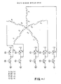
- this shows a 10-phase motor having windings or stator coils A-E, each formed of two windings connected in series.
- windings A1 and A2 are connected in series to form stator coil A, and so on.
- the coils are star connected at a common junction point 12. Leads 14 at the opposite end of each pair of windings are lead out to control transistors 16-26.
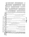
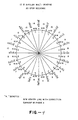
- a rotor (not shown) carries a diametrically magnetized permanent magnet having poles N and S. As the windings are energized in accordance with the diagram shown in FIG 3, the magnetic field of the stator is rotated, causing rotation of the rotor. The rotor seeks to realign itself with each new position of the magnetic vector formed by the selective energization of the stator coils. The switching pattern that causes the magnetic field to move and the rotor to rotate, is shown in FIG 3. The net result of this sequence of energization is to produce a 20-step vector diagram as illustrated in FIG 2. The phase positions are achieved using a half-step scheme of four phases on, then five phases on, then four phases, repeating this over 360 electrical degrees. The result is to produce 20 steps of the stepper motor for each 360 electrical degrees.
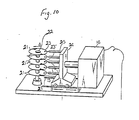
- FIG 10 is a schematic illustration of the type of disc drive the present motor and servo control system might use.
- the reference number 21 refers to discs for storing data.
- the stack of discs 21 is fixed on a rotating shaft 22 rotated in the direction of arrow A by an electric motor (not shown) at a constant high speed.
- a plurality of transducers 23 are provided cooperating with the disc to read and write data on the tracks on the discs.
- the transducers 23 are supported by a carriage 24 by means of arms 25, the transducers being moved by the carriage 24 forward and backward in the direction of the arrows B and B ⁇ . Accordingly, the transducers 23 travel in a radial direction relative to and slightly above the corresponding magnetic discs 21. This movement of the transducers is accomplished by a motor of the type described in FIG 1 under control of signals applied through the bipolar transistors 16-25 shown at the bottom of FIG 1.
- the voltages at the input points of the stator windings A, B, C, D, E have different polarities with respect to one another.
- the rotor is driven by an electrical field that rotates in a predetermined direction.
- the rotor will rotate through 20 separate steps in the manner shown, to step the transducers from track to track across the surface of the disc. It can be seen by reviewing the sequence listed under PHASES ON that the current applied through only one coil at a time is changed by the control circuit, thereby alternating five or four phases on.
- transistor 24 is connected to a positive voltage source VM.
- This positive voltage is connected through a coil A, and then must flow out through another coil to ground.
- transistor 24 would be turned on to connect the positive motor voltage to coil A and transistor 17 would be turned on to complete a circuit through coil B to ground.
- both coils A and B are energized.
- These transistors 16-25 are energized according to the table shown in FIG 3 using sequencer logic shown in FIG 8 implemented in a manner which is well known to a person of skill in this technology.
- transistor 24 would be off
- transistor 25 would be on to connect coil A to ground
- transistor 16 would be on to connect coil B to + voltage
- transistor 17 would be off
- transistor 18 would be on to connect coil C to plus voltage
- transistor 19 would be off
- transistor 20 would be off
- transistor 21 would be on to connect coil D to ground
- transistor 22 would be on to connect coil E to + voltage
- transistor 23 would be off. It should also be noted that this is a five-phase on position whereas, in the next adjacent track 14F, the only change made is that transistor 18 is turned off so that now only four phases are on and the rotor moves to the next track position.
- the prime difference between reaching track 13F and 14F is that to reach track 14F, coil C has no current flow.
- FIG 2 represents one sequence of 360 electrical degrees (not mechanical degrees) for the motor.
- the motor repeats this electrical sequence every 360 electrical degrees or, in this case every 20 steps.
- the motor actually makes 1,060 steps across the surface of the disc. Therefore, the pattern in FIG 2 repeats 53 times in moving the transducer read/write head completely across the surface of the disc.
- FIG 2 is the electrical angle plot showing the phases energized to reach tracks 0F through 19F. Having reached track 19F, the next track would be 20F, reached by energizing the same phases as used to reach track 0F, and then the sequence would continue up to 1,060.
- servo information is read from the two adjoining servo tracks on either side of the read/write track so that by operating on this servo data, contemporaneously with the actual positioning of the transducer head over the track, a highly exact positioning of the read/write head over the center of the data track can be achieved.
- the 1/2 coil current is applied under the control of a digital to analog converter (DAC) as shown in the coil energization sequence spelled out in FIG 5.
- DAC digital to analog converter
- This figure differs from FIG 3 in that it can be seen that under the list of phases on, one phase is always shown as not receiving full current.
- This coil receiving a servo-signal-modulated 1/2 current accurately positions the read/write head over the data track.
- the present scheme achieves much of its accuracy because of the fact that the stepper motor detent positions are highly accurate.
- the head can be moved with great accuracy to a position where the servo bursts being read from two successive motor detent positions are exactly balanced. If the opposite approach were taken, and the read/write positions coincided with the stepper motor detent positions, then the servo data would have to be written on either side of those detent positions, which is extremely difficult to accurately accomplish on a repetitive basis.
- a further significant achievement of this invention is that it achieves 20 steps per electrical revolution, although using only 10 drive transistors, as shown in FIG 1, and only five stepper motor leads and five series resistors, one to each node.
- the control circuit for this invention which is now to be explained in detail, is dramatically simplified from that appearing in prior motor control circuits.
- the general arrangement of servo data on one of the data discs 21 appears in FIG 6, and in greater detail in FIG 7.
- the ODD 40 and EVEN 42 servo bursts are recorded on detent positions reached by turning on either four or five coils in the motor.
- the SYNC bursts are recorded on the centerlines 44 where the data is read and recorded. It can be seen from FIG 6 that a number of servo sectors (in this preferred embodiment 16 in number) are recorded in regularly spaced circumferential positions on the surface of each data disc. Each of these servo sectors has alternating ODD and EVEN servo bursts recorded on the motor detent positions and SYNC bursts recorded on the read/write centerlines.
- These servo bursts 40, 42 are each 80 microseconds long and consist of a SYNC burst, ODD burst and EVEN burst.
- the coils are sequentially energized according to the format shown in FIG 3, using a course seeking mode to one of the detent positions, and then a closed loop servo control positioning of the head exactly over the center of a data track.
- 16 of these servo sectors containing odd/even and synchro data are recorded around the circumference of each data disc 21.
- the read/write head can continuously read the odd/even servo bursts and operate on this information to exactly position the head over the center of the read/write track by modulation of the half current signal applied to the unenergized coil.
- the details of the control circuit used to position the stepper motor by driving the coils are shown in FIG 8 with the output stages which actually drive the coil with the modulated or half current to position the head in response to the servo signal, shown in Fig 9.
- the sequencer logic 50 is programmed simply to follow the format set forth in FIG 5, in response to the four control signals received from a controlling microprocessor on lines 52, 54, 56, 58 to apply either 12 volts or ground to the base of each of transistors 60-25, and thereby apply the appropriate voltages to each of the five coils.
- the result of this arrangement is that to achieve final positioning of a transducer over a read/write track, either 12 volts or ground is being applied to four of the five phases A, B, C, D, E, with a modulated half current signal being applied through a driver circuit to the fifth coil.
- the TRACK FOLLOW signal changes state and the odd/even servo bursts 40, 42 are read by the read/write amp and demodulator 60 of FIG 8, and added to the half track DC offset signal at summer 62.
- the direction of the offset is established at inverter 64 by a control signal on line 66 from the sequencer logic 50.
- the coil to which the signal is to be applied is defined by one of the control signals AOS-EOS appearing on lines 67, 68, 69, 70, or 71 to control the switches 72.
- the voltage applied to a selected one of the coils as the output from demodulator 60 plus the DC track offset which is carried to the coil through line 74 accounts for the fact that the actual read/write centerline at which the head is to be positioned must be reached by balancing the odd/even servo data.
- the servo signal being generated on line 73 only needs to account for the small deviation from the exact half track center between the two motor detent positions, and not for the full one-half track offset from the next adjacent motor detent.
- the servo logic 80 is controlled by the system clock 82 to detect when the head has completed its course seek to roughly the position between the two motor detent position which define the opposite sides of the read/write track centerline.
- the read/write amplifier 60 via coils 84 looks for the SYNC burst 86 which is recorded on the center of each read/write track centerline.
- the servo logic 80 opens gate line 90, 91 to activate a standard circuit within the read/write amplifier modulator 60 which can detect the odd/even servo burst 40, 42 and generate a signal through amplifier 93, which represents the offset necessary to modulate the standard half track DC offset at summer 62 to provide an accurate positioning signal to the appropriate coil on line 74.
- the output on line 73 represents the difference in amplitude between the ODD and EVEN servo bursts 40, 42 as the 16 servo sectors 50 continuously rotate past the read/write transducer head.
- the output on line 73 from the read/write demodulator is 0. If there is any offset from the read/write track centerline, then a positive or negative voltage representing that offset appears on line 73.
- the output signal on line 73 would be balanced.
- the servo signal would be created on line 73 to drive the head back toward the center position. It should also be noted and can be discovered from a close review of FIG 5 that the signal is always applied to a phase that is not receiving any other signal as an output from the sequencer logic. Thus, if the head has been moved to a detent position defined by having four phases on, the output on line 74 is simply coupled to the fifth phase. However, if the head was moved to a detent position defined by five phases, then one phase is shut off as far as receiving a signal output from the sequencer logic, and then receives a signal on line 74.
- the seeking from the motor detent position to the actual track center line occurs when the TRACK FOLLOW signal on line 58 goes low, closing the switch 95 in line 73, and also causing the appropriate one of the switches 72 to be closed to apply the modulated half track DC offset signal to be applied to one coil.
- the stage A shown in FIG 9 is to show the signals that normally drive the coils as taken from transistors Q4 and Q8. In the normal operation of track seeking, these two transistors override the op amp 101 that appears on the left-hand side of the stage.
- transistors Q4 and Q8 are shut off, and the control signal indicated as the signal to coil A now becomes the output from the operational amplifier 101.
Landscapes
- Moving Of The Head To Find And Align With The Track (AREA)
- Control Of Electric Motors In General (AREA)
- Control Of Motors That Do Not Use Commutators (AREA)
- Moving Of Head For Track Selection And Changing (AREA)
- Control Of Stepping Motors (AREA)
- Valve Device For Special Equipments (AREA)
Priority Applications (1)
| Application Number | Priority Date | Filing Date | Title |
|---|---|---|---|
| AT87309924T ATE84630T1 (de) | 1986-11-10 | 1987-11-10 | Kontrolle fuer bipolaren motor. |
Applications Claiming Priority (2)
| Application Number | Priority Date | Filing Date | Title |
|---|---|---|---|
| US92955986A | 1986-11-10 | 1986-11-10 | |
| US929559 | 1986-11-10 |
Publications (3)
| Publication Number | Publication Date |
|---|---|
| EP0267777A2 true EP0267777A2 (fr) | 1988-05-18 |
| EP0267777A3 EP0267777A3 (en) | 1989-01-04 |
| EP0267777B1 EP0267777B1 (fr) | 1993-01-13 |
Family
ID=25458048
Family Applications (1)
| Application Number | Title | Priority Date | Filing Date |
|---|---|---|---|
| EP87309924A Expired - Lifetime EP0267777B1 (fr) | 1986-11-10 | 1987-11-10 | Contrôle de moteur bipolaire |
Country Status (7)
| Country | Link |
|---|---|
| EP (1) | EP0267777B1 (fr) |
| JP (1) | JP2559774B2 (fr) |
| KR (1) | KR960005416B1 (fr) |
| AT (1) | ATE84630T1 (fr) |
| AU (1) | AU597537B2 (fr) |
| DE (1) | DE3783572T2 (fr) |
| HK (1) | HK111693A (fr) |
Families Citing this family (2)
| Publication number | Priority date | Publication date | Assignee | Title |
|---|---|---|---|---|
| JP2867378B2 (ja) * | 1992-05-14 | 1999-03-08 | マイコム 株式会社 | 4相ステッピングモータの駆動装置及び4相ステッピングモータ |
| US6768977B1 (en) * | 1999-11-30 | 2004-07-27 | Texas Instruments Incorporated | Method and circuit for modeling a voice coil actuator of a mass data storage device |
Family Cites Families (3)
| Publication number | Priority date | Publication date | Assignee | Title |
|---|---|---|---|---|
| US3562725A (en) * | 1968-10-15 | 1971-02-09 | Sperry Rand Corp | Coarse and fine positioning of magnetic read heads |
| US4530020A (en) * | 1984-06-06 | 1985-07-16 | Dma Systems | Self-timed runout correction pattern |
| IT1182420B (it) * | 1985-02-08 | 1987-10-05 | Olivetti & Co Spa | Apparecchiatura per registrare e leggere informazioni su un disco magnetico |
-
1987
- 1987-11-09 AU AU80915/87A patent/AU597537B2/en not_active Ceased
- 1987-11-10 JP JP62284087A patent/JP2559774B2/ja not_active Expired - Lifetime
- 1987-11-10 KR KR1019870012635A patent/KR960005416B1/ko not_active Expired - Fee Related
- 1987-11-10 DE DE8787309924T patent/DE3783572T2/de not_active Expired - Fee Related
- 1987-11-10 AT AT87309924T patent/ATE84630T1/de not_active IP Right Cessation
- 1987-11-10 EP EP87309924A patent/EP0267777B1/fr not_active Expired - Lifetime
-
1993
- 1993-10-21 HK HK1116/93A patent/HK111693A/en not_active IP Right Cessation
Also Published As
| Publication number | Publication date |
|---|---|
| HK111693A (en) | 1993-10-29 |
| DE3783572D1 (de) | 1993-02-25 |
| KR960005416B1 (ko) | 1996-04-24 |
| KR880006681A (ko) | 1988-07-23 |
| EP0267777B1 (fr) | 1993-01-13 |
| ATE84630T1 (de) | 1993-01-15 |
| JP2559774B2 (ja) | 1996-12-04 |
| JPS63225977A (ja) | 1988-09-20 |
| EP0267777A3 (en) | 1989-01-04 |
| DE3783572T2 (de) | 1993-07-29 |
| AU597537B2 (en) | 1990-05-31 |
| AU8091587A (en) | 1988-05-12 |
Similar Documents
| Publication | Publication Date | Title |
|---|---|---|
| US4739239A (en) | Bipolar motor control | |
| US5808440A (en) | Hybrid communication method and apparatus for a three-phase brushless DC motor | |
| US4775902A (en) | Apparatus for recording and reading information on a magnetic disk with track following circuitry | |
| US4638384A (en) | Head positioning mechanism for rotating disk data storage system | |
| GB2125186A (en) | Precision alignment system for information storage devices | |
| JPH02183477A (ja) | デイスクドライブシステム | |
| US4819095A (en) | Method of controlling a disk head position by individually timing zones servo information | |
| US4812929A (en) | Head positioning mechanism for rotating disk data storage system | |
| US6219197B1 (en) | Method and apparatus for servo positioning in a direct access storage device with a transducer read element width greater than ⅓ and less than ½ width of a data cylinder | |
| US5208523A (en) | Stepper motor with vernier control mode | |
| US4636884A (en) | Head positioning control system in magnetic disk device of index servo system | |
| EP0267777A2 (fr) | Contrôle de moteur bipolaire | |
| US20240062785A1 (en) | Dual spindle motors and dual spindle motor control for data storage | |
| JP2532250B2 (ja) | ディスクドライブのサ―ボゲイン補償方法 | |
| US5914581A (en) | Information recording device | |
| US12125500B2 (en) | Maintaining consistent location for spindle interrupts when spindle motor switches modes | |
| US12198722B2 (en) | Enhancing spin up and spin down times for data storage devices | |
| JPS61271675A (ja) | 磁気ヘツドの位置決めサ−ボ装置 | |
| JPH06189515A (ja) | スピンドルモータ | |
| JP2521270B2 (ja) | 磁気ヘツドの位置決め方法 | |
| JPH02292783A (ja) | 磁気ヘッド位置決め制御方法 | |
| JPH01124168A (ja) | デイスク装置 | |
| JPS58121182A (ja) | 磁気デイスク装置のサ−ボ信号書込み方式 | |
| JPS61242381A (ja) | スピンドルモ−タの回転速度制御装置 | |
| JPS62267976A (ja) | 磁気デイスク装置 |
Legal Events
| Date | Code | Title | Description |
|---|---|---|---|
| PUAI | Public reference made under article 153(3) epc to a published international application that has entered the european phase |
Free format text: ORIGINAL CODE: 0009012 |
|
| AK | Designated contracting states |
Kind code of ref document: A2 Designated state(s): AT BE CH DE ES FR GB GR IT LI LU NL SE |
|
| PUAL | Search report despatched |
Free format text: ORIGINAL CODE: 0009013 |
|
| AK | Designated contracting states |
Kind code of ref document: A3 Designated state(s): AT BE CH DE ES FR GB GR IT LI LU NL SE |
|
| 17P | Request for examination filed |
Effective date: 19890414 |
|
| 17Q | First examination report despatched |
Effective date: 19901130 |
|
| GRAA | (expected) grant |
Free format text: ORIGINAL CODE: 0009210 |
|
| AK | Designated contracting states |
Kind code of ref document: B1 Designated state(s): AT BE CH DE ES FR GB GR IT LI LU NL SE |
|
| PG25 | Lapsed in a contracting state [announced via postgrant information from national office to epo] |
Ref country code: NL Effective date: 19930113 Ref country code: GR Free format text: LAPSE BECAUSE OF FAILURE TO SUBMIT A TRANSLATION OF THE DESCRIPTION OR TO PAY THE FEE WITHIN THE PRESCRIBED TIME-LIMIT Effective date: 19930113 Ref country code: BE Effective date: 19930113 Ref country code: AT Effective date: 19930113 |
|
| REF | Corresponds to: |
Ref document number: 84630 Country of ref document: AT Date of ref document: 19930115 Kind code of ref document: T |
|
| REF | Corresponds to: |
Ref document number: 3783572 Country of ref document: DE Date of ref document: 19930225 |
|
| ET | Fr: translation filed | ||
| ITF | It: translation for a ep patent filed | ||
| PG25 | Lapsed in a contracting state [announced via postgrant information from national office to epo] |
Ref country code: ES Free format text: LAPSE BECAUSE OF FAILURE TO SUBMIT A TRANSLATION OF THE DESCRIPTION OR TO PAY THE FEE WITHIN THE PRESCRIBED TIME-LIMIT Effective date: 19930424 |
|
| NLV1 | Nl: lapsed or annulled due to failure to fulfill the requirements of art. 29p and 29m of the patents act | ||
| PG25 | Lapsed in a contracting state [announced via postgrant information from national office to epo] |
Ref country code: SE Effective date: 19931111 |
|
| PLBE | No opposition filed within time limit |
Free format text: ORIGINAL CODE: 0009261 |
|
| STAA | Information on the status of an ep patent application or granted ep patent |
Free format text: STATUS: NO OPPOSITION FILED WITHIN TIME LIMIT |
|
| PG25 | Lapsed in a contracting state [announced via postgrant information from national office to epo] |
Ref country code: LU Free format text: LAPSE BECAUSE OF NON-PAYMENT OF DUE FEES Effective date: 19931130 Ref country code: LI Effective date: 19931130 Ref country code: CH Effective date: 19931130 |
|
| 26N | No opposition filed | ||
| REG | Reference to a national code |
Ref country code: CH Ref legal event code: PL |
|
| EUG | Se: european patent has lapsed |
Ref document number: 87309924.6 Effective date: 19940610 |
|
| REG | Reference to a national code |
Ref country code: GB Ref legal event code: 732E |
|
| ITPR | It: changes in ownership of a european patent |
Owner name: CESSIONE;SEAGATE TECHNOLOGY INTERNATIONAL |
|
| REG | Reference to a national code |
Ref country code: FR Ref legal event code: TP |
|
| PGFP | Annual fee paid to national office [announced via postgrant information from national office to epo] |
Ref country code: FR Payment date: 19961023 Year of fee payment: 10 |
|
| PG25 | Lapsed in a contracting state [announced via postgrant information from national office to epo] |
Ref country code: FR Free format text: THE PATENT HAS BEEN ANNULLED BY A DECISION OF A NATIONAL AUTHORITY Effective date: 19971130 |
|
| REG | Reference to a national code |
Ref country code: FR Ref legal event code: ST |
|
| PGFP | Annual fee paid to national office [announced via postgrant information from national office to epo] |
Ref country code: GB Payment date: 19981009 Year of fee payment: 12 |
|
| PGFP | Annual fee paid to national office [announced via postgrant information from national office to epo] |
Ref country code: DE Payment date: 19981105 Year of fee payment: 12 |
|
| PG25 | Lapsed in a contracting state [announced via postgrant information from national office to epo] |
Ref country code: GB Free format text: LAPSE BECAUSE OF NON-PAYMENT OF DUE FEES Effective date: 19991110 |
|
| GBPC | Gb: european patent ceased through non-payment of renewal fee |
Effective date: 19991110 |
|
| PG25 | Lapsed in a contracting state [announced via postgrant information from national office to epo] |
Ref country code: DE Free format text: LAPSE BECAUSE OF NON-PAYMENT OF DUE FEES Effective date: 20000901 |
|
| PG25 | Lapsed in a contracting state [announced via postgrant information from national office to epo] |
Ref country code: IT Free format text: LAPSE BECAUSE OF NON-PAYMENT OF DUE FEES;WARNING: LAPSES OF ITALIAN PATENTS WITH EFFECTIVE DATE BEFORE 2007 MAY HAVE OCCURRED AT ANY TIME BEFORE 2007. THE CORRECT EFFECTIVE DATE MAY BE DIFFERENT FROM THE ONE RECORDED. Effective date: 20051110 |