EP0267832B1 - Vorrichtung zum Prüfen der mechanischen Festigkeit von Druckbehältern bei erhöhter Temperatur - Google Patents
Vorrichtung zum Prüfen der mechanischen Festigkeit von Druckbehältern bei erhöhter Temperatur Download PDFInfo
- Publication number
- EP0267832B1 EP0267832B1 EP87402332A EP87402332A EP0267832B1 EP 0267832 B1 EP0267832 B1 EP 0267832B1 EP 87402332 A EP87402332 A EP 87402332A EP 87402332 A EP87402332 A EP 87402332A EP 0267832 B1 EP0267832 B1 EP 0267832B1
- Authority
- EP
- European Patent Office
- Prior art keywords
- conveyor
- containers
- tunnel
- enclosure
- casing
- Prior art date
- Legal status (The legal status is an assumption and is not a legal conclusion. Google has not performed a legal analysis and makes no representation as to the accuracy of the status listed.)
- Expired - Lifetime
Links
Images

Classifications
-
- G—PHYSICS
- G01—MEASURING; TESTING
- G01N—INVESTIGATING OR ANALYSING MATERIALS BY DETERMINING THEIR CHEMICAL OR PHYSICAL PROPERTIES
- G01N3/00—Investigating strength properties of solid materials by application of mechanical stress
- G01N3/08—Investigating strength properties of solid materials by application of mechanical stress by applying steady tensile or compressive forces
- G01N3/10—Investigating strength properties of solid materials by application of mechanical stress by applying steady tensile or compressive forces generated by pneumatic or hydraulic pressure
- G01N3/12—Pressure testing
-
- G—PHYSICS
- G01—MEASURING; TESTING
- G01M—TESTING STATIC OR DYNAMIC BALANCE OF MACHINES OR STRUCTURES; TESTING OF STRUCTURES OR APPARATUS, NOT OTHERWISE PROVIDED FOR
- G01M3/00—Investigating fluid-tightness of structures
- G01M3/02—Investigating fluid-tightness of structures by using fluid or vacuum
-
- B—PERFORMING OPERATIONS; TRANSPORTING
- B65—CONVEYING; PACKING; STORING; HANDLING THIN OR FILAMENTARY MATERIAL
- B65D—CONTAINERS FOR STORAGE OR TRANSPORT OF ARTICLES OR MATERIALS, e.g. BAGS, BARRELS, BOTTLES, BOXES, CANS, CARTONS, CRATES, DRUMS, JARS, TANKS, HOPPERS, FORWARDING CONTAINERS; ACCESSORIES, CLOSURES, OR FITTINGS THEREFOR; PACKAGING ELEMENTS; PACKAGES
- B65D83/00—Containers or packages with special means for dispensing contents
- B65D83/14—Containers for dispensing liquid or semi-liquid contents by internal gaseous pressure, i.e. aerosol containers comprising propellant
- B65D83/75—Aerosol containers not provided for in groups B65D83/16 - B65D83/74
-
- G—PHYSICS
- G01—MEASURING; TESTING
- G01N—INVESTIGATING OR ANALYSING MATERIALS BY DETERMINING THEIR CHEMICAL OR PHYSICAL PROPERTIES
- G01N2203/00—Investigating strength properties of solid materials by application of mechanical stress
- G01N2203/02—Details not specific for a particular testing method
- G01N2203/022—Environment of the test
- G01N2203/0222—Temperature
- G01N2203/0226—High temperature; Heating means
Definitions
- the present invention relates to a device for continuously testing, hot, the mechanical strength of pressurized containers, in particular of the "aerosol can" type.
- Containers of this type are used, for example, for the packaging and distribution of cosmetic or cleaning products; such containers are provided with a dispensing valve allowing the user, by acting on a push button integral with the valve, to cause the ejection of the product to be dispensed.
- the containers are placed on a conveyor and they are passed through a bath of hot water, leaving them there long enough for them to be brought to the core, at a temperature of around 50-55. ° C.
- a bath of hot water leaving them there long enough for them to be brought to the core, at a temperature of around 50-55. ° C.
- the present invention overcomes the drawbacks of the prior art and proposes, for this purpose, to expose the pressurized containers to a heating radiation, for example infrared, to very quickly heat the gas phase constituting the propellant so bring the containers to an internal pressure equivalent to that reached when they are brought to a temperature of 50-55 ° C at heart.
- a heating radiation for example infrared
- the lamps are each enclosed in a sealed, ventilated and pressurized housing, the infrared radiation passing through an appropriate window.
- the containers to be tested are arranged on a conveyor, along which are placed the housings of the infrared lamps, advantageously adjustable in position, the number of lamps and their arrangement on the packaging line (either vis-à-vis or offset from each other) being a function of the instantaneous flow rate of the packaging line, the width dimensions of the containers and the time necessary to obtain, inside them, a pressure equivalent to that reached when are brought to the aforementioned test temperature.
- the lamps are arranged in a tunnel consisting, for example, of removable casings mounted on a chassis, these casings being thermally insulated, an inlet window and an outlet window being provided for the containers.
- the tunnel is crossed by the transporter, which moves the containers.
- the invention also offers the additional advantage that one can use a conveyor having no means for mechanically holding the containers, which was necessary when using a hot water bath.
- the containers are unstable on their base, they can simply be placed in a bucket, carried by the transporter.
- the stress test can be carried out under simpler and more reliable conditions than with the prior art.
- the push-buttons, and possibly the covers can be put in place on the containers before the test, which was impossible to achieve in the case of the prior art , since water would have remained in the hood or push button area. It was therefore necessary, when using a water bath, to put the push button or cover in place after the test, an operation which was hampered by the fact that the valve stem seal was dilated so much the container is still hot.
- the present invention also offers advantages in terms of safety, because, the containers being transported in a tunnel, there is no, in the event of one of them bursting, its contents being projected onto the staff. Furthermore, there is provided, according to the present invention, a system for detecting anomalies, which may occur in the tunnel, so that, if a container, which has returned there, is not found at the desired time at the exit , the operation of the infrared lamps and the transporter can be stopped immediately.
- the subject of the present invention is a device intended for continuously testing hot the mechanical resistance of each pressurized container of a series of pressurized containers, this device comprising a conveyor making it possible to move the containers to be tested in translation relative to a fixed enclosure which internally comprises a heating means, the containers passing through said enclosure so that their internal temperature is raised by said heating means to a value predetermined, characterized in that the enclosure traversed by the containers to be tested forms a tunnel, the heating means arranged inside said enclosure being constituted by a plurality of infrared lamps, each of which is protected by a housing having a face transparent to the radiations emitted, an automatic monitoring device controlling that each container, which enters the tunnel, leaves it after a given advancement of the transporter, failing which safety is triggered.
- the exit from the tunnel is equipped with a protective deflector, oblique to the axis of said exit, the following transporter, after leaving the tunnel, the course of said deflector, the orientation of the latter being linked to the location of the tunnel on the production line.
- each infrared lamp is a cooled metal housing, the face transparent to infrared radiation comprising, on the one hand, towards the inside of the housing, a quartz blade and, on the other hand towards the outside of the housing, a glass blade resistant to thermal shocks, the inter-blade space preferably being swept by a cooling fluid advantageously constituted by a flow of compressed air.
- each infrared lamp housing is preferably provided externally with cooling fins.
- the mean line of the conveyor has a U-shape, the entry of the containers into the enclosure being by one of the branches of the U and the exit by the other. branch, the infrared lamps being arranged on either side of the carrier, all along the path of the latter in the enclosure.
- the mean line of the carrier can also be substantially straight.
- the latter advantageously comprises a means of tracking by step of the progress of the conveyor and, at the entrance and at the exit of the enclosure, a detection means for determining the presence or the 'absence of a pressurized container on an area having the length of a step of tracking the progress of the conveyor.
- These tracking and detection means are in particular optical transceivers.
- each optical transceiver comprises a photo-diode associated with a bundle of optical fibers, the end of which is fixed relative to the member to be detected, which the conveyor moves, and located opposite the end of another bundle of optical fibers connected to a receiving photo-transistor.
- the locating means which it comprises provides an impulse at each passage at a fixed point of a notch of a notched wheel secured to the drive drum of the conveyor, the passage from one notch to the other corresponding to a step of tracking the progress of the transporter.
- the input and output detection means can be adapted to provide, at each location of containers, a voltage slot whose duration is less than the time separating two successive pulses from the location means.
- the slots of the input detection are sent to a shift register, where they move one notch at each pulse from the locating means, the level at a point of the register, which corresponds, from the entry of the register, compared to the number of advancement steps separating the entry and exit detections, being compared with the exit detection level.
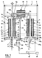
- FIG. 1 we see that we have designated by 1, as a whole, a fixed enclosure, constituted by a frame 2, composed of metal tubes and removable casings, the covers do not being shown in the drawing; these casings are thermally insulated and are attached to the frame 2, so as to form a tunnel comprising an inlet window 3 and an outlet window 4 for the passage of the containers 5 intended to be tested by the device.
- the middle line of the tunnel has the shape of a U.
- the containers 5 are placed one behind the other on a conveyor 6, the middle line of which is also U-shaped and is coincident with the middle line of the tunnel.
- the containers 5 enter the enclosure by one of the branches 6a of the U formed by the conveyor, through the entry window 3, and the exit is made by the other branch 6b, through the exit window 4.
- the outlet of the tunnel is equipped with a protective deflector 7, which is arranged obliquely with respect to the axis of this outlet, so that the containers 5, which exit from the tunnel, are deflected by said deflector 7 and taken up by a branch 6 c of the conveyor 6, outside the tunnel, parallel to the branch 6 b, and adjacent to the latter, the two branches 6 b and 6 c being adjacent in the region of said deflector 7.
- the conveyor 6 is constituted by pallets 8 on which the containers 5 rest, these pallets 8 being driven by a movable chain 9 mounted on a fixed support 10. Wheels 6 e ensure bending of the drive chain 9 at the two angles of the U; one of these two wheels 6 e constitutes the drive drum of the chain 6 and is associated with a notched wheel 200.
- the conveyor 6 can be made of plastic material because it is not heated by the infrared lamps. red 11 described below, the radiation being very directional.
- infrared lamps 11 which are ten in number and which are distributed as follows: four associated with branch 6 a, four associated with branch 6 and two associated with branch 6 d constituting the soul of the U, the lamps 11 being arranged in pairs, two lamps 11 of the same pair being opposite screw.
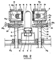
- FIG. 2 illustrates the mounting of each of the lamps 11 and shows the possibilities of adjustment, on the one hand, of its height, and, on the other hand, of its spacing with respect to the containers 5.
- Each lamp 11 (power of 2000 watts for example) consists of an infrared emitter 12 associated with a reflector 12 a cooled by a circulation of water 12 b; each lamp 11 is housed in a housing 13 secured to a base 14.
- the housing 13 of a lamp 11 has a parallelepiped shape, the longitudinal axis of which is arranged parallel to the branch of the conveyor 6, with which said lamp is associated 11. As can be seen in particular in FIG.
- the face 15 of the housing 13, which faces the conveyor 6 and in front of which the containers 5 will pass comprises two blades 16, 17 parallel to the longitudinal axis of said housing 13 , spaced from each other so as to constitute an intermediate space 18, means being provided so that this space is swept by a flow of compressed air (for example, at a relative pressure of 40,000 Pa).
- the inner blade 16 is a quartz blade, transparent to infrared radiation, but not very resistant to thermal shock.
- the outer blade 17 is made of glass of the type known under the brand name "Pyrex", very resistant to thermal and mechanical shock. The blades 17 prevent damage to the lamps 11, in the event that one of the containers 5 transported in the tunnel does not resist the pressure and explodes in the tunnel.
- the blades 16 and 17 are mounted in a plug 19 closing the body of the housing 13, on the face 15 of the latter.
- the internal blade 16 is applied against a seal ring 20 introduced into the opening of the housing body 13, said ring 20 being in abutment against the plug 19 and internally receiving a spacer element 21 which ensures the maintenance of a spacing between the blades 16 and 17;
- the outer blade 17 is held by an outer frame 22 with the interposition of a plate 23, the assembly 22-23 being screwed onto the front face of the plug 19.
- the body of the housing 13 externally comprises cooling fins 24, arranged in planes parallel to the longitudinal axis of said housing 13.
- the base 14 is made in two parts, one 25 being connected to the housing 13, and the other 26 being integral with the chassis 2, the facing end elements, respectively 27 and 28, of the parts 25 and 26 being in the form of plates which can slide one on the other, these plates being arranged in planes parallel to the longitudinal axis of the housing 13 and to the plane of movement of the chain 9.
- the part 25 is crossed by a threaded rod 29 which is perpendicular to the longitudinal axis of the housing 13 and which carries, on the side opposite to the face 15 of said housing 13, a butterfly valve 29 a allowing the spacing of the housing 13 to be adjusted. relative to the mean line of the transporter 6; the rod 29 is carried by a flange 30 integral with the plate 28 of the part 26 of the base 14.
- the plate 28 is integral with a foot 31 movable in height relative to the chassis 2.
- the foot 31 can slide in an opening in the chassis; it is blocked at the desired height by a seal 31 a, placed in a seat 31 b, this blocking being provided on a frame not shown in FIG. 2.
- the assembly which has just been described, comprises an automatic monitoring means, which is intended to control that each container 5, which enters the tunnel, leaves it after a given advancement of the conveyor 6, failing which safety is triggered.
- This monitoring means comprises, on the one hand, a means of tracking by step of the progress of the conveyor 6, and, on the other hand, a detection means intended to determine the presence or absence of a pressurized container 5 over an area having the length of a step for locating the progress of the conveyor 6.
- the aforementioned locating means consists of an optical transceiver, arranged outside the tunnel, in the vicinity of the drive drum of the transporter; this transceiver comprises, on one side of the notched wheel 200 integral with said drive drum of the transporter 6, a photo-diode 32 associated with a bundle of optical fibers 33, and, on the other side of said wheel with notches, a photo-transistor receiver 34, also associated with a bundle of optical fibers 35, the ends of the optical fibers 33, 35 being located opposite, so that each time a notch of the wheel passes in front of them, which corresponds to a step of advancement of the conveyor 6, the light beam is no longer obscured; in this case, the photo-transistor 34 emits a signal, which is transformed by a shaping component 134; the pulse obtained is identified by the reference numeral 36 on the diagram in FIG. 4.
- the detection means at the entrance to the tunnel consists of an optical transceiver placed inside said tunnel, just behind window 3. It consists, on the one hand, of an associated photo-diode 37 to a bundle of optical fibers 38, and, on the other hand, by a receiving photo-transistor 39 also associated with a bundle of optical fibers 40, the ends of the optical fibers 38 and 40 being arranged opposite the one from the other, on either side of the conveyor 6, so that each time the valve of a container 5 passes in front of them, the beam is obscured and the photo-transistor 39 emits a signal transformed into a voltage niche by a shaping component 139; this slot is designated by 41 on the diagram in FIG. 4. The width of the slots 41 is less than the distance separating two pulses 36.
- the detection means at the exit of the tunnel, arranged behind the exit window 4, has a structure strictly identical to that of the detection means at the entry; the organs which compose it are therefore identical to those of the detection means at the input and are identified by the same reference numbers followed by the letter "a".
- the input detection slots are sent to a shift register 141, the role of which is to delay n pulses, the significant marking of each slot, n being the number of steps that the carrier 6 has to take to transport a container. 5 from the entrance to the exit of the tunnel.
- a slot sent to the shift register 141 moves by one notch at each pulse 36 coming from the photo-transistor 34, so that when it has undergone n displacements in the shift register 141, it finds itself at the exit from the latter; the said output is compared with the corresponding output of the photo-transistor 39 a, in a comparator 42.
- the displacement of the slots in the shift register 141 is shown diagrammatically in the diagram of FIG. 4.
- the two inputs of comparator 42 are supplied in the same way, the output of the comparator is at zero; this corresponds to the case where the corresponding container 5 has correctly followed its path on the transporter 6 in the tunnel (presence of a slot on each entry) or if no container 5 was in the corresponding area of the transporter 6 (absence on each entry).
- the output of comparator 42 provides a voltage square 142 as shown on the last line of FIG. 4.
- the square 142 triggers a safety device 43, which causes the lights 11 and the transporter stop 6.
- the device according to the invention can also be equipped, in the three axes of the conveyor 6, with a flame detector sensitive to UV radiation. If a defective container 5 explodes in the tunnel and if the temperature causes the vapors thus released to self-ignite, the flame detector controls the opening of a container filled with incombustible gas under pressure; this gas occupies the entire interior space of the tunnel in a fraction of a second; this stops any risk of fire.
Landscapes
- Physics & Mathematics (AREA)
- General Physics & Mathematics (AREA)
- Immunology (AREA)
- Life Sciences & Earth Sciences (AREA)
- Chemical & Material Sciences (AREA)
- Analytical Chemistry (AREA)
- Biochemistry (AREA)
- General Health & Medical Sciences (AREA)
- Health & Medical Sciences (AREA)
- Pathology (AREA)
- Investigating Strength Of Materials By Application Of Mechanical Stress (AREA)
- Examining Or Testing Airtightness (AREA)
- Filling Or Discharging Of Gas Storage Vessels (AREA)
- Investigating Materials By The Use Of Optical Means Adapted For Particular Applications (AREA)
- Investigating Or Analyzing Materials Using Thermal Means (AREA)
- Control Of Conveyors (AREA)
- Testing Electric Properties And Detecting Electric Faults (AREA)
- Measurement Of Resistance Or Impedance (AREA)
- Testing Resistance To Weather, Investigating Materials By Mechanical Methods (AREA)
Claims (13)
Priority Applications (1)
| Application Number | Priority Date | Filing Date | Title |
|---|---|---|---|
| AT87402332T ATE53665T1 (de) | 1986-10-31 | 1987-10-19 | Vorrichtung zum pruefen der mechanischen festigkeit von druckbehaeltern bei erhoehter temperatur. |
Applications Claiming Priority (2)
| Application Number | Priority Date | Filing Date | Title |
|---|---|---|---|
| FR8615173A FR2606148B1 (fr) | 1986-10-31 | 1986-10-31 | Dispositif destine a tester a chaud la resistance mecanique de recipients pressurises |
| FR8615173 | 1986-10-31 |
Publications (2)
| Publication Number | Publication Date |
|---|---|
| EP0267832A1 EP0267832A1 (de) | 1988-05-18 |
| EP0267832B1 true EP0267832B1 (de) | 1990-06-13 |
Family
ID=9340389
Family Applications (1)
| Application Number | Title | Priority Date | Filing Date |
|---|---|---|---|
| EP87402332A Expired - Lifetime EP0267832B1 (de) | 1986-10-31 | 1987-10-19 | Vorrichtung zum Prüfen der mechanischen Festigkeit von Druckbehältern bei erhöhter Temperatur |
Country Status (9)
| Country | Link |
|---|---|
| US (1) | US4836013A (de) |
| EP (1) | EP0267832B1 (de) |
| JP (1) | JPS63139230A (de) |
| AT (1) | ATE53665T1 (de) |
| AU (1) | AU598863B2 (de) |
| CA (1) | CA1282255C (de) |
| DE (2) | DE267832T1 (de) |
| ES (1) | ES2002256B3 (de) |
| FR (1) | FR2606148B1 (de) |
Cited By (2)
| Publication number | Priority date | Publication date | Assignee | Title |
|---|---|---|---|---|
| CN106323554A (zh) * | 2016-09-13 | 2017-01-11 | 范全有 | 一种可选择更换led灯架的防水检测装置 |
| CN106441715A (zh) * | 2016-09-13 | 2017-02-22 | 范全有 | 一种可自由选择更换led灯架的防水检测装置 |
Families Citing this family (4)
| Publication number | Priority date | Publication date | Assignee | Title |
|---|---|---|---|---|
| US7002139B2 (en) * | 2003-04-23 | 2006-02-21 | Raytheon Company | Window mounting for optical sensor |
| RU2455557C1 (ru) * | 2010-12-23 | 2012-07-10 | Общество с ограниченной ответственностью НПО "ПОИСК" | Способ контроля работоспособности металлопластиковых баллонов и устройство для его осуществления |
| CN106441714B (zh) * | 2016-09-13 | 2018-12-21 | 金华市新鑫机电设备有限公司 | 一种带选择更换led灯架的防水检测装置 |
| CN116558803B (zh) * | 2023-05-12 | 2023-11-21 | 江苏宝强钢结构有限公司 | 一种可自动检测钢结构件水平应力装置 |
Family Cites Families (5)
| Publication number | Priority date | Publication date | Assignee | Title |
|---|---|---|---|---|
| GB996830A (en) * | 1961-12-12 | 1965-06-30 | Nealis Claremont Harrison | Improvements in and relating to the testing of vessels |
| US3350919A (en) * | 1964-07-24 | 1967-11-07 | Nalbach Eng Co J | Testing apparatus |
| DE1923012A1 (de) * | 1969-05-06 | 1970-11-19 | Schwarzkopf Gmbh Hans | Vorrichtung zur Pruefung der Dichtheit von Behaeltern,insbesondere Aerosoldosen |
| IT957204B (it) * | 1971-04-26 | 1973-10-10 | Waldherr J Ohg | Dispositivo di controllo per reci pienti a pressione |
| US3950982A (en) * | 1975-04-09 | 1976-04-20 | Houbigant, Inc. | Aerosol water bath |
-
1986
- 1986-10-31 FR FR8615173A patent/FR2606148B1/fr not_active Expired
-
1987
- 1987-10-13 CA CA000549167A patent/CA1282255C/fr not_active Expired - Lifetime
- 1987-10-14 US US07/109,262 patent/US4836013A/en not_active Expired - Fee Related
- 1987-10-19 AT AT87402332T patent/ATE53665T1/de not_active IP Right Cessation
- 1987-10-19 EP EP87402332A patent/EP0267832B1/de not_active Expired - Lifetime
- 1987-10-19 DE DE198787402332T patent/DE267832T1/de active Pending
- 1987-10-19 ES ES87402332T patent/ES2002256B3/es not_active Expired - Lifetime
- 1987-10-19 DE DE8787402332T patent/DE3763256D1/de not_active Expired - Lifetime
- 1987-10-30 JP JP62273614A patent/JPS63139230A/ja active Pending
- 1987-10-30 AU AU80525/87A patent/AU598863B2/en not_active Ceased
Cited By (4)
| Publication number | Priority date | Publication date | Assignee | Title |
|---|---|---|---|---|
| CN106323554A (zh) * | 2016-09-13 | 2017-01-11 | 范全有 | 一种可选择更换led灯架的防水检测装置 |
| CN106441715A (zh) * | 2016-09-13 | 2017-02-22 | 范全有 | 一种可自由选择更换led灯架的防水检测装置 |
| CN106323554B (zh) * | 2016-09-13 | 2018-06-15 | 中山市视际照明有限公司 | 一种可选择更换led灯架的防水检测装置 |
| CN106441715B (zh) * | 2016-09-13 | 2018-12-18 | 扬州悦扬光电科技有限公司 | 一种可自由选择更换led灯架的防水检测装置 |
Also Published As
| Publication number | Publication date |
|---|---|
| ATE53665T1 (de) | 1990-06-15 |
| ES2002256A4 (es) | 1988-08-01 |
| EP0267832A1 (de) | 1988-05-18 |
| AU8052587A (en) | 1988-05-05 |
| DE267832T1 (de) | 1988-11-03 |
| DE3763256D1 (de) | 1990-07-19 |
| JPS63139230A (ja) | 1988-06-11 |
| US4836013A (en) | 1989-06-06 |
| FR2606148A1 (fr) | 1988-05-06 |
| CA1282255C (fr) | 1991-04-02 |
| FR2606148B1 (fr) | 1989-01-06 |
| AU598863B2 (en) | 1990-07-05 |
| ES2002256B3 (es) | 1990-09-16 |
Similar Documents
| Publication | Publication Date | Title |
|---|---|---|
| EP0862016B1 (de) | Vorrichtung zur Beleuchtung von mindestens einem Wasserstrahls | |
| FR2684232A1 (fr) | Disjoncteur a vide muni de moyens d'autodiagnostic. | |
| FR2509213A1 (fr) | Dispositif pour perforer de la matiere en forme de feuille, en particulier dans l'industrie du tabac | |
| CH626711A5 (de) | ||
| CA1282255C (fr) | Dispositif destine a tester a chaud la resistance mecanique de recipients pressurises | |
| FR2542125A1 (fr) | Appareil et procede pour verifier les soudures des bouchons d'extremite de barres de combustible pour reacteur nucleaire | |
| EP0841031B1 (de) | Optisches Sicherheitsvorrichtung für Kochgeräte | |
| CH632090A5 (fr) | Machine de controle automatique de l'efficacite des fermetures de recipients. | |
| FR3053463A1 (fr) | Dispositif pour limiter l'angle d'incidence d'un spectrometre et procede de gestion du dispositif | |
| EP0000857B1 (de) | Photoelektrische Steuervorrichtung | |
| CH617511A5 (de) | ||
| EP0310526A1 (de) | Methode und Einrichtung für die Kontrolle des Druckes auf einer Dichtung oder in einem Behälter | |
| EP0002979A1 (de) | Einrichtung zur automatischen und registrierten Aufbewahrung und Abgabe von Zahlungsmitteln | |
| EP3363615A1 (de) | Einheit zum verarbeiten von vorformlingen mit einem optischen begrenzungsabschnitt mit konvergierenden wänden | |
| EP0263015B1 (de) | Optische Sortiervorrichtung zum Trennen zweier Arten von Teilchen mit unterschiedlicher optischer Durchlässigkeit | |
| EP0006556B1 (de) | Verfahren und Vorrichtung zum Abgeben einer bestimmten Flüssigkeitsmenge in ein Gefäss | |
| FR2754348A1 (fr) | Appareil pour la determination du point d'eclair d'un produit | |
| EP0533534B1 (de) | Gerät zum Absorbieren oder Ausstrahlen von Licht zu berührungslosen Objektvermessung | |
| FR2690412A1 (fr) | Dispositif d'emballage d'un paquet d'objets à l'aide d'un film en matériau plastique. | |
| FR2570489A1 (fr) | Procede et dispositif pour le controle des volumes de verre apres decoupe | |
| EP2521642B1 (de) | Einheit zur bearbeitung von hohlkörperrohlingen mit einer kammer zur formung einer lichtschleuse | |
| FR2563029A1 (fr) | Appareil distributeur de cigarettes allumees | |
| FR2562033A1 (fr) | Machine pour sceller automatiquement et en continu un film en matiere thermoplastique sur des paniers et emballage obtenu a l'aide d'une telle machine | |
| EP0801515B1 (de) | Widerstandvorrichtung zum Erwärmen von Behältern, bzw. Laborbehältern | |
| FR2572172A1 (fr) | Dispositif de transport et d'alimentation de munitions pour un canon a chargement automatique |
Legal Events
| Date | Code | Title | Description |
|---|---|---|---|
| PUAI | Public reference made under article 153(3) epc to a published international application that has entered the european phase |
Free format text: ORIGINAL CODE: 0009012 |
|
| 17P | Request for examination filed |
Effective date: 19871021 |
|
| AK | Designated contracting states |
Kind code of ref document: A1 Designated state(s): AT BE CH DE ES FR GB IT LI NL SE |
|
| ITCL | It: translation for ep claims filed |
Representative=s name: JACOBACCI CASETTA & PERANI S.P.A. |
|
| GBC | Gb: translation of claims filed (gb section 78(7)/1977) | ||
| TCAT | At: translation of patent claims filed | ||
| DET | De: translation of patent claims | ||
| 17Q | First examination report despatched |
Effective date: 19891020 |
|
| GRAA | (expected) grant |
Free format text: ORIGINAL CODE: 0009210 |
|
| AK | Designated contracting states |
Kind code of ref document: B1 Designated state(s): AT BE CH DE ES FR GB IT LI NL SE |
|
| REF | Corresponds to: |
Ref document number: 53665 Country of ref document: AT Date of ref document: 19900615 Kind code of ref document: T |
|
| ITF | It: translation for a ep patent filed | ||
| GBT | Gb: translation of ep patent filed (gb section 77(6)(a)/1977) | ||
| REF | Corresponds to: |
Ref document number: 3763256 Country of ref document: DE Date of ref document: 19900719 |
|
| PLBE | No opposition filed within time limit |
Free format text: ORIGINAL CODE: 0009261 |
|
| STAA | Information on the status of an ep patent application or granted ep patent |
Free format text: STATUS: NO OPPOSITION FILED WITHIN TIME LIMIT |
|
| 26N | No opposition filed | ||
| PGFP | Annual fee paid to national office [announced via postgrant information from national office to epo] |
Ref country code: SE Payment date: 19911018 Year of fee payment: 5 |
|
| PGFP | Annual fee paid to national office [announced via postgrant information from national office to epo] |
Ref country code: NL Payment date: 19911031 Year of fee payment: 5 |
|
| PGFP | Annual fee paid to national office [announced via postgrant information from national office to epo] |
Ref country code: DE Payment date: 19911223 Year of fee payment: 5 |
|
| PGFP | Annual fee paid to national office [announced via postgrant information from national office to epo] |
Ref country code: AT Payment date: 19920925 Year of fee payment: 6 |
|
| PG25 | Lapsed in a contracting state [announced via postgrant information from national office to epo] |
Ref country code: SE Effective date: 19921020 |
|
| ITTA | It: last paid annual fee | ||
| PG25 | Lapsed in a contracting state [announced via postgrant information from national office to epo] |
Ref country code: NL Effective date: 19930501 |
|
| NLV4 | Nl: lapsed or anulled due to non-payment of the annual fee | ||
| PG25 | Lapsed in a contracting state [announced via postgrant information from national office to epo] |
Ref country code: DE Effective date: 19930701 |
|
| PG25 | Lapsed in a contracting state [announced via postgrant information from national office to epo] |
Ref country code: AT Effective date: 19931019 |
|
| EUG | Se: european patent has lapsed |
Ref document number: 87402332.8 Effective date: 19930510 |
|
| PGFP | Annual fee paid to national office [announced via postgrant information from national office to epo] |
Ref country code: GB Payment date: 19960930 Year of fee payment: 10 |
|
| PGFP | Annual fee paid to national office [announced via postgrant information from national office to epo] |
Ref country code: ES Payment date: 19961007 Year of fee payment: 10 |
|
| PGFP | Annual fee paid to national office [announced via postgrant information from national office to epo] |
Ref country code: FR Payment date: 19961025 Year of fee payment: 10 |
|
| PGFP | Annual fee paid to national office [announced via postgrant information from national office to epo] |
Ref country code: CH Payment date: 19961212 Year of fee payment: 10 Ref country code: BE Payment date: 19961212 Year of fee payment: 10 |
|
| PG25 | Lapsed in a contracting state [announced via postgrant information from national office to epo] |
Ref country code: GB Free format text: LAPSE BECAUSE OF NON-PAYMENT OF DUE FEES Effective date: 19971019 |
|
| PG25 | Lapsed in a contracting state [announced via postgrant information from national office to epo] |
Ref country code: ES Free format text: LAPSE BECAUSE OF THE APPLICANT RENOUNCES Effective date: 19971020 |
|
| PG25 | Lapsed in a contracting state [announced via postgrant information from national office to epo] |
Ref country code: LI Free format text: LAPSE BECAUSE OF NON-PAYMENT OF DUE FEES Effective date: 19971031 Ref country code: FR Free format text: THE PATENT HAS BEEN ANNULLED BY A DECISION OF A NATIONAL AUTHORITY Effective date: 19971031 Ref country code: CH Free format text: LAPSE BECAUSE OF NON-PAYMENT OF DUE FEES Effective date: 19971031 Ref country code: BE Free format text: LAPSE BECAUSE OF NON-PAYMENT OF DUE FEES Effective date: 19971031 |
|
| BERE | Be: lapsed |
Owner name: L' OREAL Effective date: 19971031 |
|
| GBPC | Gb: european patent ceased through non-payment of renewal fee |
Effective date: 19971019 |
|
| REG | Reference to a national code |
Ref country code: CH Ref legal event code: PL |
|
| REG | Reference to a national code |
Ref country code: FR Ref legal event code: ST |
|
| REG | Reference to a national code |
Ref country code: ES Ref legal event code: FD2A Effective date: 20001009 |
|
| PG25 | Lapsed in a contracting state [announced via postgrant information from national office to epo] |
Ref country code: IT Free format text: LAPSE BECAUSE OF NON-PAYMENT OF DUE FEES;WARNING: LAPSES OF ITALIAN PATENTS WITH EFFECTIVE DATE BEFORE 2007 MAY HAVE OCCURRED AT ANY TIME BEFORE 2007. THE CORRECT EFFECTIVE DATE MAY BE DIFFERENT FROM THE ONE RECORDED. Effective date: 20051019 |