EP0267937B1 - Dispositif de soudage et de perforation d'un film thermoplastique replie sur lui-meme - Google Patents
Dispositif de soudage et de perforation d'un film thermoplastique replie sur lui-meme Download PDFInfo
- Publication number
- EP0267937B1 EP0267937B1 EP87903340A EP87903340A EP0267937B1 EP 0267937 B1 EP0267937 B1 EP 0267937B1 EP 87903340 A EP87903340 A EP 87903340A EP 87903340 A EP87903340 A EP 87903340A EP 0267937 B1 EP0267937 B1 EP 0267937B1
- Authority
- EP
- European Patent Office
- Prior art keywords
- film
- perforating
- welding
- sealing
- heating
- Prior art date
- Legal status (The legal status is an assumption and is not a legal conclusion. Google has not performed a legal analysis and makes no representation as to the accuracy of the status listed.)
- Expired - Lifetime
Links
Images


Classifications
-
- B—PERFORMING OPERATIONS; TRANSPORTING
- B29—WORKING OF PLASTICS; WORKING OF SUBSTANCES IN A PLASTIC STATE IN GENERAL
- B29C—SHAPING OR JOINING OF PLASTICS; SHAPING OF MATERIAL IN A PLASTIC STATE, NOT OTHERWISE PROVIDED FOR; AFTER-TREATMENT OF THE SHAPED PRODUCTS, e.g. REPAIRING
- B29C65/00—Joining or sealing of preformed parts, e.g. welding of plastics materials; Apparatus therefor
- B29C65/02—Joining or sealing of preformed parts, e.g. welding of plastics materials; Apparatus therefor by heating, with or without pressure
- B29C65/18—Joining or sealing of preformed parts, e.g. welding of plastics materials; Apparatus therefor by heating, with or without pressure using heated tools
- B29C65/22—Heated wire resistive ribbon, resistive band or resistive strip
- B29C65/221—Heated wire resistive ribbon, resistive band or resistive strip characterised by the type of heated wire, resistive ribbon, band or strip
- B29C65/224—Heated wire resistive ribbon, resistive band or resistive strip characterised by the type of heated wire, resistive ribbon, band or strip being a resistive ribbon, a resistive band or a resistive strip
-
- B—PERFORMING OPERATIONS; TRANSPORTING
- B29—WORKING OF PLASTICS; WORKING OF SUBSTANCES IN A PLASTIC STATE IN GENERAL
- B29C—SHAPING OR JOINING OF PLASTICS; SHAPING OF MATERIAL IN A PLASTIC STATE, NOT OTHERWISE PROVIDED FOR; AFTER-TREATMENT OF THE SHAPED PRODUCTS, e.g. REPAIRING
- B29C65/00—Joining or sealing of preformed parts, e.g. welding of plastics materials; Apparatus therefor
- B29C65/02—Joining or sealing of preformed parts, e.g. welding of plastics materials; Apparatus therefor by heating, with or without pressure
- B29C65/18—Joining or sealing of preformed parts, e.g. welding of plastics materials; Apparatus therefor by heating, with or without pressure using heated tools
- B29C65/22—Heated wire resistive ribbon, resistive band or resistive strip
- B29C65/228—Heated wire resistive ribbon, resistive band or resistive strip characterised by the means for electrically connecting the ends of said heated wire, resistive ribbon, resistive band or resistive strip
-
- B—PERFORMING OPERATIONS; TRANSPORTING
- B29—WORKING OF PLASTICS; WORKING OF SUBSTANCES IN A PLASTIC STATE IN GENERAL
- B29C—SHAPING OR JOINING OF PLASTICS; SHAPING OF MATERIAL IN A PLASTIC STATE, NOT OTHERWISE PROVIDED FOR; AFTER-TREATMENT OF THE SHAPED PRODUCTS, e.g. REPAIRING
- B29C65/00—Joining or sealing of preformed parts, e.g. welding of plastics materials; Apparatus therefor
- B29C65/74—Joining or sealing of preformed parts, e.g. welding of plastics materials; Apparatus therefor by welding and severing, or by joining and severing, the severing being performed in the area to be joined, next to the area to be joined, in the joint area or next to the joint area
- B29C65/743—Joining or sealing of preformed parts, e.g. welding of plastics materials; Apparatus therefor by welding and severing, or by joining and severing, the severing being performed in the area to be joined, next to the area to be joined, in the joint area or next to the joint area using the same tool for both joining and severing, said tool being monobloc or formed by several parts mounted together and forming a monobloc
- B29C65/7441—Joining or sealing of preformed parts, e.g. welding of plastics materials; Apparatus therefor by welding and severing, or by joining and severing, the severing being performed in the area to be joined, next to the area to be joined, in the joint area or next to the joint area using the same tool for both joining and severing, said tool being monobloc or formed by several parts mounted together and forming a monobloc for making welds and cuts of other than simple rectilinear form
-
- B—PERFORMING OPERATIONS; TRANSPORTING
- B29—WORKING OF PLASTICS; WORKING OF SUBSTANCES IN A PLASTIC STATE IN GENERAL
- B29C—SHAPING OR JOINING OF PLASTICS; SHAPING OF MATERIAL IN A PLASTIC STATE, NOT OTHERWISE PROVIDED FOR; AFTER-TREATMENT OF THE SHAPED PRODUCTS, e.g. REPAIRING
- B29C66/00—General aspects of processes or apparatus for joining preformed parts
- B29C66/01—General aspects dealing with the joint area or with the area to be joined
- B29C66/05—Particular design of joint configurations
- B29C66/20—Particular design of joint configurations particular design of the joint lines, e.g. of the weld lines
- B29C66/24—Particular design of joint configurations particular design of the joint lines, e.g. of the weld lines said joint lines being closed or non-straight
- B29C66/244—Particular design of joint configurations particular design of the joint lines, e.g. of the weld lines said joint lines being closed or non-straight said joint lines being non-straight, e.g. forming non-closed contours
- B29C66/2442—Particular design of joint configurations particular design of the joint lines, e.g. of the weld lines said joint lines being closed or non-straight said joint lines being non-straight, e.g. forming non-closed contours in the form of a single arc of circle
-
- B—PERFORMING OPERATIONS; TRANSPORTING
- B29—WORKING OF PLASTICS; WORKING OF SUBSTANCES IN A PLASTIC STATE IN GENERAL
- B29C—SHAPING OR JOINING OF PLASTICS; SHAPING OF MATERIAL IN A PLASTIC STATE, NOT OTHERWISE PROVIDED FOR; AFTER-TREATMENT OF THE SHAPED PRODUCTS, e.g. REPAIRING
- B29C66/00—General aspects of processes or apparatus for joining preformed parts
- B29C66/40—General aspects of joining substantially flat articles, e.g. plates, sheets or web-like materials; Making flat seams in tubular or hollow articles; Joining single elements to substantially flat surfaces
- B29C66/41—Joining substantially flat articles ; Making flat seams in tubular or hollow articles
- B29C66/43—Joining a relatively small portion of the surface of said articles
- B29C66/432—Joining a relatively small portion of the surface of said articles for making tubular articles or closed loops, e.g. by joining several sheets ; for making hollow articles or hollow preforms
- B29C66/4322—Joining a relatively small portion of the surface of said articles for making tubular articles or closed loops, e.g. by joining several sheets ; for making hollow articles or hollow preforms by joining a single sheet to itself
-
- B—PERFORMING OPERATIONS; TRANSPORTING
- B29—WORKING OF PLASTICS; WORKING OF SUBSTANCES IN A PLASTIC STATE IN GENERAL
- B29C—SHAPING OR JOINING OF PLASTICS; SHAPING OF MATERIAL IN A PLASTIC STATE, NOT OTHERWISE PROVIDED FOR; AFTER-TREATMENT OF THE SHAPED PRODUCTS, e.g. REPAIRING
- B29C66/00—General aspects of processes or apparatus for joining preformed parts
- B29C66/80—General aspects of machine operations or constructions and parts thereof
- B29C66/81—General aspects of the pressing elements, i.e. the elements applying pressure on the parts to be joined in the area to be joined, e.g. the welding jaws or clamps
- B29C66/814—General aspects of the pressing elements, i.e. the elements applying pressure on the parts to be joined in the area to be joined, e.g. the welding jaws or clamps characterised by the design of the pressing elements, e.g. of the welding jaws or clamps
- B29C66/8141—General aspects of the pressing elements, i.e. the elements applying pressure on the parts to be joined in the area to be joined, e.g. the welding jaws or clamps characterised by the design of the pressing elements, e.g. of the welding jaws or clamps characterised by the surface geometry of the part of the pressing elements, e.g. welding jaws or clamps, coming into contact with the parts to be joined
- B29C66/81427—General aspects of the pressing elements, i.e. the elements applying pressure on the parts to be joined in the area to be joined, e.g. the welding jaws or clamps characterised by the design of the pressing elements, e.g. of the welding jaws or clamps characterised by the surface geometry of the part of the pressing elements, e.g. welding jaws or clamps, coming into contact with the parts to be joined comprising a single ridge, e.g. for making a weakening line; comprising a single tooth
-
- B—PERFORMING OPERATIONS; TRANSPORTING
- B29—WORKING OF PLASTICS; WORKING OF SUBSTANCES IN A PLASTIC STATE IN GENERAL
- B29C—SHAPING OR JOINING OF PLASTICS; SHAPING OF MATERIAL IN A PLASTIC STATE, NOT OTHERWISE PROVIDED FOR; AFTER-TREATMENT OF THE SHAPED PRODUCTS, e.g. REPAIRING
- B29C66/00—General aspects of processes or apparatus for joining preformed parts
- B29C66/80—General aspects of machine operations or constructions and parts thereof
- B29C66/81—General aspects of the pressing elements, i.e. the elements applying pressure on the parts to be joined in the area to be joined, e.g. the welding jaws or clamps
- B29C66/818—General aspects of the pressing elements, i.e. the elements applying pressure on the parts to be joined in the area to be joined, e.g. the welding jaws or clamps characterised by the cooling constructional aspects, or by the thermal or electrical insulating or conducting constructional aspects of the welding jaws or of the clamps ; comprising means for compensating for the thermal expansion of the welding jaws or of the clamps
- B29C66/8182—General aspects of the pressing elements, i.e. the elements applying pressure on the parts to be joined in the area to be joined, e.g. the welding jaws or clamps characterised by the cooling constructional aspects, or by the thermal or electrical insulating or conducting constructional aspects of the welding jaws or of the clamps ; comprising means for compensating for the thermal expansion of the welding jaws or of the clamps characterised by the thermal insulating constructional aspects
- B29C66/81821—General aspects of the pressing elements, i.e. the elements applying pressure on the parts to be joined in the area to be joined, e.g. the welding jaws or clamps characterised by the cooling constructional aspects, or by the thermal or electrical insulating or conducting constructional aspects of the welding jaws or of the clamps ; comprising means for compensating for the thermal expansion of the welding jaws or of the clamps characterised by the thermal insulating constructional aspects of the welding jaws
-
- B—PERFORMING OPERATIONS; TRANSPORTING
- B29—WORKING OF PLASTICS; WORKING OF SUBSTANCES IN A PLASTIC STATE IN GENERAL
- B29C—SHAPING OR JOINING OF PLASTICS; SHAPING OF MATERIAL IN A PLASTIC STATE, NOT OTHERWISE PROVIDED FOR; AFTER-TREATMENT OF THE SHAPED PRODUCTS, e.g. REPAIRING
- B29C66/00—General aspects of processes or apparatus for joining preformed parts
- B29C66/80—General aspects of machine operations or constructions and parts thereof
- B29C66/81—General aspects of the pressing elements, i.e. the elements applying pressure on the parts to be joined in the area to be joined, e.g. the welding jaws or clamps
- B29C66/818—General aspects of the pressing elements, i.e. the elements applying pressure on the parts to be joined in the area to be joined, e.g. the welding jaws or clamps characterised by the cooling constructional aspects, or by the thermal or electrical insulating or conducting constructional aspects of the welding jaws or of the clamps ; comprising means for compensating for the thermal expansion of the welding jaws or of the clamps
- B29C66/8187—General aspects of the pressing elements, i.e. the elements applying pressure on the parts to be joined in the area to be joined, e.g. the welding jaws or clamps characterised by the cooling constructional aspects, or by the thermal or electrical insulating or conducting constructional aspects of the welding jaws or of the clamps ; comprising means for compensating for the thermal expansion of the welding jaws or of the clamps characterised by the electrical insulating constructional aspects
- B29C66/81871—General aspects of the pressing elements, i.e. the elements applying pressure on the parts to be joined in the area to be joined, e.g. the welding jaws or clamps characterised by the cooling constructional aspects, or by the thermal or electrical insulating or conducting constructional aspects of the welding jaws or of the clamps ; comprising means for compensating for the thermal expansion of the welding jaws or of the clamps characterised by the electrical insulating constructional aspects of the welding jaws
-
- B—PERFORMING OPERATIONS; TRANSPORTING
- B29—WORKING OF PLASTICS; WORKING OF SUBSTANCES IN A PLASTIC STATE IN GENERAL
- B29C—SHAPING OR JOINING OF PLASTICS; SHAPING OF MATERIAL IN A PLASTIC STATE, NOT OTHERWISE PROVIDED FOR; AFTER-TREATMENT OF THE SHAPED PRODUCTS, e.g. REPAIRING
- B29C66/00—General aspects of processes or apparatus for joining preformed parts
- B29C66/80—General aspects of machine operations or constructions and parts thereof
- B29C66/83—General aspects of machine operations or constructions and parts thereof characterised by the movement of the joining or pressing tools
- B29C66/836—Moving relative to and tangentially to the parts to be joined, e.g. transversely to the displacement of the parts to be joined, e.g. using a X-Y table
-
- B—PERFORMING OPERATIONS; TRANSPORTING
- B29—WORKING OF PLASTICS; WORKING OF SUBSTANCES IN A PLASTIC STATE IN GENERAL
- B29C—SHAPING OR JOINING OF PLASTICS; SHAPING OF MATERIAL IN A PLASTIC STATE, NOT OTHERWISE PROVIDED FOR; AFTER-TREATMENT OF THE SHAPED PRODUCTS, e.g. REPAIRING
- B29C66/00—General aspects of processes or apparatus for joining preformed parts
- B29C66/01—General aspects dealing with the joint area or with the area to be joined
- B29C66/05—Particular design of joint configurations
- B29C66/10—Particular design of joint configurations particular design of the joint cross-sections
- B29C66/11—Joint cross-sections comprising a single joint-segment, i.e. one of the parts to be joined comprising a single joint-segment in the joint cross-section
- B29C66/114—Single butt joints
- B29C66/1142—Single butt to butt joints
-
- B—PERFORMING OPERATIONS; TRANSPORTING
- B29—WORKING OF PLASTICS; WORKING OF SUBSTANCES IN A PLASTIC STATE IN GENERAL
- B29C—SHAPING OR JOINING OF PLASTICS; SHAPING OF MATERIAL IN A PLASTIC STATE, NOT OTHERWISE PROVIDED FOR; AFTER-TREATMENT OF THE SHAPED PRODUCTS, e.g. REPAIRING
- B29C66/00—General aspects of processes or apparatus for joining preformed parts
- B29C66/01—General aspects dealing with the joint area or with the area to be joined
- B29C66/347—General aspects dealing with the joint area or with the area to be joined using particular temperature distributions or gradients; using particular heat distributions or gradients
-
- B—PERFORMING OPERATIONS; TRANSPORTING
- B29—WORKING OF PLASTICS; WORKING OF SUBSTANCES IN A PLASTIC STATE IN GENERAL
- B29L—INDEXING SCHEME ASSOCIATED WITH SUBCLASS B29C, RELATING TO PARTICULAR ARTICLES
- B29L2031/00—Other particular articles
- B29L2031/46—Knobs or handles, push-buttons, grips
- B29L2031/463—Grips, handles
-
- B—PERFORMING OPERATIONS; TRANSPORTING
- B29—WORKING OF PLASTICS; WORKING OF SUBSTANCES IN A PLASTIC STATE IN GENERAL
- B29L—INDEXING SCHEME ASSOCIATED WITH SUBCLASS B29C, RELATING TO PARTICULAR ARTICLES
- B29L2031/00—Other particular articles
- B29L2031/712—Containers; Packaging elements or accessories, Packages
- B29L2031/7128—Bags, sacks, sachets
-
- B—PERFORMING OPERATIONS; TRANSPORTING
- B29—WORKING OF PLASTICS; WORKING OF SUBSTANCES IN A PLASTIC STATE IN GENERAL
- B29L—INDEXING SCHEME ASSOCIATED WITH SUBCLASS B29C, RELATING TO PARTICULAR ARTICLES
- B29L2031/00—Other particular articles
- B29L2031/712—Containers; Packaging elements or accessories, Packages
- B29L2031/7148—Blood bags, medical bags
-
- B—PERFORMING OPERATIONS; TRANSPORTING
- B31—MAKING ARTICLES OF PAPER, CARDBOARD OR MATERIAL WORKED IN A MANNER ANALOGOUS TO PAPER; WORKING PAPER, CARDBOARD OR MATERIAL WORKED IN A MANNER ANALOGOUS TO PAPER
- B31B—MAKING CONTAINERS OF PAPER, CARDBOARD OR MATERIAL WORKED IN A MANNER ANALOGOUS TO PAPER
- B31B70/00—Making flexible containers, e.g. envelopes or bags
- B31B70/14—Cutting, e.g. perforating, punching, slitting or trimming
-
- B—PERFORMING OPERATIONS; TRANSPORTING
- B31—MAKING ARTICLES OF PAPER, CARDBOARD OR MATERIAL WORKED IN A MANNER ANALOGOUS TO PAPER; WORKING PAPER, CARDBOARD OR MATERIAL WORKED IN A MANNER ANALOGOUS TO PAPER
- B31B—MAKING CONTAINERS OF PAPER, CARDBOARD OR MATERIAL WORKED IN A MANNER ANALOGOUS TO PAPER
- B31B70/00—Making flexible containers, e.g. envelopes or bags
- B31B70/60—Uniting opposed surfaces or edges; Taping
- B31B70/64—Uniting opposed surfaces or edges; Taping by applying heat or pressure
- B31B70/642—Uniting opposed surfaces or edges; Taping by applying heat or pressure using sealing jaws or sealing dies
-
- Y—GENERAL TAGGING OF NEW TECHNOLOGICAL DEVELOPMENTS; GENERAL TAGGING OF CROSS-SECTIONAL TECHNOLOGIES SPANNING OVER SEVERAL SECTIONS OF THE IPC; TECHNICAL SUBJECTS COVERED BY FORMER USPC CROSS-REFERENCE ART COLLECTIONS [XRACs] AND DIGESTS
- Y10—TECHNICAL SUBJECTS COVERED BY FORMER USPC
- Y10T—TECHNICAL SUBJECTS COVERED BY FORMER US CLASSIFICATION
- Y10T156/00—Adhesive bonding and miscellaneous chemical manufacture
- Y10T156/12—Surface bonding means and/or assembly means with cutting, punching, piercing, severing or tearing
- Y10T156/1313—Cutting element simultaneously bonds [e.g., cut seaming]
-
- Y—GENERAL TAGGING OF NEW TECHNOLOGICAL DEVELOPMENTS; GENERAL TAGGING OF CROSS-SECTIONAL TECHNOLOGIES SPANNING OVER SEVERAL SECTIONS OF THE IPC; TECHNICAL SUBJECTS COVERED BY FORMER USPC CROSS-REFERENCE ART COLLECTIONS [XRACs] AND DIGESTS
- Y10—TECHNICAL SUBJECTS COVERED BY FORMER USPC
- Y10T—TECHNICAL SUBJECTS COVERED BY FORMER US CLASSIFICATION
- Y10T156/00—Adhesive bonding and miscellaneous chemical manufacture
- Y10T156/17—Surface bonding means and/or assemblymeans with work feeding or handling means
- Y10T156/1702—For plural parts or plural areas of single part
- Y10T156/1712—Indefinite or running length work
- Y10T156/1737—Discontinuous, spaced area, and/or patterned pressing
Definitions
- the present invention relates to a device for welding and perforating a thermoplastic film folded back on itself;
- the invention applies in particular, although not exclusively, to the production of infusion bags.
- Machines are known for producing bags from a flexible plastic film.
- machines are known for producing bags from a thermoplastic film according to the preamble of claim 1. These machines include a series of stations where the film is treated successively.
- the film is unwound from a winder, then perforated.
- end pieces are welded by a welding head, then the film is shaped in a former mainly intended to fold the film over itself in order to perform edge-to-edge welding.
- the film thus welded edge to edge forms a tube which is then welded transversely at regular intervals in order to produce individual pockets, these individual pockets being filled prior to the closure of the pocket.
- the present invention relates more particularly to the device intended to perform the edge-to-edge welding of the film folded back on itself.
- weld (s) are generally carried out by means of a weld tape comprising a heating part, the welded film naturally cooling at the outlet of the welding station.
- a weld tape comprising a heating part
- the welded film naturally cooling at the outlet of the welding station.
- Such a structure has drawbacks, in particular in high-speed machines where the heating tapes must be brought to a high temperature to effect rapid welding. There is indeed in this case a risk that the forces exerted on the film at its exit from the welding station cause a separation, at least partial, of the parts of associated films so that the weld is no longer waterproof or in any case too weak.
- An object of the present invention is to provide a device for welding and perforating a thermoplastic film folded back on itself which allows the production of an improved pocket which does not have the aforementioned drawbacks.
- a device for welding and perforating a thermoplastic film folded back on itself, driven step by step comprising a support movable transversely to the film and means heaters carried by the mobile support, these heating means comprising two electrically conductive welding ribbons spaced from each other and each comprising a heating part by passage of an electric current, and perforation means disposed between the welding ribbons, in which the welding ribbons comprise a non-heating part of length at least equal to the heating part and arranged downstream of the heating part in a direction of movement of the film.
- the welds of the edges of the film are successively carried out by the heating part of the welding tapes then cooled and flattened by the non-heating part of the welding tapes, which avoids subsequent deformation. welded film.
- the perforation means are mounted on a base which is movable parallel to a longitudinal direction of the welding tapes.
- the position of the attachment opening is adjusted at will.
- the perforation means comprise a perforating tape heating by the passage of an electric current and having a longitudinal rib facing the film.
- the longitudinal rib produces a hooking slot while the lateral portions of the tape carry out a welding on either side of the hooking slot. This further improves the tear resistance of the attachment opening and eliminates the risk of introducing pollutants between the two film thicknesses at the attachment opening.
- the perforation tape has folded ends engaged in a first end of tubular connecting rods and welded to them, the tubular connecting rods having a second end equipped with an insert welded.
- Punching means generally designated at 8 are carried by the mobile support 4 between the heating parts 7.1 of the welding tapes 7.
- the perforation means 8 are mounted on a base 9 which is movable parallel to the longitudinal direction of the welding tapes 7. More specifically, the mobile base 9 is disposed in an opening 10 made between the tapes welding 7 and having shoulders 11 and 12 on which bear corresponding shoulders of the movable base 9. At the rear part of the movable support 4, the opening 10 opens into a slot 13 through which passes a threaded rod 14 screwed to a of its ends in the movable base 9 and the other end of which is connected to a knurled button 15 bearing on the edges of the slot 13 by means of a plastic washer 16.
- the button is tightened softness 15 the movable base 9 is locked in abutment against the shoulders 11 and 12, while when the knurled button 15 is released, the mobile base 9 is free to move in the opening 10 parallel to the welding tapes 7.
- the perforation means comprise a perforation tape 17 heating by the passage of an electric current and having a longitudinal rib 18 facing the film.
- the perforation strip 17 is a profiled strip curved in the shape of a C and the ends of which are folded perpendicular to the plane of the strip and engaged in a first end of tubular connecting rods 19 to which they are welded by a weld 20.
- the second end of each connecting rod 19 is equipped with an insert 21 welded into the connecting rod.
- the base 9 has bores 22 in which are arranged electrically insulating tubes 23.
- the connecting rods 19 When the connecting rods 19 are engaged in the insulating tubes 23, the perforation tape 17 bears against an electrically plate and thermally insulating 24 inserted in the front face of the movable base 9.
- the inserts 21 located at the ends of the connecting rods 19 are locked in lugs 25, themselves arranged in an insulating block 26, by means of locking screws 27.
- the lugs 25 are conventionally connected to power cables 28.
- conduits 29 connected to a source of cooling fluid.
- the film 1 is advanced step by step between the mobile support 4 and the plywood 6.
- the mobile support is advanced towards the film and a current is sent to the welding tapes 7 and the perforation tape 17.
- the lateral parts of the tape 17 weld while the rib 18 passes through the two thicknesses of the film.
- the film 1 has advanced one step after welding and perforation, it is again pressed by the movable support 4 at the cold parts 7.2 of the welding tapes 7.
- the welds which are still hot are maintained flattened while being cooled, so that at the exit of the device the film comprises two flat welds 30 (FIG.
- the ribbon perforation 17 can be made in the form of a circular ring in order to produce an opening of the same shape in the tongue, the connecting rods 19 then being welded perpendicular to the rear face of the circular ring.
Landscapes
- Engineering & Computer Science (AREA)
- Mechanical Engineering (AREA)
- Physics & Mathematics (AREA)
- Thermal Sciences (AREA)
- Lining Or Joining Of Plastics Or The Like (AREA)
- Making Paper Articles (AREA)
- Package Closures (AREA)
Abstract
Description
- La présente invention concerne un dispositif de soudage et de perforation d'un film thermoplastique replié sur lui-même; L'invention s'applique notamment, bien que non exclusivement, à la réalisation de poches de perfusion.
- On connaît des machines pour la réalisation de poches à partir d'un film souple en matière plastique. En particulier, on connaît des machines pour la réalisation de poches à partir d'un film thermoplastique selon le préambule de la revendication 1. Ces machines comprennent une série de postes où le film est traité de façon successive. En général, le film est déroulé à partir d'un bobinoir, puis perforé. Au droit des perforations, des embouts sont soudés par une tête de soudage puis le film est conformé dans un conformateur principalement destiné à replier le film sur lui-mime en vue d'effectuer une soudure bord à bord. Le film ainsi soudé bord à bord forme un tube qui est ensuite soudé transversalement à intervalles réguliers afin de réaliser des poches individuelles, ces poches individuelles étant remplies préalablement à la réalisation de la fermeture de la poche.
- La présente invention concerne plus particulièrement le dispositif destiné à réaliser la soudure bord à bord du film replié sur lui-même.
- On connaît des dispositifs permettant d'effectuer une soudure parallèle au bord ou même deux soudures parallèles au bord et espacées l'une de l'autre afin de délimiter une languette dans laquelle une perforation peut être effectuée pour réaliser une ouverture d'accrochage de la poche (FR-A-2 394 461). La ou les soudures sont généralement effectuées au moyen d'un ruban de soudure comportant une partie chauffante, le film soudé se refroidissant naturellement à la sortie du poste de soudage. Une telle structure présente des inconvénients en particulier dans les machines de cadence élevée où les rubans de chauffage doivent être portés à une température élevée pour effectuer une soudure rapide. Il existe en effet dans ce cas un risque que les efforts exercés sur le film à sa sortie du poste de soudage provoquent une séparation, au moins partielle, des parties de films associées de sorte que la soudure n'est plus étanche ou en tout cas trop fragile.
- Un but de la présente invention est de proposer un dispositif de soudage et de perforation d'un film thermoplastique replié sur lui-môme qui permette la réalisation d'une poche améliorée ne présentant pas les inconvénients précités.
- En vue de la réalisation de ce but, on prévoit, selon l'invention, un dispositif de soudage et de perforation d'un film thermoplastique replié sur lui-même, entraîné pas à pas, comportant un support mobile transversalement au film et des moyens chauffants portés par le support mobile, ces moyens chauffants comprenant deux rubans de soudage conducteurs de l'électricité espacés l'un de l'autre et comportant chacun une partie chauffante par passage d'un courant électrique, et des moyens de perforation disposés entre les rubans de soudage, dans lequel les rubans de soudage comportent une partie non chauffante de longueur au moins égale à la partie chauffante et disposée en aval de la partie chauffante selon une direction de déplacement du film.
- Ainsi, lors de l'avance pas à pas du film, les soudures des bords du film sont successivement réalisées par la partie chauffante des rubans de soudage puis refroidies et aplaties par la partie non chauffante des rubans de soudage, ce qui évite une déformation ultérieure du film soudé.
- Selon une version avantageuse de l'invention, les moyens de perforation sont montés sur un socle qui est mobile parallèlement à une direction longitudinale des rubans de soudage. Ainsi, on règle à volonté la position de l'ouverture d'accrochage. En particulier, lorsque la machine est utilisée pour réaliser des poches de différentes largeurs, il est possible de disposer les moyens de perforation pour que l'ouverture d'accrochage soit systématiquement réalisée au milieu de la largeur de la poche.
- Selon un autre aspect avantageux de l'invention, les moyens de perforation comprennent un ruban de perforation chauffant par passage d'un courant électrique et présentant une nervure longitudinale tournée vers le film. Ainsi, lors de l'application du dispositif de soudage et de perforation du film, la nervure longitudinale réalise une fente d'accrochage tandis que les parties latérales du ruban réalisent une soudure de part et d'autre de la fente d'accrochage. On améliore ainsi encore la résistance au déchirement de l'ouverture d'accrochage et on supprime le risque d'introduction d'éléments polluants entre les deux épaisseurs de film au niveau de l'ouverture d'accrochage.
- Selon un mode de réalisation avantageux de l'invention, le ruban de perforation comporte des extrémités repliées engagées dans une première extrémité de tiges de liaison tubulaires et soudées à celles-ci, les tiges de liaison tubulaires ayant une seconde extrémité équipée d'un insert soudé. Ainsi on assure une bonne liaison, tant mécanique qu'électrique, entre le ruban de perforation et les tiges de liaison servant à l'alimentation électrique du ruban de perforation.
- D'autres caractéristiques et avantages de l'invention ressortiront encore de la description détaillée d'un mode de réalisation préféré de l'invention en liaison avec les dessins ci-joints parmi lesquels:
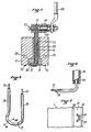
- - la figure 1 est une vue en perspective du dispositif de soudage et de perforation mis en place en regard d'un film,
- - la figure 2 est une vue en élévation partiellement interrompue du dispositif de soudage et de perforation selon l'invention,
- - la figure 3 est une vue en coupe partielle selon la ligne 111- 111 de la figure 2,
- - la figure 4 est une vue en coupe selon la ligne IV - IV de la figure 2, - la figure 5 est une vue en perspective agrandie du ruban de perforation,
- - la figure 6 est une vue en coupe encore agrandie selon la ligne VI - VI de la figure 5,
- - la figure 7 est une vue en plan du film à sa sortie du dispositif de soudage et de perforation selon l'invention.
- Des moyens de perforation généralement désignés en 8 sont portés par le support mobile 4 entre les parties chauffantes 7.1 des rubans de soudage 7.
- Selon le mode de réalisation préféré illustré, les moyens de perforation 8 sont montés sur un socle 9 qui est mobile parallèlement à la direction longitudinale des rubans de soudage 7. Plus précisément, le socle mobile 9 est disposé dans une ouverture 10 réalisée entre les rubans de soudage 7 et comportant des épaulements 11 et 12 sur lesquels prennent appui des épaulements correspondants du socle mobile 9. A la partie arrière du support mobile 4, l'ouverture 10 débouche selon une fente 13 dans laquelle passe une tige filetée 14 vissée à une de ses extrémités dans le socle mobile 9 et dont l'autre extrémité est reliée à un bouton molleté 15 prenant appui sur les bords de la fente 13 par l'intermédiaire d'une rondelle en matière plastique 16. Ainsi, lors du serrage du bouton molleté 15 le socle mobile 9 est bloqué en appui contre les épaulements 11 et 12, tandis que lors du desserrage du bouton molleté 15, le socle mobile 9 est libre de se déplacer dans l'ouverture 10 parallèlement aux rubans de soudage 7.
- Les moyens de perforation comprennent un ruban de perforation 17 chauffant par passage d'un courant électrique et présentant une nervure longitudinale 18 tournée vers le film. De préférence, le ruban de perforation 17 est un ruban profilé recourbé en forme de C et dont les extrémités sont repliées perpendiculairement au plan du ruban et engagées dans une première extrémité de tiges de liaison tubulaires 19 à laquelle elles sont soudées par une soudure 20. La seconde extrémité de chaque tige de liaison 19 est équipée d'un insert 21 soudé dans la tige de liaison.
- Pour recevoir les moyens de perforation, le socle 9 comporte des alésages 22 dans lesquels sont disposés des tubes électriquement isolants 23. Lorsque les tiges de liaison 19 sont engagées dans les tubes isolants 23, le ruban de perforation 17 s'appuie contre une plaque électriquement et thermiquement isolante 24 insérée dans la face frontale du socle mobile 9.
- Les inserts 21 situés aux extrémités des tiges de liaison 19 sont bloqués dans des cosses 25, elles-mimes disposées dans un bloc isolant 26, au moyen de vis de bloquage 27. Les cosses 25 sont reliées de façon conventionnelle à des câbles d'alimentation 28.
- Afin d'éviter un échauffement trop important de la tête de soudage et de perforation, on prévoit avantageusement dans la support mobile 4 des conduits 29 reliés à une source de fluide de refroidissement.
- Le fonctionnement du dispositif selon l'invention est le suivant: le film 1 est avancé pas à pas entre le support mobile 4 et la contreplaque 6. Pour chaque arrêt du film, le support mobile est avancé vers le film et un courant est envoyé dans les rubans de soudage 7 et le ruban de perforation 17. Au niveau du ruban de perforation 17, les parties latérales du ruban 17 effectuent une soudure tandis que la nervure 18 passe à travers les deux épaisseurs du film. Lorsque le film 1 a avancé d'un pas après le soudage et la perforation, il est de nouveau pressé par le support mobile 4 au niveau des parties froides 7.2 des rubans de soudage 7. Lors de cette étape, les soudures encore chaudes sont maintenues aplaties tout en étant refroidies, de sorte qu'à la sortie du dispositif le film comporte deux soudures planes 30 (figure 7) encadrant une languette 31 dans laquelle est formée une fente curviligne 32 en anse de panier elle-même entourée d'une soudure 33. On constate donc que lorsque le film 1 va être soudé transversalement lors d'une étape ultérieure, la languette 31 va être entièrement bordée par des soudures et ne permettra pas l'accumulation d'éléments polluants lors des différentes manipulations.
- Bien entendu, l'invention n'est pas limitée au mode de réalisation décrit ci-dessus et est susceptible de variantes de réalisation qui apparaîtront à l'homme de métier. En particulier, le ruban de perforation 17 peut être réalisé sous forme d'un anneau circulaire afin de réaliser une ouverture de même forme dans la languette, les tiges de liaison 19 étant alors soudées perpendiculairement à la face arrière de ranneau circulaire.
- On peut également prévoir de modifier à distance la position du socle mobile 9 afin d'éviter une intervention au niveau du dispositif de soudage et de perforation.
Claims (5)
Priority Applications (1)
| Application Number | Priority Date | Filing Date | Title |
|---|---|---|---|
| AT87903340T ATE50534T1 (de) | 1986-05-21 | 1987-05-20 | Vorrichtung zum schweissen un perforieren eines gefalteten films. |
Applications Claiming Priority (2)
| Application Number | Priority Date | Filing Date | Title |
|---|---|---|---|
| FR8607210 | 1986-05-21 | ||
| FR8607210A FR2598966B1 (fr) | 1986-05-21 | 1986-05-21 | Dispositif de soudage et de perforation d'un film thermoplastique replie sur lui-meme |
Publications (2)
| Publication Number | Publication Date |
|---|---|
| EP0267937A1 EP0267937A1 (fr) | 1988-05-25 |
| EP0267937B1 true EP0267937B1 (fr) | 1990-02-28 |
Family
ID=9335432
Family Applications (1)
| Application Number | Title | Priority Date | Filing Date |
|---|---|---|---|
| EP87903340A Expired - Lifetime EP0267937B1 (fr) | 1986-05-21 | 1987-05-20 | Dispositif de soudage et de perforation d'un film thermoplastique replie sur lui-meme |
Country Status (7)
| Country | Link |
|---|---|
| US (1) | US4946432A (fr) |
| EP (1) | EP0267937B1 (fr) |
| JP (1) | JPS63503371A (fr) |
| AU (1) | AU592443B2 (fr) |
| CA (1) | CA1291309C (fr) |
| FR (1) | FR2598966B1 (fr) |
| WO (1) | WO1987007212A2 (fr) |
Families Citing this family (8)
| Publication number | Priority date | Publication date | Assignee | Title |
|---|---|---|---|---|
| GB9103953D0 (en) * | 1991-02-26 | 1991-04-10 | Du Pont Canada | Insulated heat sealing jaw |
| US5538590A (en) * | 1991-02-26 | 1996-07-23 | Dupont Canada Inc. | Sealing element for packaging machines |
| DE4205583A1 (de) * | 1992-02-24 | 1993-08-26 | Windmoeller & Hoelscher | Schweissband |
| GB9210894D0 (en) * | 1992-05-21 | 1992-07-08 | Du Pont Canada | Heat sealing assembly for pouch-making packaging machines |
| US5472549A (en) * | 1994-07-08 | 1995-12-05 | Enclosure Technologies, Inc. | Apparatus for electronically seam fusing dissimilar polymeric materials |
| GB9804866D0 (en) * | 1998-03-07 | 1998-04-29 | Ceetak Developments Limited | Cutting and/or sealing sheet or roll plastics material |
| US6718735B2 (en) | 2002-03-19 | 2004-04-13 | Baxter International Inc. | Albumin in a flexible polymeric container |
| CN100464969C (zh) * | 2006-06-26 | 2009-03-04 | 山东新华医疗器械股份有限公司 | 非pvc膜焊接模具 |
Family Cites Families (36)
| Publication number | Priority date | Publication date | Assignee | Title |
|---|---|---|---|---|
| US2146308A (en) * | 1938-02-15 | 1939-02-07 | Stokes & Smith Co | Method of making packages |
| FR895084A (fr) * | 1942-03-16 | 1945-01-15 | Procédé et appareil de traitement des matières synthétiques par la chaleur et la pression | |
| US2606987A (en) * | 1949-06-14 | 1952-08-12 | Thomas W Winstead | Heat sealing element for thermo-plastic film |
| US2661741A (en) * | 1949-09-02 | 1953-12-08 | Hermac International Ltd | Fountain syringe bag |
| DE1673783U (de) * | 1951-04-11 | 1954-03-18 | Lorenz C Ag | Vorrichtung zur nahtverschweissung von thermoplastischen folien. |
| DE1673783B2 (de) * | 1958-12-01 | 1972-03-23 | S A des Ets Leon Hatot, Paris | Aus einer gleichstromquelle gespeiste alarmvorrichtung corzugs weise fuer elektrische uhren |
| US3183750A (en) * | 1961-09-19 | 1965-05-18 | Paramount Packaging Corp | Plastic bag cutter |
| US3299603A (en) * | 1962-03-12 | 1967-01-24 | Continental Can Co | Method of filling pouches |
| NL126868C (fr) * | 1962-11-14 | 1900-01-01 | ||
| US3272424A (en) * | 1965-01-11 | 1966-09-13 | Dow Chemical Co | Flexible container |
| US3367261A (en) * | 1965-08-16 | 1968-02-06 | Kashiwagi Kimifumi | Apparatus for continuous heat-sealing of thermoplastic sheets |
| DE1511036A1 (de) * | 1966-11-12 | 1969-10-02 | Gottlieb Wiedmann Kg Maschinen | Verfahren und Vorrichtung zum Herstellen von Taschen aus Kunststoff-Folie |
| US3538669A (en) * | 1968-10-07 | 1970-11-10 | Theodore H Gewecke | Method of preparing a packaged sterile solution |
| US3659777A (en) * | 1969-06-30 | 1972-05-02 | Takahi Kanada | Reinforced package |
| US3583460A (en) * | 1969-07-24 | 1971-06-08 | Union Carbide Corp | Sterile cover for fluid container port |
| FR2076245A5 (fr) * | 1970-01-07 | 1971-10-15 | Tabak Industriemaschinen | |
| US3720141A (en) * | 1970-04-08 | 1973-03-13 | Fmc Corp | Apparatus for making thermoplastic handle bags |
| US3982991A (en) * | 1971-11-13 | 1976-09-28 | Fr. Hesser Maschinenfabrik Ag | Device for welding and parting thermoplastic foils |
| SE351592C (sv) * | 1972-03-29 | 1974-05-06 | Iwema Foerpacknings Ab | Svetsbackar för sammansvetsning av foliebanor |
| US4010768A (en) * | 1974-11-04 | 1977-03-08 | Hechler Iv Valentine | Two-stage jet pump proportioner |
| FR2291010A1 (fr) * | 1974-11-15 | 1976-06-11 | Cellophane Sa | Dispositif de perforation en continu des films de matiere plastique |
| US3991297A (en) * | 1975-02-27 | 1976-11-09 | Bell Telephone Laboratories, Incorporated | Electrically heated soldering device |
| GB1556619A (en) * | 1975-07-03 | 1979-11-28 | Ici Ltd | Plastics bag |
| DE2633793A1 (de) * | 1976-07-28 | 1978-02-02 | Bosch Gmbh Robert | Beutelpackung mit grifflasche |
| GB1573374A (en) * | 1977-06-13 | 1980-08-20 | Verbecke H | Method of and apparatus for packaging a commodity in a pre formed plastics bag |
| JPS5844526B2 (ja) * | 1978-07-20 | 1983-10-04 | テンチ機械株式会社 | 熱封緘包装装置 |
| FR2460849A1 (fr) * | 1979-07-12 | 1981-01-30 | Seab | Perfectionnements aux recipients souples |
| GB2054451B (en) * | 1979-08-06 | 1983-12-14 | Roeder Ind Holdings | Making tubular plastics intermediate product and forming reclosable bags therefrom |
| US4306400A (en) * | 1980-02-07 | 1981-12-22 | Rexham Corporation | Packaging machine with continuous motion top sealer |
| FR2480243B1 (fr) * | 1980-04-09 | 1986-06-06 | Seab Sa | Recipient souple de conditionnement de produits |
| US4332327A (en) * | 1980-05-06 | 1982-06-01 | The Procter & Gamble Company | Accurately placed stress concentrating aperture in flexible packages |
| DE3102192C2 (de) * | 1981-01-23 | 1986-07-03 | Karl-Heinz Dr. 4802 Halle Sengewald | Tragetasche aus thermoplastischer Kunststoffolie |
| DE3149809A1 (de) * | 1981-12-16 | 1983-07-21 | Robert Bosch Gmbh, 7000 Stuttgart | Vorrichtung zum herstellen evakuierter beutelpackungen |
| FR2528801B1 (fr) * | 1982-06-22 | 1986-10-17 | Etude Applic Indle Brevets | Sachet souple pour l'ecoulement lent d'un milieu liquide, procede et machine pour le fabriquer |
| SE455859B (sv) * | 1982-08-26 | 1988-08-15 | Olov Erland Gustavsson | Sett och apparat for att forpacka elastiskt komprimerbara material |
| DE3408901A1 (de) * | 1984-03-10 | 1985-09-19 | Optima-Maschinenfabrik Dr. Bühler GmbH & Co, 7170 Schwäbisch Hall | Vorrichtung zum schweissen von folien |
-
1986
- 1986-05-21 FR FR8607210A patent/FR2598966B1/fr not_active Expired
-
1987
- 1987-05-20 AU AU74363/87A patent/AU592443B2/en not_active Ceased
- 1987-05-20 EP EP87903340A patent/EP0267937B1/fr not_active Expired - Lifetime
- 1987-05-20 WO PCT/FR1987/000174 patent/WO1987007212A2/fr not_active Ceased
- 1987-05-20 JP JP62503256A patent/JPS63503371A/ja active Pending
- 1987-05-21 CA CA000537673A patent/CA1291309C/fr not_active Expired - Lifetime
-
1989
- 1989-03-28 US US07/330,993 patent/US4946432A/en not_active Expired - Fee Related
Also Published As
| Publication number | Publication date |
|---|---|
| WO1987007212A3 (fr) | 1988-02-11 |
| FR2598966B1 (fr) | 1988-12-23 |
| WO1987007212A2 (fr) | 1987-12-03 |
| FR2598966A1 (fr) | 1987-11-27 |
| US4946432A (en) | 1990-08-07 |
| AU7436387A (en) | 1987-12-22 |
| EP0267937A1 (fr) | 1988-05-25 |
| CA1291309C (fr) | 1991-10-29 |
| JPS63503371A (ja) | 1988-12-08 |
| AU592443B2 (en) | 1990-01-11 |
Similar Documents
| Publication | Publication Date | Title |
|---|---|---|
| EP0267937B1 (fr) | Dispositif de soudage et de perforation d'un film thermoplastique replie sur lui-meme | |
| US4017351A (en) | System and device for inflating and sealing air inflated cushioning material | |
| EP1340060B1 (fr) | Procede de fabrication de convertisseurs thermo-electriques | |
| US4856989A (en) | Preheater for heat-sealing system for plastic containers | |
| CH428544A (fr) | Procédé et dispositif pour coller par la chaleur extrémités en recouvrement d'une bande en polymère orienté | |
| US5444964A (en) | Automatic package machine, and wrapping film fusing and sealing blade | |
| US3196068A (en) | Apparatus for welding thermoplastic sheet material | |
| EP0270586B1 (fr) | Dispositif de soudage d'un embout sur un film thermoplastique | |
| EP0705681A1 (fr) | Machine de thermosoudage | |
| US3937645A (en) | Heat sealing apparatus | |
| CH432812A (fr) | Procédé pour fixer une bande autour d'un objet | |
| US7323665B2 (en) | Heating element for high-speed film-sealing apparatus, and method for making same | |
| FR2598962A1 (fr) | Conformateur de film souple equipe d'embouts en saillie | |
| FR2690377A1 (fr) | Dispositif pour la soudure de bandes de feuille en matière thermoplastique. | |
| US3660205A (en) | Device for continuously sealing and severing edges of folded film | |
| US3901759A (en) | Plastics web slitting and sealing device | |
| US3466979A (en) | Apparatus and method for transverse heat-sealing plastic webbing | |
| FR2690412A1 (fr) | Dispositif d'emballage d'un paquet d'objets à l'aide d'un film en matériau plastique. | |
| US6539692B1 (en) | Form, fill and seal container forming apparatus | |
| EP0095498A1 (fr) | Soudage thermique de materiaux thermoplastiques | |
| FR2540847A1 (fr) | Procede et dispositif de reliage de rubans ou bandes de tissu decoupe | |
| FR2482898A1 (fr) | Ensemble d'electrode pour le soudage des matieres thermoplastiques | |
| EP1465764A1 (fr) | Machine a fabriquer des coussins d'air pour l'emballage a partir d'un film tubulaire dispose sur une bobine | |
| JPS6249851B2 (fr) | ||
| JPH056105Y2 (fr) |
Legal Events
| Date | Code | Title | Description |
|---|---|---|---|
| PUAI | Public reference made under article 153(3) epc to a published international application that has entered the european phase |
Free format text: ORIGINAL CODE: 0009012 |
|
| 17P | Request for examination filed |
Effective date: 19880112 |
|
| AK | Designated contracting states |
Kind code of ref document: A1 Designated state(s): AT BE CH DE GB IT LI LU NL SE |
|
| 17Q | First examination report despatched |
Effective date: 19890605 |
|
| RAP1 | Party data changed (applicant data changed or rights of an application transferred) |
Owner name: BAXTER INTERNATIONAL INC. (A DELAWARE CORPORATION) |
|
| GRAA | (expected) grant |
Free format text: ORIGINAL CODE: 0009210 |
|
| AK | Designated contracting states |
Kind code of ref document: B1 Designated state(s): AT BE CH DE GB IT LI LU NL SE |
|
| PG25 | Lapsed in a contracting state [announced via postgrant information from national office to epo] |
Ref country code: IT Free format text: LAPSE BECAUSE OF FAILURE TO SUBMIT A TRANSLATION OF THE DESCRIPTION OR TO PAY THE FEE WITHIN THE PRE;WARNING: LAPSES OF ITALIAN PATENTS WITH EFFECTIVE DATE BEFORE 2007 MAY HAVE OCCURRED AT ANY TIME BEFORE 2007. THE CORRECT EFFECTIVE DATE MAY BE DIFFERENT FROM THE ONE RECORDED.SCRIBED TIME-LIMIT Effective date: 19900228 Ref country code: AT Effective date: 19900228 Ref country code: NL Effective date: 19900228 |
|
| REF | Corresponds to: |
Ref document number: 50534 Country of ref document: AT Date of ref document: 19900315 Kind code of ref document: T |
|
| REF | Corresponds to: |
Ref document number: 3761751 Country of ref document: DE Date of ref document: 19900405 |
|
| PG25 | Lapsed in a contracting state [announced via postgrant information from national office to epo] |
Ref country code: LU Free format text: LAPSE BECAUSE OF NON-PAYMENT OF DUE FEES Effective date: 19900531 |
|
| GBT | Gb: translation of ep patent filed (gb section 77(6)(a)/1977) | ||
| NLV1 | Nl: lapsed or annulled due to failure to fulfill the requirements of art. 29p and 29m of the patents act | ||
| PLBE | No opposition filed within time limit |
Free format text: ORIGINAL CODE: 0009261 |
|
| STAA | Information on the status of an ep patent application or granted ep patent |
Free format text: STATUS: NO OPPOSITION FILED WITHIN TIME LIMIT |
|
| 26N | No opposition filed | ||
| EAL | Se: european patent in force in sweden |
Ref document number: 87903340.5 |
|
| PGFP | Annual fee paid to national office [announced via postgrant information from national office to epo] |
Ref country code: GB Payment date: 19960325 Year of fee payment: 10 |
|
| PGFP | Annual fee paid to national office [announced via postgrant information from national office to epo] |
Ref country code: SE Payment date: 19960326 Year of fee payment: 10 |
|
| PGFP | Annual fee paid to national office [announced via postgrant information from national office to epo] |
Ref country code: BE Payment date: 19960425 Year of fee payment: 10 |
|
| PGFP | Annual fee paid to national office [announced via postgrant information from national office to epo] |
Ref country code: CH Payment date: 19960429 Year of fee payment: 10 |
|
| PGFP | Annual fee paid to national office [announced via postgrant information from national office to epo] |
Ref country code: DE Payment date: 19960628 Year of fee payment: 10 |
|
| PG25 | Lapsed in a contracting state [announced via postgrant information from national office to epo] |
Ref country code: GB Effective date: 19970520 |
|
| PG25 | Lapsed in a contracting state [announced via postgrant information from national office to epo] |
Ref country code: SE Effective date: 19970521 |
|
| PG25 | Lapsed in a contracting state [announced via postgrant information from national office to epo] |
Ref country code: LI Free format text: LAPSE BECAUSE OF NON-PAYMENT OF DUE FEES Effective date: 19970531 Ref country code: CH Free format text: LAPSE BECAUSE OF NON-PAYMENT OF DUE FEES Effective date: 19970531 Ref country code: BE Effective date: 19970531 |
|
| BERE | Be: lapsed |
Owner name: BAXTER INTERNATIONAL INC. (A DELAWARE CORP.) Effective date: 19970531 |
|
| GBPC | Gb: european patent ceased through non-payment of renewal fee |
Effective date: 19970520 |
|
| REG | Reference to a national code |
Ref country code: CH Ref legal event code: PL |
|
| EUG | Se: european patent has lapsed |
Ref document number: 87903340.5 |
|
| PG25 | Lapsed in a contracting state [announced via postgrant information from national office to epo] |
Ref country code: DE Free format text: LAPSE BECAUSE OF NON-PAYMENT OF DUE FEES Effective date: 19980203 |