EP0268018A2 - Commande à quatre quadrants avec un moteur à courant continu - Google Patents
Commande à quatre quadrants avec un moteur à courant continu Download PDFInfo
- Publication number
- EP0268018A2 EP0268018A2 EP87111379A EP87111379A EP0268018A2 EP 0268018 A2 EP0268018 A2 EP 0268018A2 EP 87111379 A EP87111379 A EP 87111379A EP 87111379 A EP87111379 A EP 87111379A EP 0268018 A2 EP0268018 A2 EP 0268018A2
- Authority
- EP
- European Patent Office
- Prior art keywords
- motor
- power
- adjustors
- quadrant
- series
- Prior art date
- Legal status (The legal status is an assumption and is not a legal conclusion. Google has not performed a legal analysis and makes no representation as to the accuracy of the status listed.)
- Withdrawn
Links
Images
Classifications
-
- H—ELECTRICITY
- H02—GENERATION; CONVERSION OR DISTRIBUTION OF ELECTRIC POWER
- H02P—CONTROL OR REGULATION OF ELECTRIC MOTORS, ELECTRIC GENERATORS OR DYNAMO-ELECTRIC CONVERTERS; CONTROLLING TRANSFORMERS, REACTORS OR CHOKE COILS
- H02P7/00—Arrangements for regulating or controlling the speed or torque of electric DC motors
- H02P7/06—Arrangements for regulating or controlling the speed or torque of electric DC motors for regulating or controlling an individual DC dynamo-electric motor by varying field or armature current
- H02P7/18—Arrangements for regulating or controlling the speed or torque of electric DC motors for regulating or controlling an individual DC dynamo-electric motor by varying field or armature current by master control with auxiliary power
- H02P7/24—Arrangements for regulating or controlling the speed or torque of electric DC motors for regulating or controlling an individual DC dynamo-electric motor by varying field or armature current by master control with auxiliary power using discharge tubes or semiconductor devices
- H02P7/28—Arrangements for regulating or controlling the speed or torque of electric DC motors for regulating or controlling an individual DC dynamo-electric motor by varying field or armature current by master control with auxiliary power using discharge tubes or semiconductor devices using semiconductor devices
- H02P7/281—Arrangements for regulating or controlling the speed or torque of electric DC motors for regulating or controlling an individual DC dynamo-electric motor by varying field or armature current by master control with auxiliary power using discharge tubes or semiconductor devices using semiconductor devices the DC motor being operated in four quadrants
-
- H—ELECTRICITY
- H02—GENERATION; CONVERSION OR DISTRIBUTION OF ELECTRIC POWER
- H02P—CONTROL OR REGULATION OF ELECTRIC MOTORS, ELECTRIC GENERATORS OR DYNAMO-ELECTRIC CONVERTERS; CONTROLLING TRANSFORMERS, REACTORS OR CHOKE COILS
- H02P7/00—Arrangements for regulating or controlling the speed or torque of electric DC motors
- H02P7/03—Arrangements for regulating or controlling the speed or torque of electric DC motors for controlling the direction of rotation of DC motors
- H02P7/05—Arrangements for regulating or controlling the speed or torque of electric DC motors for controlling the direction of rotation of DC motors by means of electronic switching
Definitions
- the invention relates to a four-quadrant drive with a DC motor according to the preamble of patent claim 1.
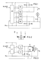
- FIG. 1 A corresponding known arrangement is illustrated in FIG. 1.
- a controller driver circuit A10 with a setpoint input for the manipulated variable "motor current" I M is provided.
- a speed or position control can also be set up by superimposed circles.
- the controller-driver circuit A10 controls four power controllers V10, V20, V30, V40 so that the motor M, depending on the direction of rotation, via the power controllers V10 and V40 or V20 and V30 is on the input or output side of the supply voltage. Free-wheeling diodes V50 to V80 are also required.
- One power controller, the motor and the second power controller are connected in series. Viewed overall, this results in a considerable amount of tax, a large installation volume and also a considerable power or voltage loss at the two power controllers connected in series with the M motor.
- the object of the invention is to provide a four-quadrant drive of the type mentioned, in which the overall structure is simplified and the effort for the control and in particular the losses in the power controllers are significantly reduced.
- the design according to the invention considerably reduces the expenditure in power electronics and protection, the volume of the power electronics and the power loss compared to the known construction. As a result, since only one power controller is connected to the motor in series, there is less loss of voltage or a larger voltage reserve for the operation of the motor. This is particularly important for low supply voltages such as those found in vehicles - for example 24 V -.
- the envisaged series reversing motor M contains two field windings L1, L2, both of which (here internal to the motor) are connected to the armature winding of the motor. Depending on which of the two field windings L1 or L2 the (larger) motor current is impressed, clockwise or counterclockwise rotation takes place.
- Each field winding L1 or L2 is connected via a power controller V1 or V2 controlled by a regulator driver circuit A1 with setpoint input, for example to the positive pole of the supply voltage.
- the second armature connection is then at the OV potential.
- the assignment of the positive pole and the OV potential of the supply voltage can also be exchanged without affecting the function if the polarity of the covered elements is taken into account.
- the controller driver circuit determines the size and direction of the torque of the motor via the power controller.
- V2 When actuated via V2, L2, a moment is generated in the opposite direction.
- the motor current I M detected by the sensors R 1 and R 2 follows the reference variable given the setpoint input.
- the additional effort for the second field winding L2 of the motor M results in considerable advantages in comparison with the known embodiment according to FIG. 1.
- the number of power semiconductors and free-wheeling diodes is halved, so that only a reduced number of these elements from 4 to 2 is required.
- the installation volume is reduced due to the elimination of the power semiconductors and the associated ones Heatsink.
- the power loss is reduced because only one power semiconductor is required per direction of rotation and the voltage available to the motor is higher than that of a bridge circuit by the voltage drop across a power semiconductor, which can be a few V at least.
Landscapes
- Engineering & Computer Science (AREA)
- Power Engineering (AREA)
- Control Of Eletrric Generators (AREA)
- Control Of Direct Current Motors (AREA)
- Control Of Multiple Motors (AREA)
Applications Claiming Priority (2)
| Application Number | Priority Date | Filing Date | Title |
|---|---|---|---|
| DE3639197 | 1986-11-15 | ||
| DE3639197 | 1986-11-15 |
Publications (2)
| Publication Number | Publication Date |
|---|---|
| EP0268018A2 true EP0268018A2 (fr) | 1988-05-25 |
| EP0268018A3 EP0268018A3 (fr) | 1988-11-30 |
Family
ID=6314106
Family Applications (1)
| Application Number | Title | Priority Date | Filing Date |
|---|---|---|---|
| EP87111379A Withdrawn EP0268018A3 (fr) | 1986-11-15 | 1987-08-06 | Commande à quatre quadrants avec un moteur à courant continu |
Country Status (2)
| Country | Link |
|---|---|
| EP (1) | EP0268018A3 (fr) |
| NO (1) | NO873323D0 (fr) |
Cited By (1)
| Publication number | Priority date | Publication date | Assignee | Title |
|---|---|---|---|---|
| RU2352052C2 (ru) * | 2006-12-27 | 2009-04-10 | Государственное образовательное учреждение высшего профессионального образования "Южно-Российский государственный технический университет (Новочеркасский политехнический институт)" | Реверсивный электропривод постоянного тока с двигателем последовательного возбуждения (варианты) |
Family Cites Families (3)
| Publication number | Priority date | Publication date | Assignee | Title |
|---|---|---|---|---|
| AT282003B (de) * | 1966-11-28 | 1970-06-10 | Lansing Bagnall Ltd | Schaltungsanordnung eines an einen von einem Steuerimpulsgenerator ventilgesteuerten Gleichstromsteller angeschlossenen, mit zwei Feldwicklungen zur Drehrichtungsumkehr ausgebildeten Serienschlußmotors |
| JPS5262616A (en) * | 1975-11-19 | 1977-05-24 | Hitachi Ltd | Electric car braking controller |
| US4384240A (en) * | 1980-03-18 | 1983-05-17 | Technical Operations Limited | Regenerative braking system for three-terminal d.c. motor |
-
1987
- 1987-08-06 EP EP87111379A patent/EP0268018A3/fr not_active Withdrawn
- 1987-08-10 NO NO873323A patent/NO873323D0/no unknown
Cited By (1)
| Publication number | Priority date | Publication date | Assignee | Title |
|---|---|---|---|---|
| RU2352052C2 (ru) * | 2006-12-27 | 2009-04-10 | Государственное образовательное учреждение высшего профессионального образования "Южно-Российский государственный технический университет (Новочеркасский политехнический институт)" | Реверсивный электропривод постоянного тока с двигателем последовательного возбуждения (варианты) |
Also Published As
| Publication number | Publication date |
|---|---|
| NO873323D0 (no) | 1987-08-10 |
| EP0268018A3 (fr) | 1988-11-30 |
Similar Documents
| Publication | Publication Date | Title |
|---|---|---|
| DE60215095T2 (de) | Motorantrieb und System | |
| EP0356791B1 (fr) | Système d'entraînement, en particulier pour les installations d'essuie-glace de véhicule automobile | |
| EP1583676B1 (fr) | Dispositif d'activation pour systemes d'essuie-glace bimoteurs | |
| DE3433886A1 (de) | Steuereinrichtung fuer einen gleichstrom-halbleitersteller | |
| DE4138194A1 (de) | Verfahren und vorrichtung zur erfassung der position und bewegungsrichtung translatorisch und/oder rotatorisch bewegter aggregate | |
| DE60314288T2 (de) | Motorantriebsvorrichtung, von derselben vorrichtung angetriebener motor und vorrichtung für den gebrauch desselben motors | |
| DE3226549A1 (de) | Motorantrieb mit wahlweiser parallel- und serienschaltung | |
| DE69206503T2 (de) | Hochgeschwindigkeits-gleichstrommotor. | |
| EP0268018A2 (fr) | Commande à quatre quadrants avec un moteur à courant continu | |
| DE2313706A1 (de) | Servolenkung | |
| EP0076359B1 (fr) | Dispositif de propulsion avec deux moteurs entraînés dans des directions opposées pour compenser le jeu des réducteurs | |
| DE3411001C2 (fr) | ||
| DE2126132A1 (de) | Elektronischer Schalter zum Abbremsen von Gleichstrommotoren in Antriebssystemen für optische Apparate und Geräte | |
| EP1934486B1 (fr) | Module ventilateur de radiateur pour un vehicule a moteur | |
| DE4429998A1 (de) | Anordnung zur Positionssteuerung von Elektromotoren | |
| EP0802613A3 (fr) | Moteur à courant continu sans balai, multiphase | |
| DE3919952A1 (de) | Motorstromregelung fuer einen buerstenlosen gleichstrommotor | |
| DE3719777A1 (de) | Antrieb, insbesondere fuer wischanlagen an kraftfahrzeugen | |
| DE3315664A1 (de) | Steuerschaltung zur drehzahlregelung eines gleichstrommotors | |
| EP0347705B1 (fr) | Appareil d'entraînement pour une chariot portique | |
| DE102008019546A1 (de) | Motorpumpenaggregat für Kraftfahrzeugbremsenregelungssysteme | |
| DE3827882A1 (de) | Anordnung zum stellrichtungs- und stellwegabhaengigen ansteuern eines stellgliedes | |
| EP0303213A2 (fr) | Circuit pour la régulation de vitesse d'un moteur à courant continu commuté électroniquement | |
| DE1438020A1 (de) | Anordnung zur Speisung eines Gleichstrom-Reihenschlussmotors ueber tastbare Ventile | |
| DE10237434A1 (de) | Spannungsversorgung für Elektromotoren und Elektromotor, sowie Stellantrieb für diese Spannungsversorgung |
Legal Events
| Date | Code | Title | Description |
|---|---|---|---|
| PUAI | Public reference made under article 153(3) epc to a published international application that has entered the european phase |
Free format text: ORIGINAL CODE: 0009012 |
|
| AK | Designated contracting states |
Kind code of ref document: A2 Designated state(s): CH DE FR GB LI SE |
|
| PUAL | Search report despatched |
Free format text: ORIGINAL CODE: 0009013 |
|
| AK | Designated contracting states |
Kind code of ref document: A3 Designated state(s): CH DE FR GB LI SE |
|
| RHK1 | Main classification (correction) |
Ipc: H02P 7/28 |
|
| STAA | Information on the status of an ep patent application or granted ep patent |
Free format text: STATUS: THE APPLICATION IS DEEMED TO BE WITHDRAWN |
|
| 18D | Application deemed to be withdrawn |
Effective date: 19890531 |
|
| RIN1 | Information on inventor provided before grant (corrected) |
Inventor name: SCHOROTH, ANNO |