EP0268151A1 - Procédé et dispositif de scellage des rabats de pliage d'un emballage - Google Patents
Procédé et dispositif de scellage des rabats de pliage d'un emballage Download PDFInfo
- Publication number
- EP0268151A1 EP0268151A1 EP87116274A EP87116274A EP0268151A1 EP 0268151 A1 EP0268151 A1 EP 0268151A1 EP 87116274 A EP87116274 A EP 87116274A EP 87116274 A EP87116274 A EP 87116274A EP 0268151 A1 EP0268151 A1 EP 0268151A1
- Authority
- EP
- European Patent Office
- Prior art keywords
- sealing
- packs
- folding
- tabs
- region
- Prior art date
- Legal status (The legal status is an assumption and is not a legal conclusion. Google has not performed a legal analysis and makes no representation as to the accuracy of the status listed.)
- Granted
Links
Images


Classifications
-
- B—PERFORMING OPERATIONS; TRANSPORTING
- B65—CONVEYING; PACKING; STORING; HANDLING THIN OR FILAMENTARY MATERIAL
- B65B—MACHINES, APPARATUS OR DEVICES FOR, OR METHODS OF, PACKAGING ARTICLES OR MATERIALS; UNPACKING
- B65B51/00—Devices for, or methods of, sealing or securing package folds or closures; Devices for gathering or twisting wrappers, or necks of bags
- B65B51/10—Applying or generating heat or pressure or combinations thereof
- B65B51/14—Applying or generating heat or pressure or combinations thereof by reciprocating or oscillating members
Definitions
- the invention relates to a method and an apparatus for sealing folding tabs of a pack (cigarette pack) encased in a sealable blank with the aid of heated sealing elements which can be pressed against the tabs in the area of the folding tabs during a standstill phase (sealing cycle).
- the problem with fast-running packaging machines is that within the available, besides short sealing times (sealing cycle) the welding of the folding flaps should be carried out in such a way that they are connected as precisely and tightly as possible, but the packaging material and the packaging itself are not affected.
- the cycle times for packaging machines for cigarette packs are extremely short.
- the sealing of the outer covering made of plastic films (polyethylene etc.) must be carried out precisely within a very short time.
- the present invention is primarily concerned with the completion and sealing of such outer wrappers of cigarette packs.
- the task on which the invention is based is to carry out the sealing of folding flaps precisely and gently within the shortest sealing cycle times, with an increased tightness of the sealing.
- the method according to the invention is characterized in that at least the transfer of heat to the folding tab between the sealing acts is maintained during the transport of the packs.
- the sealing elements in particular sealing jaws
- a certain contact of the sealing jaws or of sealing surfaces thereof with the folding tabs is also achieved in the Maintain time between the sealing cycles, i.e. also during the further transport of the packages.
- the sealing jaws perform only very small strokes in the invention, namely of approximately 1 mm. This not only results in a reduction in the time when the sealing jaws are actuated, but rather the packs with the sealed folding tabs slide during further transport with light touch along the sealing surfaces of the sealing jaws. As a result, smoothing and resealing also takes place during further movement.
- the first folded folding flaps are pre-sealed.
- an internal longitudinal flap is attached by pre-sealing to cut parts that have also already been folded and are partially located under the longitudinal flap.
- the outer wrappings of cigarette packs are usually folded so that a tube overlap is formed in the area of a narrow side surface.
- the partially overlapping tubular flaps are sealed according to the invention in the region of an upward conveying path, namely by a sealing unit which is common to several superimposed packs and which also has a short stroke (approx. 1 mm) Side faces of the packs are deliverable.
- a sealing unit which is common to several superimposed packs and which also has a short stroke (approx. 1 mm)
- Side faces of the packs are deliverable.
- the smoothing, resealing effect of the sealing jaw comes into effect during the transport of the packs.
- sealing jaws are arranged on both sides of the packing track and extend over a dimension of a plurality of packs lying next to one another in the conveying direction, preferably two packs each being arranged one above the other.
- the sealing jaws are provided with limited sealing ridges, each of which is assigned to an end face of a pack and have the effect that the sealing face is effective at a short distance from the edge of the end face.
- the dimensionally stable, largely rigid edges on the edge of the end faces are therefore not subjected to pressure by the sealing elements.
- the device described below is used for (ready) folding and sealing packs 10 for cigarettes, the preferred area of application. In detail, it is about hinge-lid packs.
- These relatively dimensionally stable packs 10 are provided with an outer covering made of a sealable film (polyethylene film). Folding flaps of the same are fixed by sealing. It is now a matter of connecting these retaining tabs as precisely and, above all, as possible.
- the outer wrapping of the packs 10 is designed in the present embodiment in such a way that, as is known in packaging technology, a corresponding film cut is first placed in a U-shape around the pack 10, in such a way that in the region of a narrow side face 11 of the pack partially overlapping tube tabs (not shown) arise. These are to be connected to one another over the full length of the side surface 11 by sealing.
- folding flaps arise in the area of (upper and lower) end faces 12 and 13 of the packs 10.
- the parts of the outer wrapping which initially protrude over the pack 10 are folded in an envelope-like manner such that (first folded) side flaps 14 and 15 arise, which are folded from the narrow side surfaces 11 against the end face 12, 13.
- Trapezoidal inner longitudinal tabs 16 and outer longitudinal tabs 17 are folded one after the other, starting from the front and back of the pack 10.
- the side tabs 14, 15 and the partially overlapping longitudinal tabs 16, 17 are also to be connected to one another by sealing.
- the packs 10 with the already partially folded outer wrapper are fed on a lower conveyor track 18 to the device shown here.
- a support plate 19 there are lateral folding members, namely folding thumb 20 and folding switches 21, by means of which the side flaps 14 lying at the front in the conveying direction and then the lower, inner longitudinal flaps 16 are folded.
- the rear side tab 15 in the conveying direction is already folded before the pack 10 reaches the area of the support plate 19.
- the folding elements described and the sequence of folding are also known in packaging technology.
- the pack 10 is conveyed on the support plate 19 into the region of a lifting jack 22 that can be moved up and down.
- the exact position of the packs 10 in the conveying direction is determined by a position stop 23 arranged on the support plate 19.
- the lifting device conveys the packs 10 individually and successively into an upright conveyor tower 24.
- the latter can be provided with a recess in the area below the conveyor tower 24 or - as in the present exemplary embodiment - from a total of two lateral ones , there are spaced-apart support rails 25, 26.
- the jack 22 can be moved between them.
- the conveyor tower 24 consists of two lateral, opposite guide walls 27, 28 which extend in the region of the laterally directed end faces 12, 13 of the packs 10.
- the guide walls 27, 28 or their lower edge 29 also have the function of a folding member.
- Support fingers 30, 31 are provided as the lower support members for the packs 10 lying one above the other in the conveyor tower 24, which can be introduced from the sides of the guide walls 27, 28 by transverse movement into the region of the conveyor tower 24, in such a way that the respective lower pack 10 on the front sides Ends held and worn.
- the horizontal support fingers 30, 31 in the carrying position are attached to U-shaped support arms 32 which are pivotally mounted such that the pivot fingers 30, 31 move by pivoting movements into or out of the region of the conveyor tower 24 can be withdrawn, the latter for the introduction of a subsequent pack 10. In this process, the packs 10 already in the conveyor tower 24 are raised by the size of a pack 10.
- the packs 10 arrive in the area of a horizontal pack track 33.
- This essentially consists of a lower, central support rail 34 with a smaller width than the dimension of the transverse packs 10. These are conveyed in a sliding manner on the support rail 34 in cycles.
- Fixed side walls 35, 36 are arranged in a partial area of the packing web 33.
- the top of the packs 10 lying one above the other in pairs is also guided.
- Two upright guide webs 37, 38 spaced apart from one another extend adjacent to the end faces 12, 13 of the packs 10 on the upper side thereof in the conveying direction.
- a brush 39 extending over a longer area of the packing web 33 is arranged as a counter-sliding body for the upper layer of the packing 10.
- the packs 10 lying one above the other in pairs are moved further in the area of the pack track 33 by a slide 40 which can be moved back and forth in the horizontal plane. This grips the two upper packs 10 within the conveyor tower 24 and moves them in the conveying direction shown on the packing track 33 or the support rail 34.
- the folding tabs of the outer covering namely the tubular tabs formed on the side surface 11 and the fold lobes 14..17 in the area of the end faces 12 and 13 are connected to one another after their completion by sealing, that is to say by applying heat and pressure.
- the tubular flaps are sealed on the side surface 11 in the region of the conveyor tower 24.
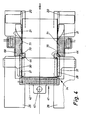
- a sealing member in the form of an upright sealing jaw 41. This extends over the full length of the side surfaces 11 and thus over the full width of the conveyor tower 24 (FIG. 4) and over a height of several - in the present case four - packs 10 within the conveyor tower 24.
- the essentially plate-shaped sealing jaw 41 is equipped with (electrical) heating cartridges 42. The sealing jaw 41 can be moved transversely to the packs 10 or to the side faces 11 thereof via an actuating rod 43 attached to the free rear side.
- the sealing jaw 41 performs a sealing cycle in each case during the standstill phases of the packs 10 in the conveyor tower 24, and is therefore pressed (briefly) against the side surfaces 11.
- the upward movement of the packings 10, that is to say the conveying cycle, takes place during a withdrawn, relieving position of the sealing jaw 41. However, this is only slightly lifted from the side surfaces 11 during the transport movement of the packs 10.
- the (pulsating) stroke of the sealing jaw 41 is approximately 1 mm. Taking into account a certain deformability of the packs 10, it follows that they also rest against the latter during the conveying movement, that is to say when the sealing jaw 41 is withdrawn.
- the sealing jaw 41 thereby smoothes the film or the tubular flaps and also continues the sealing.
- the packs 10 which enter the area of the (horizontal) packing track 33 one after the other are sealed with respect to their tubular tabs.
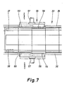
- sealing members are arranged in the region of the packing web 33 on both sides thereof.
- one sealing jaw 45, 46 with heating cartridges 47 extends as a lateral boundary of the packing web 33 over a length of several packs 10 in the conveying direction - in the present case over three pairs.
- the height of the sealing jaws 45, 46 corresponds to the height of the two packs 10 one above the other.
- the sealing jaws 45, 46 extend into the area above the conveyor tower 24, so that the packs 10 moving upward, when leaving the conveyor tower 24, enter directly between the sealing jaws 45 and 46 provided with a lower running-in phase in this area. The sealing therefore begins during the upward movement.
- the sealing jaws 45, 46 are designed in a special way in the region adjoining the conveying direction of the packing web 33, namely provided on the sides facing the packs 10 (end faces 12, 13) with elevations 48, 49 which form the actual sealing surfaces 50.
- the elevations 48, 49 or their sealing surface 50 have a smaller dimension (width and height) than the end faces 12, 13 of the packs 10. This ensures that the elevations 48, 49 with their sealing surfaces 50 are not in the region of the dimensionally stable edges of the Packs of 10 fit.
- the increases 48, 49 are provided with bevels 51, 52 all around.
- the (upright) chamfer 52 on the inlet side of the packs 10 in the region of the elevations 48, 49 is elongated and designed to run out at an angle, so that trouble-free entry is ensured.
- the sealing jaws 45, 46 are also moved in cycles against the assigned (six) packs 10 while exerting the required sealing pressure. This sealing cycle takes place during the standstill phase of the packings 10. For the further transport of the same, the sealing jaws 45, 46 are lifted slightly from the end faces 12, 13 (stroke about 1 mm). It is thereby achieved that the packs 10 can be moved further without interference, but whose end faces 12, 13 or their folding tabs 14, 17 continue to slide against the sealing surfaces 50. Therefore, heat and (lower) pressure is transferred during the conveyance, which has a smoothing effect on the folding tabs.
- actuating rods 53 are attached to the sealing jaws and are acted upon by a suitable actuating member (pressure medium cylinder).
- the sealed packs 10 emerging from the area of the sealing jaws 45, 46 pass through a section of the cooling and stabilization of the sealing in the area of the packing track 33.
- the packs 10 are guided laterally through the fixed side walls 35, 36 of the packaging web 33. This is followed by a station in which the packs are detached from one another during the standstill by transverse relative movement, provided that the seals of adjacent packs have bonded to one another. Both the packs lying one above the other are shifted relative to each other as also adjacent pairs of packs.
- specially shaped sliding plates 55 and 56 which can be moved transversely to the conveying direction, are arranged laterally next to the packing web 33. These come to rest on the end faces 12 and 13 of two successive pairs of packs 10 during the standstill phase.
- the displacement plates 55, 56 can be moved back and forth via plungers 57.
- the printing surfaces facing the packs 10 are designed in a special way.
- One displacement plate 55 is provided with a shoulder-shaped double projection 58 in the area rearward in the conveying direction and then with a recess 59 thereafter in the conveying direction.
- the double projection 58 also forms an offset 60 in height, so that two pressure surfaces 61, 62 are arranged offset from one another in this region, each of which is assigned to one of the packs 10 lying one above the other (FIGS. 8 and 9).
- the sliding plate 56 on the opposite side of the packing web 33 is designed accordingly.
- the displacement plate 56 is accordingly provided with a double recess 54, which likewise has two pressure surfaces 63 and 64, which are separated from one another by an offset 65. This is formed in the opposite direction to the offset 60, so that the pressure surface 61 projects, the opposite pressure surface 63, however, is arranged in a recessed plane.
- the printing surface 62 is set back, while the printing surface 64 projects accordingly.
- a region of the displacement plates 55, 56 which follows in the conveying direction has an aligning function for the packs which have been displaced relative to one another in the preceding work cycle.
- the sliding plate 55 is provided in this area with a recess 59, which is smooth over the full height (two packs) or has a shoulder, but is set back both against the pressure surface 61 and against the pressure surface 62.
- the sliding plate 56 is provided with a projection 66, which is also designed with a smooth surface or without a shoulder.
- the individual surfaces of the different areas of the sliding plates 55, 56 are coordinated in their position so that during a working stroke of the sliding plates 55, 56 to each other or against the end faces of the packs in the area of the double projection 58 and the double recess 54, the two superimposed packs both can be moved against each other as well as relative to the adjacent packs (position according to FIG. 8).
- the packs previously brought into this relative position in the area of recess 59 and projection 66 are displaced relative to one another in such a way that they are aligned again.
- the two packs are aligned with the packing web 33 and thus with the packs being conveyed onward.
- the device is provided with devices for pre-sealing the folding tabs in the area of the end faces 12, 13, so that before the folding is completed the first folded rags are fixed in their position.
- the first folded inner longitudinal tab 16 This is sealed to the previously folded side tabs 14, 15 by two sealing points 67, 68.
- the rectangular sealing points 67, 68 are produced by sealing elements which are arranged in the region of the conveyor track 18 on both sides thereof.
- the folding switches 21 as a lateral boundary of the conveyor track 18 are provided with passages 69 in the form of an elongated opening. Sealing elements, namely two sealing pins 70, 71 pass through these to the end faces 12, 13 of the packs 10 and thus to the (triangular) region of the longitudinal tabs 16.
- the heated sealing pins 70, 71 are arranged on a common holder 72 in the form of a two-armed, pivotable lever. This is actuated by a rotating cam 73 (cup curve) via a feeler roller 74.
- the sealing pins 70, 71 also perform a relatively short working stroke.
- the sealing pins 70, 71 are moved into a clearly retracted position (dash-dotted lines in FIG. 5) by a pneumatic cylinder 75, the piston rod of which acts on the holder 72 in a lifting sense via a transfer roller 76.
Landscapes
- Engineering & Computer Science (AREA)
- Mechanical Engineering (AREA)
- Wrapping Of Specific Fragile Articles (AREA)
- Package Closures (AREA)
- Basic Packing Technique (AREA)
- Auxiliary Devices For And Details Of Packaging Control (AREA)
- Closing Of Containers (AREA)
Applications Claiming Priority (2)
| Application Number | Priority Date | Filing Date | Title |
|---|---|---|---|
| DE19863638627 DE3638627A1 (de) | 1986-11-12 | 1986-11-12 | Verfahren und vorrichtung zum siegeln von faltlappen einer packung |
| DE3638627 | 1986-11-12 |
Publications (2)
| Publication Number | Publication Date |
|---|---|
| EP0268151A1 true EP0268151A1 (fr) | 1988-05-25 |
| EP0268151B1 EP0268151B1 (fr) | 1992-06-03 |
Family
ID=6313769
Family Applications (1)
| Application Number | Title | Priority Date | Filing Date |
|---|---|---|---|
| EP87116274A Expired - Lifetime EP0268151B1 (fr) | 1986-11-12 | 1987-11-05 | Procédé et dispositif de scellage des rabats de pliage d'un emballage |
Country Status (6)
| Country | Link |
|---|---|
| US (1) | US4843800A (fr) |
| EP (1) | EP0268151B1 (fr) |
| JP (1) | JPH0784209B2 (fr) |
| BR (1) | BR8706089A (fr) |
| CA (1) | CA1325377C (fr) |
| DE (2) | DE3638627A1 (fr) |
Cited By (1)
| Publication number | Priority date | Publication date | Assignee | Title |
|---|---|---|---|---|
| ITTO20120385A1 (it) * | 2012-04-30 | 2013-10-31 | Opm S P A | Metodo e macchina per piegare alette termosaldate alle estremita' di confezioni |
Families Citing this family (20)
| Publication number | Priority date | Publication date | Assignee | Title |
|---|---|---|---|---|
| DE3824924A1 (de) * | 1988-07-22 | 1990-01-25 | Bat Cigarettenfab Gmbh | Verfahren und einrichtung zum einschlagen von packungen |
| EP0473320A1 (fr) * | 1990-08-15 | 1992-03-04 | Philip Morris Products Inc. | Appareil et méthode pour former des boites à couvercle articulé pour cigarettes |
| DE4037692C2 (de) * | 1990-11-27 | 1996-06-13 | Focke & Co | Vorrichtung zur Formgebung von Klappschachteln für Zigaretten |
| IT1246011B (it) * | 1991-06-21 | 1994-11-07 | Gd Spa | Metodo e dispositivo per la realizzazione di giunzioni di costa di chiusura di incarti di prodotti. |
| IT1252925B (it) * | 1991-08-29 | 1995-07-05 | Gd Spa | Unita' di sovraincarto per il confezionamento di pacchetti di sigarette in gruppi |
| IT1257763B (it) * | 1992-03-13 | 1996-02-13 | Gd Spa | Elemento a tasca per una ruota di incarto di una macchina impacchettatrice di sigarette |
| IT1280361B1 (it) * | 1995-02-14 | 1998-01-20 | Gd Spa | Metodo per l'incarto di prodotti |
| DE19731509A1 (de) * | 1997-07-22 | 1999-01-28 | Focke & Co | Verfahren und Vorrichtung zum Herstellen von (Gebinde-)Packungen |
| DE19837763A1 (de) * | 1998-08-20 | 2000-02-24 | Lohmann Therapie Syst Lts | Verfahren zur Herstellung von Heißsiegel-Verpackungen und ein Werkzeug zur Durchführung des Verfahrens |
| DE19909161A1 (de) | 1999-03-03 | 2000-09-07 | Focke & Co | Verfahren und Vorrichtung zum Handhaben von (Zigaretten-)Packungen |
| IT1309288B1 (it) * | 1999-06-10 | 2002-01-22 | Gd Spa | Metodo e macchina per l'incarto di un prodotto in un foglio di incartodi materiale termosaldabile. |
| EP1084954B1 (fr) * | 1999-09-15 | 2006-07-05 | Focke & Co. (GmbH & Co. KG) | Procédé et dispositif de fabrication de paquets de cigarettes |
| DE19957415A1 (de) * | 1999-11-29 | 2001-05-31 | Focke & Co | Verfahren und Vorrichtung zum Herstellen von Klappschachteln für Zigaretten |
| DE10009195A1 (de) * | 2000-02-26 | 2001-08-30 | Topack Verpacktech Gmbh | Verfahren und Einrichtung zum Verkleben von Verpackungsteilen |
| ITBO20040671A1 (it) * | 2004-10-28 | 2005-01-28 | Gd Spa | Unita' e metodo di alimentazione di contenitori disposti su piu' file sovrapposte |
| JP2006231382A (ja) * | 2005-02-25 | 2006-09-07 | Aisin Seiki Co Ltd | ダイセット |
| ITBO20050188A1 (it) * | 2005-03-24 | 2005-06-23 | Gd Spa | Metodo e dispositivo per la finitura di pacchetti provvisti di rispettivi sovraincarti di materiale termorestringente |
| ITBO20110631A1 (it) * | 2011-11-07 | 2013-05-08 | Gd Spa | Metodo di incarto per applicare un sovraincarto termosaldabile ad una confezione di articoli da fumo con apertura a scorrimento e con coperchio incernierato. |
| CN113104305B (zh) * | 2021-04-14 | 2022-10-21 | 龙岩烟草工业有限责任公司 | 包装盒透明纸端部烫封烙铁和包装盒透明纸包装机 |
| CN113207228A (zh) * | 2021-04-23 | 2021-08-03 | 徐州工业职业技术学院 | 一种通信计算机用薄膜线路板橫封装置 |
Citations (5)
| Publication number | Priority date | Publication date | Assignee | Title |
|---|---|---|---|---|
| DE1136265B (de) * | 1959-11-30 | 1962-09-06 | Alfred Schmermund | Elektrisch beheizte Einrichtungen an Packmaschinen |
| FR1489608A (fr) * | 1966-08-17 | 1967-07-21 | Grace Gmbh | Procédé et dispositif pour l'empaquetage de marchandises |
| GB1154629A (en) * | 1966-06-21 | 1969-06-11 | Grace W R & Co | A Method for Sealing Wrapper Flaps. |
| GB2045678A (en) * | 1979-03-16 | 1980-11-05 | Focke & Co | Heat-sealing apparatus |
| US4671045A (en) * | 1983-07-22 | 1987-06-09 | Scandia Packaging Machinery Company | Method and assembly for sealing articles |
Family Cites Families (18)
| Publication number | Priority date | Publication date | Assignee | Title |
|---|---|---|---|---|
| DE1169835B (de) * | 1960-07-07 | 1964-05-06 | Hauni Werke Koerber & Co Kg | Verpackungsmaschine zum Einwickeln von Zigarettenpackungen |
| US3236027A (en) * | 1961-05-08 | 1966-02-22 | Schmermund Alfred | Packaging machines |
| US3166462A (en) * | 1961-11-01 | 1965-01-19 | Fr Hesser Maschinenfabrik Ag F | Method and apparatus for heat sealing packages |
| GB1154221A (en) * | 1966-01-04 | 1969-06-04 | Hauni Werke Koerber & Co Kg | Improvements in or relating to Packing Machines |
| DE1511489A1 (de) * | 1966-05-18 | 1969-07-31 | Alpma Alpenland Maschb Ges Hai | Verfahren und Vorrichtung zum Verschliessen von Einwickelhuellen an Gutstuecken |
| US3844872A (en) * | 1973-01-08 | 1974-10-29 | Hercules Inc | Heat sealing apparatus |
| US4036117A (en) * | 1974-02-19 | 1977-07-19 | Molins Limited | Packing machines |
| IT1005326B (it) * | 1974-04-17 | 1976-08-20 | Gd Spa | Macchina per la formazione e l in carto di singoli pezzi come cara melle ed altri prodotti simili a partire da un cordone continuo di materiale plastico |
| IT1018091B (it) * | 1974-07-10 | 1977-09-30 | Gd Spa | Dispositivo per la saldatura con trollata degli involucri di mate riale termoplastico particolarmente nelle macchine sovraincartatrici ad esempio di pacchetti di sigarette e simili |
| IT1018094B (it) * | 1974-07-10 | 1977-09-30 | Gd Spa | Dispositivo per la saldatura con trollata degli involucri di mate riale termoplastico particolarmente nelle macchine sovraincartatrici ad esempio di pacchetti di sigarette e simili |
| IT1018093B (it) * | 1974-07-10 | 1977-09-30 | Gd Spa | Dispositivo perfezionato per la saldatura degli involucri di ma teriale termoplastico particolar mente nelle macchine sovraincarta trici ad esempio di pacchetti di sigarette e simili |
| IT1018092B (it) * | 1974-07-10 | 1977-09-30 | Gd Spa | Dispositivo per la saldatura con trollata degli involucri di mate riale termoplastico particolarmen te nelle macchine sovraincartatri ci ad esempio di pacchetti di sigarette e simili |
| CH585127A5 (fr) * | 1974-12-09 | 1977-02-28 | Sig Schweiz Industrieges | |
| DE2623598C2 (de) * | 1976-05-26 | 1983-05-19 | Focke & Pfuhl, 3090 Verden | Vorrichtung zum Siegeln, Schweißen oder Kleben von Folienumhüllungen von beispielsweise Zigarettenpackungen |
| IT1105841B (it) * | 1978-01-09 | 1985-11-04 | G O Soc Per Azioni | Apparecchiatura di uscita di una macchina condizionatrice di sigarette in pacchetti particolarmente di tipo rigido a coperchio in cernierato hinged lid |
| DE3335310A1 (de) * | 1982-10-12 | 1984-04-12 | Hauni-Werke Körber & Co KG, 2050 Hamburg | Vorrichtung fuer packmaschinen zum verbinden von teilen des einschlages von zigarettenpackungen oder anderen blockfoermigen gegenstaenden |
| DE3334856A1 (de) * | 1982-10-15 | 1984-04-19 | Hauni-Werke Körber & Co KG, 2050 Hamburg | Antrieb fuer ein heizwerkzeug einer packmaschine |
| DE3400650A1 (de) * | 1984-01-11 | 1985-07-18 | Focke & Co, 2810 Verden | Verpackungsmaschine fuer packungen mit durch klebung verbundenen faltlappen |
-
1986
- 1986-11-12 DE DE19863638627 patent/DE3638627A1/de not_active Withdrawn
-
1987
- 1987-11-05 US US07/116,815 patent/US4843800A/en not_active Expired - Fee Related
- 1987-11-05 DE DE8787116274T patent/DE3779569D1/de not_active Expired - Lifetime
- 1987-11-05 EP EP87116274A patent/EP0268151B1/fr not_active Expired - Lifetime
- 1987-11-11 BR BR8706089A patent/BR8706089A/pt not_active IP Right Cessation
- 1987-11-11 JP JP62285144A patent/JPH0784209B2/ja not_active Expired - Fee Related
- 1987-11-12 CA CA000551713A patent/CA1325377C/fr not_active Expired - Fee Related
Patent Citations (5)
| Publication number | Priority date | Publication date | Assignee | Title |
|---|---|---|---|---|
| DE1136265B (de) * | 1959-11-30 | 1962-09-06 | Alfred Schmermund | Elektrisch beheizte Einrichtungen an Packmaschinen |
| GB1154629A (en) * | 1966-06-21 | 1969-06-11 | Grace W R & Co | A Method for Sealing Wrapper Flaps. |
| FR1489608A (fr) * | 1966-08-17 | 1967-07-21 | Grace Gmbh | Procédé et dispositif pour l'empaquetage de marchandises |
| GB2045678A (en) * | 1979-03-16 | 1980-11-05 | Focke & Co | Heat-sealing apparatus |
| US4671045A (en) * | 1983-07-22 | 1987-06-09 | Scandia Packaging Machinery Company | Method and assembly for sealing articles |
Cited By (2)
| Publication number | Priority date | Publication date | Assignee | Title |
|---|---|---|---|---|
| ITTO20120385A1 (it) * | 2012-04-30 | 2013-10-31 | Opm S P A | Metodo e macchina per piegare alette termosaldate alle estremita' di confezioni |
| EP2660159A1 (fr) | 2012-04-30 | 2013-11-06 | CARLE & MONTANARI - OPM S.p.A. | Procédé et machine pour le pliage de rabats thermosoudés au niveau des extrémités d'emballages |
Also Published As
| Publication number | Publication date |
|---|---|
| JPH0784209B2 (ja) | 1995-09-13 |
| EP0268151B1 (fr) | 1992-06-03 |
| DE3779569D1 (de) | 1992-07-09 |
| CA1325377C (fr) | 1993-12-21 |
| BR8706089A (pt) | 1988-06-21 |
| DE3638627A1 (de) | 1988-05-26 |
| JPS63138925A (ja) | 1988-06-10 |
| US4843800A (en) | 1989-07-04 |
Similar Documents
| Publication | Publication Date | Title |
|---|---|---|
| EP0268151B1 (fr) | Procédé et dispositif de scellage des rabats de pliage d'un emballage | |
| EP0424991B1 (fr) | Procédé et dispositif d'emballage d'objets | |
| EP1116661B1 (fr) | Procédé et dispositif pour fabriquer des paquets (de cigarettes) | |
| EP0006893B1 (fr) | Procédé et dispositif pour la fabrication et le remplissage d'un emballage double | |
| DE69107343T2 (de) | Vorrichtung zum Formen quaderförmiger Beutelpackungen. | |
| EP0197368B1 (fr) | Procédé et dispositif pour l'empaquetage, en particulier de cigarettes | |
| DE2840850C2 (fr) | ||
| DE69906852T2 (de) | Horizontale Maschine zum Herstellen, zum Befüllen und zum Versiegeln von Verpackungen | |
| DE3707142C2 (fr) | ||
| EP3366595B1 (fr) | Procédé et dispositif de fabrication de paquets (de cigarettes) | |
| EP1067049B1 (fr) | Procédé et dispositif pour la fabrication de paquets | |
| EP3378791B1 (fr) | Procédé et dispositif de fabrication de paquets de cigarettes | |
| EP1452452B1 (fr) | Procédé et machine pour fabriquer des emballages (de cigarettes) | |
| DE1436005A1 (de) | Vorrichtung zum Herstellen,Fuellen und Schliessen fluessigkeitsdichter Behaelter | |
| WO2013091796A1 (fr) | Procédé et dispositif permettant de fabriquer des emballages pourvus d'un film rétractable | |
| DE69722486T2 (de) | Vorrichtung zum Verpacken von Paketen | |
| EP2562092A1 (fr) | Dispositif et procédé de fabrication d'emballages pour cigarettes | |
| DE102015001027A1 (de) | Verfahren und Vorrichtung zum Herstellen von Zigarettenpackungen | |
| DE2361545C2 (fr) | ||
| DE19521476C2 (de) | Vorrichtung zum thermischen Siegeln oder Schweißen von Kunststoffolien | |
| DE1169835B (de) | Verpackungsmaschine zum Einwickeln von Zigarettenpackungen | |
| EP2429903B1 (fr) | Procédé de production de paquets (de cigarettes) | |
| DE68902736T2 (de) | Apparat zum verschliessen einer verpackung um einen zu verpackenden artikel. | |
| DE3639982A1 (de) | Maschine zur verpackung von gegenstaenden in gruppen | |
| DE1586046B1 (de) | Vorrichtung zum Verpacken von Zigaretten in Weichpackungen |
Legal Events
| Date | Code | Title | Description |
|---|---|---|---|
| PUAI | Public reference made under article 153(3) epc to a published international application that has entered the european phase |
Free format text: ORIGINAL CODE: 0009012 |
|
| AK | Designated contracting states |
Kind code of ref document: A1 Designated state(s): DE FR GB IT |
|
| 17P | Request for examination filed |
Effective date: 19881110 |
|
| 17Q | First examination report despatched |
Effective date: 19900418 |
|
| GRAA | (expected) grant |
Free format text: ORIGINAL CODE: 0009210 |
|
| AK | Designated contracting states |
Kind code of ref document: B1 Designated state(s): DE FR GB IT |
|
| REF | Corresponds to: |
Ref document number: 3779569 Country of ref document: DE Date of ref document: 19920709 |
|
| GBT | Gb: translation of ep patent filed (gb section 77(6)(a)/1977) | ||
| ITF | It: translation for a ep patent filed | ||
| ET | Fr: translation filed | ||
| PLBE | No opposition filed within time limit |
Free format text: ORIGINAL CODE: 0009261 |
|
| STAA | Information on the status of an ep patent application or granted ep patent |
Free format text: STATUS: NO OPPOSITION FILED WITHIN TIME LIMIT |
|
| 26N | No opposition filed | ||
| PGFP | Annual fee paid to national office [announced via postgrant information from national office to epo] |
Ref country code: FR Payment date: 20011113 Year of fee payment: 15 |
|
| REG | Reference to a national code |
Ref country code: GB Ref legal event code: IF02 |
|
| PG25 | Lapsed in a contracting state [announced via postgrant information from national office to epo] |
Ref country code: FR Free format text: LAPSE BECAUSE OF NON-PAYMENT OF DUE FEES Effective date: 20030731 |
|
| REG | Reference to a national code |
Ref country code: FR Ref legal event code: ST |
|
| PGFP | Annual fee paid to national office [announced via postgrant information from national office to epo] |
Ref country code: DE Payment date: 20041120 Year of fee payment: 18 |
|
| PGFP | Annual fee paid to national office [announced via postgrant information from national office to epo] |
Ref country code: GB Payment date: 20051102 Year of fee payment: 19 |
|
| PG25 | Lapsed in a contracting state [announced via postgrant information from national office to epo] |
Ref country code: DE Free format text: LAPSE BECAUSE OF NON-PAYMENT OF DUE FEES Effective date: 20060601 |
|
| PGFP | Annual fee paid to national office [announced via postgrant information from national office to epo] |
Ref country code: IT Payment date: 20061130 Year of fee payment: 20 |
|
| GBPC | Gb: european patent ceased through non-payment of renewal fee |
Effective date: 20061105 |
|
| PG25 | Lapsed in a contracting state [announced via postgrant information from national office to epo] |
Ref country code: GB Free format text: LAPSE BECAUSE OF NON-PAYMENT OF DUE FEES Effective date: 20061105 |