EP0268208A2 - Brûleur pour chaudière à combustible solide - Google Patents
Brûleur pour chaudière à combustible solide Download PDFInfo
- Publication number
- EP0268208A2 EP0268208A2 EP87116709A EP87116709A EP0268208A2 EP 0268208 A2 EP0268208 A2 EP 0268208A2 EP 87116709 A EP87116709 A EP 87116709A EP 87116709 A EP87116709 A EP 87116709A EP 0268208 A2 EP0268208 A2 EP 0268208A2
- Authority
- EP
- European Patent Office
- Prior art keywords
- burner
- opening
- combustion chamber
- storage space
- fuel storage
- Prior art date
- Legal status (The legal status is an assumption and is not a legal conclusion. Google has not performed a legal analysis and makes no representation as to the accuracy of the status listed.)
- Granted
Links
Images



Classifications
-
- F—MECHANICAL ENGINEERING; LIGHTING; HEATING; WEAPONS; BLASTING
- F23—COMBUSTION APPARATUS; COMBUSTION PROCESSES
- F23B—METHODS OR APPARATUS FOR COMBUSTION USING ONLY SOLID FUEL
- F23B90/00—Combustion methods not related to a particular type of apparatus
- F23B90/04—Combustion methods not related to a particular type of apparatus including secondary combustion
- F23B90/06—Combustion methods not related to a particular type of apparatus including secondary combustion the primary combustion being a gasification or pyrolysis in a reductive atmosphere
-
- F—MECHANICAL ENGINEERING; LIGHTING; HEATING; WEAPONS; BLASTING
- F23—COMBUSTION APPARATUS; COMBUSTION PROCESSES
- F23B—METHODS OR APPARATUS FOR COMBUSTION USING ONLY SOLID FUEL
- F23B5/00—Combustion apparatus with arrangements for burning uncombusted material from primary combustion
- F23B5/04—Combustion apparatus with arrangements for burning uncombusted material from primary combustion in separate combustion chamber; on separate grate
-
- F—MECHANICAL ENGINEERING; LIGHTING; HEATING; WEAPONS; BLASTING
- F23—COMBUSTION APPARATUS; COMBUSTION PROCESSES
- F23B—METHODS OR APPARATUS FOR COMBUSTION USING ONLY SOLID FUEL
- F23B7/00—Combustion techniques; Other solid-fuel combustion apparatus
- F23B7/002—Combustion techniques; Other solid-fuel combustion apparatus characterised by gas flow arrangements
- F23B7/005—Combustion techniques; Other solid-fuel combustion apparatus characterised by gas flow arrangements with downdraught through fuel bed and grate
Definitions
- the invention relates to a burner for a solid fuel-fired boiler with a heat exchanger for heating water and with a fuel storage space and a combustion chamber arranged underneath and separated by the burner, the burner comprising a burner block arranged horizontally in the boiler with a fuel storage space to form a gasification zone there is an opening connecting the combustion chamber and a fan supplies the primary air to the fuel storage space and the burner in the area of the opening supplies secondary air in a controlled manner.
- a burner for a solid fuel-fired steel boiler has been proposed, in which the boiler is double-walled for heating the water flowing between the double walls and the boiler interior is divided into an upper zone, which receives the solid fuel, and a lower zone, in which the flame is developed is, wherein the fuel gases are formed in a burner dividing the fuel storage space thus formed from the combustion chamber.
- the burner consists of a burner block horizontally arranged in the interior of the boiler, which has an essentially slot-shaped opening, insert parts being formed above the slot-shaped opening in an insert, the edges of which are arranged along the slot-shaped opening and have a profile in order to ensure a flow through the opening to ensure solid fuel on the opening (EP-A-154956).
- the burner used in such a boiler in which, in contrast to the known boilers which work with a grate, the combustion flame is directed downwards and a fume cupboard can be provided in the floor area, has proven to be generally usable for the combustion of solid fuels, in particular large pieces of wood, but problems have also been found in the application.
- Such a burner accelerates the combustion gases in the inlet area, so that parts of the solid fuel lying there are quickly burned and the opening remains free. At the same time, the combustion gases in the burner are braked, so that a concentrated flame front is formed there.
- a truncated cone in the opening having a circular cross-section with radii decreasing from the fuel storage space to the combustion chamber, is arranged with formation of an annular gap between the truncated cone surface and the inner surface of the opening, the radii of the truncated cone being relative to reduce the radii of the circular cross section of the opening from the fuel storage space to the combustion chamber more.
- annular gap that meets the above conditions, it is possible to form an annular flame front in the annular gap as well, which leads to a concentration of the flame or heat front due to the conical tapering of the annular gap.
- the truncated cone is held by at least two holding cams which are arranged on the truncated cone surface and overlap the annular gap and can be placed in the edge region of the opening.
- the retaining cams By arranging the retaining cams on the surface of the burner block in the edge region of the opening, the truncated cone becomes coaxial with the opening The upper end of the truncated cone on the burner block protrudes upwards.
- This effect is reinforced by a further preferred embodiment of the invention according to claim 8, according to which it is provided that elevations in the form of knobs, ribs or the like are arranged on the surface of the burner stone.
- the surface has through openings connected to a channel in the burner block surrounding the opening.
- a further, very particularly advantageous embodiment is designed in such a way that the opening in the area of its opening facing the combustion chamber tapers and the effective exit cross section is reduced.
- the truncated cone is shorter in relation to the length of the opening, so that a chamber forms in front of the smaller outlet opening, based on the cross section of the opening, which acts as a swirl chamber.
- a hot zone is created in which a temperature of 1200 ° C. and more is reached, so that complete combustion is achieved .
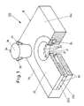
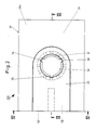
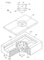
- the burner 100 shown in FIGS. 1 to 4 consists of a fuel stone 20 which has an insert trough 25a into which the insert part 25 is inserted.
- the insert part 25 is held at a distance from the bottom of the insert trough 25a by one or more spacers 25b, so that the secondary air duct 52 is formed in the insert trough.
- Openings are formed in the burner block 20 and in the insert part 25 such that a continuous opening 21 results in the burner block 20 when the insert part 25 is inserted.
- a meandering profile is formed in the area of the opening 21 in the insert part 25 on its lower side, so that the insert part 25 rests on the burner block 20 via the cams 23a, the openings 23 being formed between the cams 23a, which form the connection between the Opening 21 and the channel 24 surrounding the opening 21 form a ring, so that an air path via the secondary air supply channel 52, the annular channel 24 and the openings 23 results in the opening 21 for the secondary air, which results from the openings 23 in the area of the surface 22 the opening 21 flows out.
- a truncated cone 30 is inserted into the opening 21, which has a circular cross section with radii R 1 decreasing from the fuel storage space 41 to the combustion chamber 42, such that there is between the truncated cone surface 32 and the inner surface 22 of the opening 21 forms an annular gap 31 for the inflow of the combustion gas.
- the radii R2 of the truncated cone 30 decrease in the direction of the combustion chamber 42 to a greater extent than the radii R1 of the circular cross section of the opening 21.
- the truncated cone 30 can be placed on the surface 26 of the base body 20a by three overlapping the annular gap 31 and in the edge region of the opening 21 Holding cams 33, 34, 35 held.
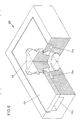
- the embodiment of the burner 200 shown in FIGS. 5, 6 and 7 is similar in its basic structure to the embodiment described above, so that only the essential differences are indicated and described below.
- the burner 200 also consists of a burner block 120 which has an insert which is essentially rectangular.
- a support edge 126 is formed in the peripheral edge of the insert trough 125a, which serves to support the insert part 125 at a distance from the bottom surface of the insert trough 125a.
- the insert 125 is held at a distance from the bottom of the insert 125a by one or more spacers 125b, so that a space remains between the insert 125 and the bottom of the insert 125a, which forms the secondary air duct 52.
- Openings are also formed in the burner block 120 and the insert 125 such that a continuous opening 121 results in the insert 120 when the insert 125 is inserted.
- an annular body surrounding the opening 121 is formed on the bottom of the insert trough 125a and has upwardly projecting cams 123a between which the openings 123 are formed, which form the connection between the opening 121 and the secondary air duct 152 surrounding the opening 121. This results in a Air path via the secondary air supply duct 152 and the openings 123 into the opening 121 for the secondary air, which flows out of the openings 123 in the area of the surface 122 of the opening 121.
- the truncated cone 130 which is held in the middle of the opening 121 by means of the holding cams 133, 134, 135, 136 arranged on the truncated cone surface 132, overlapping the annular gap 131 and placed in the edge region of the opening 121 on the surface 126 of the insert 125, has one effective length L1, that is the length with which the truncated cone 130 projects into the opening 121, which is smaller than the length L2 of the opening 121.
- the effective cross section of the annular gap 130 is increased, since the circular cross section of the opening 121 has radii R1 which decrease from the fuel storage space 41 to the combustion chamber 42, the radii R2 of the truncated cone 130 relative to the radii R1 of the circular cross section of the opening 121 from the fuel storage space Reduce 41 to the combustion chamber 42 more.
- This effect is further enhanced by the fact that the radii R ⁇ 1 in the base body 120a of the burner 120 compared to the radii R1 in the area of Increase the size of insert 125 in a transition area.
- the swirling foot surface 130a of the truncated cone 130 (FIG. 7) also creates an additional swirl within the swirl combustion chamber 60, so that an optimal oxidation of all oxidizable components in the inflowing combustion gas can be carried out.
- FIG. 8 schematically shows a boiler 40 in which a fuel block 200 is arranged, which divides the fuel storage space 41 formed in the upper part of the boiler from the combustion chamber 42.
- the solid fuel not shown in the drawing, is stored on the top 126 of the burner 200, it being ensured via the cams 27 that the opening 121 remains essentially fuel-free.
- an ember region then forms over the truncated cone 130, in which the combustion gases are generated, which are drawn into the opening 121 by the corresponding exhaust, not shown in the drawing, or are pressed in via the supplied primary air.
- the fuel storage space is supplied with primary air via the primary air duct 51, which, like the secondary air supply duct 152, is supplied with air by a blower 50.
- the optimum combustion described above then results in the vortex combustion chamber 60.
Landscapes
- Engineering & Computer Science (AREA)
- Physics & Mathematics (AREA)
- Chemical & Material Sciences (AREA)
- Combustion & Propulsion (AREA)
- Thermal Sciences (AREA)
- Mechanical Engineering (AREA)
- General Engineering & Computer Science (AREA)
- Combustion Of Fluid Fuel (AREA)
- Solid-Fuel Combustion (AREA)
- Air Supply (AREA)
- Solid Fuels And Fuel-Associated Substances (AREA)
Priority Applications (1)
| Application Number | Priority Date | Filing Date | Title |
|---|---|---|---|
| AT87116709T ATE57429T1 (de) | 1986-11-18 | 1987-11-12 | Brenner fuer einen feststoffbefeuerten kessel. |
Applications Claiming Priority (2)
| Application Number | Priority Date | Filing Date | Title |
|---|---|---|---|
| DE8630875U DE8630875U1 (de) | 1986-11-18 | 1986-11-18 | Brenner für einen feststoffbefeuerten Kessel |
| DE8630875U | 1986-11-18 |
Publications (3)
| Publication Number | Publication Date |
|---|---|
| EP0268208A2 true EP0268208A2 (fr) | 1988-05-25 |
| EP0268208A3 EP0268208A3 (en) | 1988-11-30 |
| EP0268208B1 EP0268208B1 (fr) | 1990-10-10 |
Family
ID=6800310
Family Applications (1)
| Application Number | Title | Priority Date | Filing Date |
|---|---|---|---|
| EP87116709A Expired - Lifetime EP0268208B1 (fr) | 1986-11-18 | 1987-11-12 | Brûleur pour chaudière à combustible solide |
Country Status (3)
| Country | Link |
|---|---|
| EP (1) | EP0268208B1 (fr) |
| AT (1) | ATE57429T1 (fr) |
| DE (2) | DE8630875U1 (fr) |
Cited By (7)
| Publication number | Priority date | Publication date | Assignee | Title |
|---|---|---|---|---|
| DE9110196U1 (de) * | 1991-08-17 | 1991-10-10 | Horst, Günter, 4901 Hiddenhausen | Kamineinsatz |
| FR2682176A1 (fr) * | 1991-10-07 | 1993-04-09 | Chablais Ste Financiere Cale | Chaudiere a bois a pyrolyse, a combustion inversee et tirage force. |
| EP0964202A2 (fr) | 1998-06-13 | 1999-12-15 | Ebert, Jens Dipl.-Ing. | Chaudière à bois |
| EP1158241A3 (fr) * | 2000-05-25 | 2001-12-19 | Josef Zauner | Brûleur à tirage inversé avec amenée d'air secondaire |
| WO2007131718A3 (fr) * | 2006-05-15 | 2008-03-13 | Paul Kuenzel Gmbh & Co Fa | Four pour combustibles solides |
| AT506229B1 (de) * | 2008-03-26 | 2009-07-15 | Franz Simbuerger | Holzgasofen |
| EP3492814A1 (fr) | 2017-12-04 | 2019-06-05 | Aico S.p.A. | Poêle à biomasse à émissions réduites |
Families Citing this family (5)
| Publication number | Priority date | Publication date | Assignee | Title |
|---|---|---|---|---|
| DE3935846A1 (de) * | 1989-10-27 | 1991-05-02 | Rolf Specht Stahl Und Apparate | Ofen fuer festbrennstoffe |
| DE4007849C3 (de) * | 1990-03-12 | 1999-10-07 | Hermann Hofmann | Ofen für Festbrennstoffe |
| DE102006053203A1 (de) * | 2006-11-09 | 2008-05-15 | Viessmann Werke Gmbh & Co Kg | Heizkessel für Festbrennstoffe |
| CN105910113A (zh) * | 2016-06-16 | 2016-08-31 | 中央军委后勤保障部建筑工程研究所 | 布火盘 |
| DE102017206493A1 (de) * | 2017-04-18 | 2018-10-18 | Robert Bosch Gmbh | Düsenblock zur Eindüsung von Sekundärluft in eine Brennkammer eines Festbrennstoff-Heizkessels sowie Brennkammer und Brennersystem |
Family Cites Families (4)
| Publication number | Priority date | Publication date | Assignee | Title |
|---|---|---|---|---|
| CH234066A (de) * | 1943-07-01 | 1944-09-15 | Eich Ernst | Gasfeuerungsanlage. |
| FR1016208A (fr) * | 1950-04-12 | 1952-11-05 | Morvan Ets | Appareils de chauffage |
| FR2558241B1 (fr) * | 1984-01-18 | 1989-03-31 | Tabel Rene | Chaudiere a bois comportant une chambre de prechauffage du comburant |
| US4598649A (en) * | 1985-09-03 | 1986-07-08 | Eshland Enterprises, Inc. | Particle fuel diversion structure with dome-shaped cavity |
-
1986
- 1986-11-18 DE DE8630875U patent/DE8630875U1/de not_active Expired
-
1987
- 1987-11-12 AT AT87116709T patent/ATE57429T1/de not_active IP Right Cessation
- 1987-11-12 DE DE8787116709T patent/DE3765519D1/de not_active Expired - Lifetime
- 1987-11-12 EP EP87116709A patent/EP0268208B1/fr not_active Expired - Lifetime
Cited By (7)
| Publication number | Priority date | Publication date | Assignee | Title |
|---|---|---|---|---|
| DE9110196U1 (de) * | 1991-08-17 | 1991-10-10 | Horst, Günter, 4901 Hiddenhausen | Kamineinsatz |
| FR2682176A1 (fr) * | 1991-10-07 | 1993-04-09 | Chablais Ste Financiere Cale | Chaudiere a bois a pyrolyse, a combustion inversee et tirage force. |
| EP0964202A2 (fr) | 1998-06-13 | 1999-12-15 | Ebert, Jens Dipl.-Ing. | Chaudière à bois |
| EP1158241A3 (fr) * | 2000-05-25 | 2001-12-19 | Josef Zauner | Brûleur à tirage inversé avec amenée d'air secondaire |
| WO2007131718A3 (fr) * | 2006-05-15 | 2008-03-13 | Paul Kuenzel Gmbh & Co Fa | Four pour combustibles solides |
| AT506229B1 (de) * | 2008-03-26 | 2009-07-15 | Franz Simbuerger | Holzgasofen |
| EP3492814A1 (fr) | 2017-12-04 | 2019-06-05 | Aico S.p.A. | Poêle à biomasse à émissions réduites |
Also Published As
| Publication number | Publication date |
|---|---|
| EP0268208A3 (en) | 1988-11-30 |
| ATE57429T1 (de) | 1990-10-15 |
| EP0268208B1 (fr) | 1990-10-10 |
| DE3765519D1 (de) | 1990-11-15 |
| DE8630875U1 (de) | 1987-01-29 |
Similar Documents
| Publication | Publication Date | Title |
|---|---|---|
| DE2731562C2 (de) | Brenner für flüssige und/oder gasförmige Brennstoffe | |
| DE69130479T2 (de) | Verfahren und vorrichtung zur gasverbrennung | |
| DE60106005T2 (de) | Gasbrenner für herd | |
| DE69604153T2 (de) | Gasbrenner für Küchengeräte | |
| EP0268208B1 (fr) | Brûleur pour chaudière à combustible solide | |
| DE2541991A1 (de) | Keramischer brenner | |
| DE2842125A1 (de) | Bodenfackel-vorrichtung | |
| DE1429133B1 (de) | Gasbrennerduese | |
| DE2119831C2 (de) | Gasbrenner | |
| DE602004007569T2 (de) | Luftsystem für einen Wirbelbettkessel | |
| DE1961932A1 (de) | Gasbrenner | |
| EP0871839B1 (fr) | Four a combustion avec canalisation d'air secondaire, en particulier chaudiere a combustion par le bas | |
| DE2120126A1 (de) | Hochleistungsbrenner | |
| DE3908606A1 (de) | Gasfeuerungsvorrichtung | |
| DE3733349C2 (fr) | ||
| DE4427104A1 (de) | Gasbrenner mit geringem Anteil von NOX-Gasen bei der Verbrennung von Brenngasen oder Brenngasgemischen | |
| CH691508A5 (de) | Zuluftverteilungseinrichtung für die Verbrennungsluft von Heizeinrichtungen, insbesondere für Festbrennstoffe sowie Verfahren zum Zuführen von Verbrennungsluft. | |
| DE9102176U1 (de) | Rampen-Brenner mit sogenannter überstöchiometrischer Verbrennung | |
| DE202021106558U1 (de) | Gasbrenner für eine Kochstelle | |
| DE9112869U1 (de) | Brennerstab | |
| DE29808706U1 (de) | Vorrichtung zum Beheizen von Räumen | |
| DE1964428A1 (de) | Diffusionsbrenner,insbesondere fuer Erdgas | |
| DE1905528A1 (de) | Gasbrenner,insbesondere fuer Durchlaufwassererhitzer sowie Verfahren zum Herstellen eines Gasbrenners | |
| DE29915225U1 (de) | Rohr-Lochbrenner für gasbeheiztes Grillgerät | |
| DE9314905U1 (de) | Brennerdeckel für atmosphärische Gasbrenner |
Legal Events
| Date | Code | Title | Description |
|---|---|---|---|
| PUAI | Public reference made under article 153(3) epc to a published international application that has entered the european phase |
Free format text: ORIGINAL CODE: 0009012 |
|
| AK | Designated contracting states |
Kind code of ref document: A2 Designated state(s): AT CH DE FR GB LI SE |
|
| PUAL | Search report despatched |
Free format text: ORIGINAL CODE: 0009013 |
|
| AK | Designated contracting states |
Kind code of ref document: A3 Designated state(s): AT CH DE FR GB LI SE |
|
| 17P | Request for examination filed |
Effective date: 19890128 |
|
| 17Q | First examination report despatched |
Effective date: 19890831 |
|
| DIN1 | Information on inventor provided before grant (deleted) | ||
| RAP1 | Party data changed (applicant data changed or rights of an application transferred) |
Owner name: KUENZEL, HAIKO PAUL |
|
| RIN1 | Information on inventor provided before grant (corrected) |
Inventor name: KUENZEL, HAIKO PAUL |
|
| GRAA | (expected) grant |
Free format text: ORIGINAL CODE: 0009210 |
|
| AK | Designated contracting states |
Kind code of ref document: B1 Designated state(s): AT CH DE FR GB LI SE |
|
| REF | Corresponds to: |
Ref document number: 57429 Country of ref document: AT Date of ref document: 19901015 Kind code of ref document: T |
|
| GBT | Gb: translation of ep patent filed (gb section 77(6)(a)/1977) | ||
| ET | Fr: translation filed | ||
| REF | Corresponds to: |
Ref document number: 3765519 Country of ref document: DE Date of ref document: 19901115 |
|
| PLBE | No opposition filed within time limit |
Free format text: ORIGINAL CODE: 0009261 |
|
| STAA | Information on the status of an ep patent application or granted ep patent |
Free format text: STATUS: NO OPPOSITION FILED WITHIN TIME LIMIT |
|
| 26N | No opposition filed | ||
| EAL | Se: european patent in force in sweden |
Ref document number: 87116709.4 |
|
| PGFP | Annual fee paid to national office [announced via postgrant information from national office to epo] |
Ref country code: GB Payment date: 19950914 Year of fee payment: 9 |
|
| PG25 | Lapsed in a contracting state [announced via postgrant information from national office to epo] |
Ref country code: GB Effective date: 19961112 |
|
| GBPC | Gb: european patent ceased through non-payment of renewal fee |
Effective date: 19961112 |
|
| PGFP | Annual fee paid to national office [announced via postgrant information from national office to epo] |
Ref country code: CH Payment date: 19981023 Year of fee payment: 12 |
|
| PGFP | Annual fee paid to national office [announced via postgrant information from national office to epo] |
Ref country code: FR Payment date: 19981130 Year of fee payment: 12 |
|
| PG25 | Lapsed in a contracting state [announced via postgrant information from national office to epo] |
Ref country code: LI Free format text: LAPSE BECAUSE OF NON-PAYMENT OF DUE FEES Effective date: 19991130 Ref country code: CH Free format text: LAPSE BECAUSE OF NON-PAYMENT OF DUE FEES Effective date: 19991130 |
|
| REG | Reference to a national code |
Ref country code: CH Ref legal event code: PL |
|
| PG25 | Lapsed in a contracting state [announced via postgrant information from national office to epo] |
Ref country code: FR Free format text: LAPSE BECAUSE OF NON-PAYMENT OF DUE FEES Effective date: 20000731 |
|
| REG | Reference to a national code |
Ref country code: FR Ref legal event code: ST |
|
| PGFP | Annual fee paid to national office [announced via postgrant information from national office to epo] |
Ref country code: AT Payment date: 20061122 Year of fee payment: 20 |
|
| PGFP | Annual fee paid to national office [announced via postgrant information from national office to epo] |
Ref country code: SE Payment date: 20061123 Year of fee payment: 20 |
|
| PGFP | Annual fee paid to national office [announced via postgrant information from national office to epo] |
Ref country code: DE Payment date: 20070124 Year of fee payment: 20 |
|
| EUG | Se: european patent has lapsed |