EP0268246A2 - Automatische Fokussierungsschaltung für automatische Fokusanpassung in Abhängigkeit von Videosignalen - Google Patents
Automatische Fokussierungsschaltung für automatische Fokusanpassung in Abhängigkeit von Videosignalen Download PDFInfo
- Publication number
- EP0268246A2 EP0268246A2 EP87116887A EP87116887A EP0268246A2 EP 0268246 A2 EP0268246 A2 EP 0268246A2 EP 87116887 A EP87116887 A EP 87116887A EP 87116887 A EP87116887 A EP 87116887A EP 0268246 A2 EP0268246 A2 EP 0268246A2
- Authority
- EP
- European Patent Office
- Prior art keywords
- value
- focusing lens
- focus evaluating
- focus
- focusing
- Prior art date
- Legal status (The legal status is an assumption and is not a legal conclusion. Google has not performed a legal analysis and makes no representation as to the accuracy of the status listed.)
- Granted
Links
- 230000004044 response Effects 0.000 title claims abstract description 22
- 230000008859 change Effects 0.000 claims abstract description 48
- 230000015654 memory Effects 0.000 claims description 99
- 230000003287 optical effect Effects 0.000 claims description 7
- 238000001514 detection method Methods 0.000 claims 1
- 238000010586 diagram Methods 0.000 description 29
- 238000006073 displacement reaction Methods 0.000 description 16
- 230000007246 mechanism Effects 0.000 description 11
- 230000007257 malfunction Effects 0.000 description 9
- 238000013459 approach Methods 0.000 description 7
- 230000003247 decreasing effect Effects 0.000 description 7
- 230000010354 integration Effects 0.000 description 5
- 230000000694 effects Effects 0.000 description 4
- 238000000034 method Methods 0.000 description 4
- 230000008901 benefit Effects 0.000 description 3
- 230000006870 function Effects 0.000 description 3
- 238000005070 sampling Methods 0.000 description 3
- 238000012790 confirmation Methods 0.000 description 2
- 238000001454 recorded image Methods 0.000 description 2
- 208000010201 Exanthema Diseases 0.000 description 1
- 230000002411 adverse Effects 0.000 description 1
- 238000009826 distribution Methods 0.000 description 1
- 201000005884 exanthem Diseases 0.000 description 1
- 230000006872 improvement Effects 0.000 description 1
- 206010037844 rash Diseases 0.000 description 1
Images








Classifications
-
- H—ELECTRICITY
- H04—ELECTRIC COMMUNICATION TECHNIQUE
- H04N—PICTORIAL COMMUNICATION, e.g. TELEVISION
- H04N23/00—Cameras or camera modules comprising electronic image sensors; Control thereof
- H04N23/60—Control of cameras or camera modules
- H04N23/67—Focus control based on electronic image sensor signals
- H04N23/673—Focus control based on electronic image sensor signals based on contrast or high frequency components of image signals, e.g. hill climbing method
-
- G—PHYSICS
- G03—PHOTOGRAPHY; CINEMATOGRAPHY; ANALOGOUS TECHNIQUES USING WAVES OTHER THAN OPTICAL WAVES; ELECTROGRAPHY; HOLOGRAPHY
- G03B—APPARATUS OR ARRANGEMENTS FOR TAKING PHOTOGRAPHS OR FOR PROJECTING OR VIEWING THEM; APPARATUS OR ARRANGEMENTS EMPLOYING ANALOGOUS TECHNIQUES USING WAVES OTHER THAN OPTICAL WAVES; ACCESSORIES THEREFOR
- G03B13/00—Viewfinders; Focusing aids for cameras; Means for focusing for cameras; Autofocus systems for cameras
- G03B13/32—Means for focusing
- G03B13/34—Power focusing
- G03B13/36—Autofocus systems
Definitions
- the present invention relates to an automatic focusing circuit and more particularly, to an improvement of an automatic focusing circuit for automatically matching the focus in response to a video signal obtained from an image sensor, in an image sensing apparatus such as a video camera and an electronic still camera having an automatic focusing mechanism.
- an automatic focusing apparatus used in an image sensing apparatus such as a video camera and an electronic still camera
- an approach utilizing a video signal itself obtained from an image sensor for evaluating the state where the focus is controlled has been developed. According to such an approach, a lot of good characteristics can be obtained. For example, there exists essentially no parallax. In addition, even if the depth of field is small and an object is located in the distance, the focus can be exactly matched. Furthermore, according to this approach, a specific sensor for automatic focusing need not be separately provided, so that the apparatus is very simple as a mechanism.
- a control method referred to as a so-called hill-climbing servo system has been conventionally known.
- the hill-climbing servo system is described in, for example, U. S. Patent No. 4,638,364, U. S. Patent No. 4,614,975, Japanese Patent Laying-Open Gazette No. 58505/1983 and No. 103776/1985.
- a high frequency component of a video signal obtained from an image sensor is detected every one field as a focus evaluating value, the detected focus evaluating value is always compared with a focus evaluating value detected one field before, and the position of a focusing lens continues to be slightly vibrated so that the focus evaluating value always takes the maximal value.
- Fig. 1 is a schematic block diagram showing an example of an automatic focusing circuit for a conventional video camera utilizing such a hill-climbing servo system
- Fig. 2 is a block diagram showing the details of a focus evaluating value generator 5 shown in Fig. 1.
- a video camera comprises a focusing ring 2 for moving a focusing lens 1, a focusing motor 3 for driving the focusing ring 2, and an image sensing circuit 4 including an image sensor (not shown) such as a CCD (Charge Coupled Device).
- the focusing lens 1 may be moved by a piezoelectric element instead of a motor.
- the image sensor itself such as the CCD instead of the focusing lens may be moved.
- An image formed on a surface of the image sensor by the focusing lens 1 is converted into a video signal by the image sensing circuit 4 and inputted to the focus evaluating value generating circuit 5.
- a luminance signal component in a video signal outputted from the image sensing circuit 4 is applied to a synchronizing separator circuit 5a and a gate circuit 5c.
- the synchronizing separator circuit 5a separates a vertical synchronizing signal VD and a horizontal synchronizing signal HD from the inputted luminance signal and applies the same to a gate control circuit 5b.
- the gate control circuit 5b sets a rectangular sampling area in a central portion of a picture in response to the inputted vertical synchronizing signal VD and horizontal synchronizing signal HD and a fixed output of an oscillator (not shown).
- the gate control circuit 5b applies a signal for opening or closing a gate every field to the gate circuit 5c so that passage of the luminance signal is permitted only in the range of the sampling area.
- the gate circuit 5c may be provided anywhere in the former stage of an integration circuit 5f as described below.
- Only the luminance signal corresponding to the range of the sampling area is applied to a high-pass filter 5d every field by the gate circuit 5c.
- the high frequency component of the video signal separated by the high-pass filter 5d is amplitude-detected by a detector 5e, the detected output being applied to the integration circuit 5f.
- the integration circuit 5f integrates every filed the detected output applied thereto, the integrated output being applied to an A/D converter 5g.
- the A/D converter 5g converts the integrated value inputted thereto into a digital value and supplies the digital value as a focus evaluating value in the current field.
- the supplied focus evaluating value is applied to a first memory 6 as described below.
- a focus evaluating value outputted from the focus evaluating value generating circuit 5 is stored in the first memory 6.
- data stored in the first memory 6 is transferred to a second memory 7. More specifically, the contents of the first memory 6 and the second memory 7 are updated every field, so that the newest focus evaluating value and a focus evaluating value one field before are always stored in the first memory 6 and the second memory 7, respectively.
- the contents of the two memories 6 and 7 are inputted to a comparator 8 and compared therein. The compared output is applied to a focusing motor control circuit 9.
- the focus evaluating value stored in the first memory 6 is larger than that stored in the second memory 7, the focus evaluating value is increasing, so that the focusing motor control circuit 9 maintains the current rotational direction of the focusing motor 3 in response to an output of the comparator 8.
- the focus evaluating value stored in the first memory 6 is smaller than that stored in the second memory 7, the focus evaluating value is decreasing, so that the focusing motor control circuit 9 reverses the rotational direction of the focusing motor 3 in response to the output of the comparator 8.
- the focusing ring 2 supporting the focusing lens 1 continues to move in the direction of increasing a focus evaluating value by such movement of the focusing motor 3, so that an in-focus state is achieved. After achieving the in-focus state, the focusing ring 2 and the focusing lens 1 continue to be vibrated back and forth in the vicinity of the maximal point of the focus evaluating value.
- the lens 1 is not stopped in the defocused position by driving the focusing lens 1 in the direction of always increasing the focus evaluating value even if an object is changed, so that very good follow-up characteristics can be achieved.
- a first disadvantage is that since the focusing lens is not stopped even in the in-focus state, a picture continues to be vibrated even if an object at rest is in focus. For example, the focal length of a lens currently used in a television camera is changed by rotating the focusing ring, so that the angle of field of a sensed image is changed. Therefore, in the above described system in which the focusing ring continues to be vibrated even in the in-focus state, the object on the picture becomes large or small with a particular period, resulting in a very unclear picture.
- a second disadvantage is directed to a power consumption.
- a home video camera currently utilizes a battery as a power supply due to the portability thereof.
- a focusing motor is always driven as in the above described hill-climbing servo system so that the forward rotation and the reverse rotation are repeated, more power is consumed, as compared with when the focusing motor is rotated in a constant direction, due to rash current, so that the time period during which an image can be recorded by using such a battery becomes short.
- the focus evaluating value is increased or decreased as the whole in such a manner that increase or decrease of the focus evaluating value concerning the matching of the focus caused by displacement of the focusing lens itself is overlapped with increase or decrease of the focus evaluating value caused by unintentional movement of the hand and movement of an object.
- a second disadvantage is that a threshold value for resuming hill-climbing operation must be decreased to improve the follow-up characteristics of the position of the focus.
- the threshold value is decreased, the hill-climbing operation is resumed due to slight movement of an object even in the in-focus state, so that the lens moves, resulting in an unclear picture. Therefore, if the threshold value is set large, the possibility that the lens continues to be erroneously stopped in the defocused position is increased.
- the S/N ratio in the high frequency of a video signal is deteriorated as compared with that in the low frequency thereof, so that it is likely that it is determined that the focus is matched due to the presence of a noise component in the high frequency.
- the threshold value for determining the presence or absence of a particular high frequency component is increased, there are many cases where the lens is not stopped even if the object is in focus.
- some video cameras and electronic still camera have both the automatic focusing mechanism and a zoom mechanism.
- the depth of field depends on the zoom region, that is, the place where a zoom lens which is a variable-power lens is located between the telephoto position and the wide-angle position. More specifically, if the zoom is located in the wide-angle region, the depth of field becomes large. This means that the in-focus state is easily maintained even if an object slightly moves back and forth from the in-focus position. On the other hand, if the zoom is located in the telephoto region, the depth of field becomes small. This means that it is difficult to maintain the in-focus state.
- the amount of change of the focus evaluating value is smaller if the zoom is located in the wide-angle region and larger if the zoom is located in the telephoto region, with respect to a predetermined amount of displacement of the focusing lens.
- a threshold value for determining the maximal point and a threshold value for resuming hill-climbing operation are fixed values, more time is required for detecting the threshold values when the zoom is located in the wide-angle region, as compared with the situation where the zoom is located in the telephoto region, so that it is difficult to perform fast automatic focusing operation.
- a primary object of the present invention is to provide an automatic focusing circuit in which a focusing lens is not vibrated when the focus is matched and a picture is clear.
- Another object of the present invention is to provide an automatic focusing circuit which can prevent malfunction that the focusing lens is stopped in the defocused state.
- Still another object of the present invention is to provide an automatic focusing circuit which can prevent resumption of unnecessary automatic focusing operation.
- a further object of the present invention is to provide an automatic focusing circuit capable of performing fast and stable automatic focusing operation irrespective of the zoom region.
- the present invention is directed to an automatic focusing circuit for automatically matching the focus in response to a video signal obtained from image sensing means, the automatic focusing circuit comprising focus evaluating value detecting means for detecting a level of a high frequency component of a video signal every constant period, converting the level into a focus evaluating value which takes the maximum value in the in-focus position or a focus evaluating value which takes the minimum value in the in-focus position and sequentially supplying the converted value.
- First automatic focusing operation is performed by first control means so that the position of the focusing lens is once fixed in the position where the focus evaluating value takes the maximum value or the minimum value.
- second automatic focusing operation is performed by second control means so that the position of the focusing lens is changed, by a very small amount, a change of the focus evaluating value relative to the change is detected and the position of the focusing lens is corrected to the maximal point or the minimal point of the focus evaluating value.
- the correction amount of the position of the focusing lens by the second control means exceeds a predetermined value, the automatic focusing operation by the first control means is resumed.
- the characteristic of the automatic focusing control is switched depending on the zoom position detected by the zoom position detecting means.
- a principal advantage of the present invention is that since coarse adjustment and fine adjustment of automatic focusing operation are independently made by two control circuits, the conformity and the stability required for automatic focusing control can be achieved. More specifically, the focusing lens need not continue to be moved in the in-focus position, and the focusing lens can be prevented from erroneously being stopped by the change of the distance between an object and the lens. In addition, since a threshold value for resuming coarse adjustment can be set large, unnecessary automatic focusing operation which affects a picture can be controlled to a minimum.
- Another advantage of the present invention is that when the characteristic of automatic focusing control is switched depending on the zoom position of the zoom lens, stable automatic focusing operation can be performed irrespective of the zoom position.
- Fig. 3 is a schematic block diagram of an automatic focusing circuit according to a first embodiment of the present invention.
- a video camera comprises a focusing ring 2 for moving a focusing lens 1, a focusing motor 3 for driving the focusing ring 2, and an image sensing circuit 4 including an image sensor (not shown) such as a CCD.
- the focusing lens 1 may be moved by a piezoelectric element instead of a motor.
- the image sensor itself such as the CCD instead of the focusing lens may be moved.
- An image formed on the image sensor by the focusing lens 1 is converted into a video signal by the image sensing circuit 4 and inputted to a focus evaluating value generating circuit 5.
- the focus evaluating value generating circuit 5 has the same structure as that in the above described Fig. 2 and therefore, the description thereof is omitted.
- a switching circuit 16 is controlled to be switched in response to an output from a switching control circuit 23 as described below. More specifically, when the switching circuit 16 is switched on the side of a terminal 16a, an output from a first focusing motor control circuit 15 as described below is selected and applied to the focusing motor 3, so that rotation of the focusing motor 3 is controlled. On the other hand, when the switching circuit 16 is switched on the side of a terminal 16b, an output from a second focusing motor control circuit 17 as described below is selected and applied to the focusing motor 3, so that the rotation of the focusing motor 3 is controlled.
- the first focusing motor control circuit 15 rotates the focusing motor 3 in the above described predetermined direction until the comparator 13 generates a comparison output indicating "large” or "small". If and when a comparison output indicating that the current focus evaluating value is larger than the initial focus evaluating value held in the initial value memory 11 is outputted from the comparator 13, the first focusing motor control circuit 15 maintains the above described predetermined rotational direction. On the other hand, when a comparison output indicating that the current focus evaluating value is smaller than the initial focus evaluating value is obtained, the first focusing motor control circuit 15 reverses the rotational direction of the focusing motor 3. Initialization of the rotational direction of the focusing motor 3 is completed in the above described manner.
- the first focusing motor control circuit 15 monitors an output of a comparator 12.
- the comparator 13 may be adapted not to generate a comparison output indicating "large” or "small” while the difference between the initial focus evaluating value and the current focus evaluating value does not exceed a predetermined threshold value.
- the comparator 12 compares the maximum focus evaluating value so far held in the maximum value memory 10 with the current focus evaluating value outputted from the focus evaluating value generating circuit 5, and outputs three kinds of comparison signals, that is, signals in first, second and third modes in which the current focus evaluating value is larger than, the same as or slightly lower than, and sufficiently smaller than the focus evaluating value held in the maximum value memory 10, respectively. If and when the current focus evaluating value is larger than the content of the maximum value memory 10, the content of the maximum value memory 10 is updated in response to the output of the comparator 12, so that the maximum value of the focus evaluating value so far is always held in the maximum value memory 10.
- a signal indicating the position of a focusing motor is generated from the focusing motor 3 corresponding to the position of the focusing ring 2 supporting the focusing lens 1 and applied to a memory 14 holding the position of a focusing motor.
- the focusing motor position memory 14 is updated in response to the output of the comparator 12 and always holds a focusing motor position signal in which the focus evaluating value becomes maximum.
- the first focusing motor control circuit 15 monitors the output of the comparator 12 while rotating the focusing motor 3 in the direction initialized in response to the output of the comparator 13 as described above.
- the first focusing motor control circuit 15 reverses the rotational direction of the focusing motor 3. It is to prevent malfunction due to noise of the focus evaluating value that the focusing motor is first reversed not by the output in the second mode but by the output in the third mode.
- a comparator 30 compares the content of the focusing motor position memory 14 corresponding to the maximum value of the focus evaluating value with the current focusing motor position signal generated from the focusing motor 3. When both coincide with each other, that is, the focusing ring 2 is returned to the position where the focus evaluating value is the maximum, the first focusing motor control circuit 15 stops rotation of the focusing motor 3. At the same time, the first focusing motor control circuit 15 outputs a lens stop signal LS and applies the same to the switching control circuit 23 and the second focusing motor control circuit 17.
- the switching control circuit 23 is responsive to the lens stop signal LS for controlling the switching circuit 16 to be switched on the side of the terminal 16b. Subsequently, the rotation of the focusing motor 3 is controlled by an output of the second focusing motor control circuit 17.
- Control by the second focusing motor control circuit 17 is briefly described. After the focusing motor 3 is once stopped by the first focusing motor control circuit 15, the focusing lens 1 is displaced, by a very small amount, by driving the focusing motor 3 again, the slope of the focus evaluating value is confirmed, and the position of the focusing lens 1 is adjusted in a fine manner so that the focus evaluating value is located in the maximal value.
- the second focusing motor control circuit 17 is formed by a microcomputer.
- Fig. 4 is a flow chart of internal operation thereof.
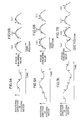
- Figs. 5A to 8B are diagrams for explaining the movements of the focusing motor 3 and the focusing lens 1 at the time of control by the second focusing motor control circuit 17.
- the axis of ordinate represents the rotational direction of the focusing motor 3, the forward direction being a direction initialized in a step S1 shown in Fig. 4 as described below.
- the axis of abscissa represents time. Additionally, in each of (a), (b) and (c) of Figs.
- the axis of ordinate (which is omitted except for (a)) represents a focus evaluating value
- the axis of abscissa (which is omitted except for (a)) represents the position of a lens (the distance between the focusing lens 1 and a CCD).
- the rotational direction of the focusing motor 3 is initialized (step S1). More specifically, the focusing motor 3 is immediately rotated in a predetermined direction, and the rotational direction is held in the second focusing motor control circuit 17.
- step S2 the current focus evaluating value outputted from the focus evaluating value generating circuit 5 is held in a memory 19 as a reference value (step S2).
- the focusing motor 3 is rotated, by a very small amount, in the rotational direction held in the above described step S1 (step S3).
- the focusing lens 1 is displaced, by a very small amount ⁇ T (where ⁇ T is one unit), in the initialized direction.
- the very small amount ⁇ T of displacement is extremely smaller than the amount of displacement of the focusing lens 1 by the first focusing motor control circuit 15 and hardly affects an image.
- a comparator 18 compares the reference value held in the memory 19 in the step S2 with the current focus evaluating value outputted from the focus evaluating value generating circuit 5 (step S4). As represented by numeral 2 in Figs. 5A and 5B(b), if the current focus evaluating value is smaller, the rotational direction of the focusing motor 3 currently held inside is reversed, and the focusing lens 1 is displaced, by two units, in the reversed direction (step S5).
- the comparator 18 compares again the reference value held in the memory 19 with the current focus evaluating value (step S6).
- the current focus evaluating value is smaller, the rotational direction of the focusing motor 3 is reversed again, and the focusing lens 1 is returned, by one unit, in the reversed direction (step S7). More specifically, control is performed such that the focusing lens 1 is displaced, by a very small amount, back and forth from the position of the lens stopped by the first focusing motor control circuit 15 to such an extent that the image is not affected, it is confirmed that the focus evaluating value in the position of the lens first stopped is the maximal, and the lens is returned to the original stop position and enters the wait state.
- the second focusing motor control circuit 17 initializes the rotational direction of the focusing motor 3 (step S1), and holds the reference value in the memory 19 (step S2). Thereafter, the focusing motor 3 is rotated, by a very small amount, in the direction indicated by the data being held so that the lens 1 is displaced by one unit (step S3), and the current focus evaluating value are compared with the reference value (step S4). Since the stop position of the lens 1 by the first focusing motor control circuit 15 deviates from the maximal value of the focus evaluating value, the current focus evaluating value after very small displacement is larger than the reference value, as represented by numeral 1 in Fig. 6B(a).
- step S8 Internal operation of the second focusing motor control circuit 17 proceeds to the step S8.
- step S8 it is determined whether or not the stop point was moved by more than N units, from the first stop point. Since this determination is concerned with whether or not the stop point considerably deviates from the maximal point, N is set to be a large value to some extent. Thus, in the step S8, determination "NO" is first made, so that the program returns to "A”. Then, the content of the memory 19 is updated, and a focus evaluating value in the position after very small displacement which is larger than the focus evaluating value in the first stop point is held as a new reference value (step S2).
- Figs. 7A and 7B illustrate the case in which the focus evaluating value becomes larger in the direction opposite to the initialized direction.
- the focus evaluating value attains the maximal point by displacing the lens by two units to the left from the first stop position, as represented by numerals 1, 2 and 3.
- the subsequent operation represented by numerals 4, 5 and 6 is the same as that represented by the numerals 1, 2 and 3 in Figs. 5A and 5B except that the polarity is inverted.
- the focusing lens 1 can also attain the maximal point of the focus evaluating value by the second focusing motor control circuit 17 as described above, the amount of each displacement is very small so that a picture is not affected. Thus, if and when the stop point of the lens by the first focusing motor control circuit 15 considerably deviates from the maximal point of the focus evaluating value, much time is required for correcting deviation, so that fast automatic focusing operation can not be expected.
- step S8 it is determined whether or not the maximal point deviates, by a predetermined amount, from the stop point. More specifically, in the step S8, it is determined whether or not correction by very small displacement is made more than N times, that is, the position of the focusing lens 1 is displaced by more than N units. Thus, if and when very small correction is made as shown in Figs. 5A to 7B and the position is not displaced by more than N units even in any direction from the first stop point of the lens, the program is jumped to "A" in Fig. 4, where the focus continues to be adjusted in a fine manner.
- the second focusing motor control circuit 17 when it is determined that the lens 1 moves by more than N units in any direction from the first stop point, the second focusing motor control circuit 17 outputs a signal for confirming that the focus is not matched and applies the same to the switching control circuit 23 through an OR circuit 22.
- the switching control circuit 23 is responsive to the defocused state confirming signal for switching again the switching circuit 16 on the side of the terminal 16a. Accordingly, the focusing motor 3 is controlled by an output of the first focusing motor control circuit 15 instead of an output of the second focusing motor control circuit 17, so that fast automatic focusing operation by large displacement of the lens is performed.
- a memory 20 and a comparator 21 are circuits for resuming coarse adjustment by the first focusing motor control circuit 15 when an object is changed during fine adjustment by the second focusing motor control circuit 17. More specifically, a focus evaluating value at the time point when automatic focusing operation by the first focusing motor control circuit 15 is completed and the lens stop signal LS is generated is held in the memory 20.
- the comparator 21 compares the content of the memory 20 with the current focus evaluating value outputted from the focus evaluating value generating circuit 5. When the difference becomes larger than a predetermined threshold value, a signal indicating that an object change is outputted assuming that an object changed. The signal is inputted to the switching control circuit 23 through the OR circuit 22. Accordingly, the switching control circuit 23 switches the switching circuit 16 on the side of the terminal 16a. As the result, automatic focusing operation by the first focusing motor control circuit 15 is resumed, so that automatic focusing operation following the change of an object is achieved.
- the focusing motor 3 when it is confirmed by the second focusing motor control circuit 17 that the stop point of the lens 1 by the first focusing motor control circuit 15 is the maximal point, the focusing motor 3 continues to be stopped until the change of the object is determined by the above described comparator 21.
- the maximal point is intermittently and repeatedly confirmed by the second focusing motor control circuit 17 at a particular interval irrespective of the result of comparison made by the comparator 21, the reliability of automatic focusing operation is further increased.
- the lens when the lens is stopped in the true in-focus position, the movement of the lens is only very small displacement by the second focusing motor control circuit 17, so that an image is not affected significantly. Additionally, when it is determined by the comparator 21 that the object changed, automatic focusing operation is resumed by the first focusing motor control circuit 15. However, since fine adjustment is separately made by the second focusing motor control circuit 17, the threshold value for the resuming automatic focusing operation by the control circuit 15 can be set large, so that unnecessary automatic focusing operation which affects a picture can be controlled to a minimum.
- Fig. 9 is a schematic block diagram of an automatic focusing circuit according to a second embodiment of the present invention.
- the automatic focusing circuit shown in Fig. 9 is the same as that in the first embodiment shown in Fig. 3 except for the following.
- a video camera show in Fig. 9 has both an automatic focusing mechanism and a zoom mechanism, and comprises a zoom ring 52 for supporting a zoom lens (not shown), a zoom motor 61, a position detecting switch 54 for detecting the zoom region, and a threshold value setting memory 60 connected to the position detecting switch 54.
- Fig. 10 is a diagram showing a structure of a zoom ring portion shown in Fig. 9, and Fig. 11 is a diagram showing the details of the position detecting switch 54.
- a zoom ring 52 supporting a zoom lens (not shown) which is a variable-power lens is rotatably provided in the radial direction in a lens cylinder 51 projected forward from a main body 50 of a video camera. Since the zoom ring 52 is driven by the zoom motor 61 (in Fig. 9) and rotated, the variable-power lens moves in the direction of an optical axis and on the telephoto or wide-angle side.
- a cam portion 53 is integrally formed in a forward end of the periphery of the zoom ring 52, the cam portion 53 comprising a first stepped portion 53a, a second stepped portion 53b and a third stepped portion 53c, each having gradually different amounts projected forward.
- the position detecting switch 54 is fixed to the lens cylinder 51 so that an operating rod 54a abuts on the cam portion 53.
- the position detecting switch 54 is a triple changeover switch, which is switched in three steps when the operating rod 54a sequentially abuts on the first stepped portion to the third stepped portion 53a, 53b and 53c.
- An output of the position detecting switch 54 is supplied to the threshold value setting memory 60, so that signals are processed.
- a comparator 12 (in Fig.
- a first threshold value N1, a second threshold value N2 and a third threshold value N3 are stored in advance in the threshold value setting memory 60. Any of the three kinds of threshold data is selectively outputted in response to the output of the position detecting switch 54.
- the zoom ring 52 When the zoom ring 52 is located on the wide-angle side, that is, the operating rod 54a abuts on the first stepped portion 53a and located in a first position represented by a solid line A (in Fig. 11), terminals 55 and 56 are rendered conductive, so that information indicating the rotational position at "H” and "L” levels are supplied to input terminals 60a and 60b of the threshold value setting memory 60, respectively.
- the threshold value setting memory 60 is responsive to the rotational position information for outputting the first threshold value N1 and applying the same to the comparator 12.
- the operating rod 54a slides along the cam portion 53 and abuts on the second stepped portion 53b. More specifically, the operating rod 54a moves to a second position represented by a dotted line B (in Fig. 11).
- terminals 55 and 57 are rendered conductive, so that rotational position information at the "H” and "H" levels are supplied to the input terminals 60a and 60b of the threshold value setting memory 60, respectively.
- the threshold value setting memory 60 is responsive to the rotational position information for outputting the second threshold value N2 and applying the same to the comparator 12.
- the operating rod 54a When the zoom ring 52 further rotates on the telephoto side, the operating rod 54a abuts on the third stepped portion 53c. More specifically, the operating rod 54a moves to a third position represented by a dotted line C (Fig. 11). As a result, the terminals 56 and 57 are rendered conductive, so that rotational position information at "L” and "H” levels are supplied to the input terminals 60a and 60b of the threshold value setting memory 60, respectively.
- the threshold value setting memory 60 is responsive to the rotational position information for outputting the third threshold value N3 and applying the same to the comparator 12.
- a first focusing motor control circuit 15 monitors the output of the comparator 12 while rotating a focusing motor 3 in the direction initialized in response to an output of a comparator 13, as in the above described first embodiment. In order to prevent malfunction due to noise of a focus evaluating value, the first focusing motor control circuit 15 reverses the focusing motor 3 when it is determined that a drop of the current focus evaluating value from the maximum focus evaluating value exceeds the threshold value outputted from the threshold value setting memory 60.
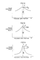
- Figs. 12 to 14 are diagrams for explaining timing for reversing the focusing motor 3.
- Fig. 12 illustrates the case in which a zoom is located in a wide-angle region
- Fig. 13 illustrates the case in which the zoom is located in an intermediate region
- Fig. 14 illustrates the case in which the zoom is located in the telephoto region.
- the axis of abscissa represents the position of a focusing lens and the axis of ordinate represents the focus evaluating value.
- the second threshold value N2 outputted from the threshold value setting memory 60 is set to be larger than the above described first threshold value N1. Therefore, as shown in Fig. 13, the focusing motor 3 is reversed at a point Q ⁇ overshot from the in-focus position P by distance ⁇ l.
- a third threshold value N3 outputted from the threshold value setting memory 60 is set to be larger than the first threshold value N1 and the second threshold value N2, the focusing motor 3 is reversed at a point Q ⁇ overshot from the in-focus position P by distance ⁇ l.
- the focusing motor 3 is reversed at a point overshot from the in-focus position by distance ⁇ l even if the zoom region is located in any of the wide-angle region, the intermediate region and the telephoto region.
- a comparator 30 compares the content of a focusing motor position memory 14 corresponding to the maximum value of the focus evaluating value with the current focusing motor position signal generated from the focusing motor 3.
- the first focusing motor control circuit 15 stops the rotation of the focusing motor 3.
- the first focusing motor control circuit 15 outputs a lens stop signal LS and applies the same to a switching control circuit 23 and a second focusing motor control circuit 17.
- the switching control circuit 23 is responsive to the lens stop signal LS for controlling a switching circuit 16 to be switched on the side of a terminal 16b.
- the focusing motor 3 is controlled by an output of the second focusing motor control circuit 17.
- the conformity of automatic focusing operation is improved by the first focusing motor control circuit 15 and the in-focus point is confirmed in a fine manner by the second focusing motor control circuit 17 in the vicinity of the in-focus position, so that the stability is improved.
- the focusing motor control circuit 17 determines that the maximal point considerably deviates from the stop point and outputs a defocused state confirming signal, so that fast automatic focusing operation by the first focusing motor control circuit 15 is started.
- setting of the above described N performs a very important function for performance of automatic focusing operation.
- Fig. 15 is a diagram showing the relation between the change of the focus evaluating value relative to the position of the zoom ring and the number of steps in peak confirming operation at the time of fine adjustment by the second focusing motor control circuit 17.
- the axis of ordinate represents the focus evaluating value
- the axis of abscissa represents the position of the lens. More specifically, the scale shows diagrammatically the amount of each displacement of the position of the lens by the second focusing motor control circuit 17.
- Fig. 15 shows diagrammatically the amount of each displacement of the position of the lens by the second focusing motor control circuit 17.
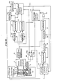
- Fig. 16 is a schematic block diagram of an automatic focusing circuit according to a third embodiment of the present invention, which object is to solve the above described problems.
- the automatic focusing circuit shown in Fig. 16 is the same as that in the second embodiment shown in Fig. 9 except for the following. More specifically, the threshold value setting memory 60 shown in Fig. 9 is not provided, and an output of a position detecting switch 54 is applied to a second focusing motor control circuit 17 instead of the threshold value setting memory 60.
- a zoom ring 52 shown in Fig. 16 is the same as that in the second embodiment shown in Fig. 10 and therefore, the detailed description thereof is omitted.
- Fig. 17 is a diagram for explaining the position detecting switch 54 and a connecting relation thereof shown in Fig. 16.
- the operating rod 54a When the zoom ring 52 further rotates on the telephoto side, the operating rod 54a abuts on a third stepped portion 53c. More specifically, the operating rod 54a moves to a third position represented by a dotted line C (in Fig. 17). As a result, terminals 56 and 57 are rendered conductive, so that rotational position information at the "L” and “H” levels are supplied to the input terminals 70a and 70b of the threshold value memory 70, respectively, whereby it can be known that the zoom is in the telephoto region.
- the second focusing motor control circuit 17 starts second automatic focusing operation in response to a signal indicating the above described zoom region.
- the second focusing motor control circuit 17 is formed by a microcomputer, similarly to the first and second embodiments.
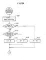
- Figs. 18A and 18B are flow charts of internal operation thereof.
- the second focusing motor control circuit 17 is responsive to a signal from the position detecting switch 54 (step S101) for determining the zoom position and determining the number of times of searching the in-focus state. It is first determined whether or not the zoom is located in the telephoto region (step S102). If it is located in the telephoto region, N is set to be equal to N3 (step S103). If it is not located in the telephoto region, it is determined whether or not it is located in the intermediate region (step S104). If the zoom is located in the intermediate region, N is set to be equal to N2 (step S105). In addition, if the zoom is not located in the intermediate region, it is automatically determined that the zoom ring 52 is located in the wide-angle region, so that N is set to be equal to N1 (step S106).
- step S107 in Fig. 18B the rotational direction is initialized (step S107 in Fig. 18B), as in the first embodiment. Thereafter, peak confirming operation is performed in the same procedure as that in the above described Fig. 4. More specifically, operation in the steps S107 to S114 in Fig. 18B is the same as that in Fig. 4 and therefore, the description thereof is omitted.
- Setting of the value N is setting of the number of repetitions of confirmation of a peak in the step S114.
- the value N is set so that N1 equals 8, N2 equals 6 and N3 equals 4.
- the value N2 is the same as that in the first embodiment.
- the value N is set small in the telephoto region and the value N is set large in the wide-angle region. More specifically, in the telephoto region where the focus evaluating value is liable to extremely change as shown in Fig. 15 (1), it is determined that the maximal point considerably deviates from the stop point if the in-focus state is not achieved by performing confirming operation of the peak four times, so that first automatic focusing operation is resumed. On the other hand, in the wide-angle region where the focus evaluating value does not change very much as shown in Fig. 15 (2), the first automatic focusing operation is not resumed until the confirming operation of the peak is performed eight times.
- the third embodiment in the telephoto region where an image changes remarkably and the conformity is required, only a few searching operation are required and then, the first automatic focusing operation is started.
- a number of searching operations are required, the number of which is twice the number of times in the telephoto region and then, the first automatic focusing operation is started.
- the above described number N of repetitions of confirmation of a peak should be set in consideration of resolution of an image sensing optical system including an image sensor, the depth of focus of a lens and the S/N ratio of a video circuit.
- the zoom region is divided into three regions, that is, a telephoto region, an intermediate region and a wide-angle region, the zoom region may be divided into more than three regions depending on an optical system and a circuit system.
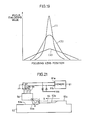
- the shape of the change of the focus evaluating value relative to the position of the lens extremely differs depending on whether the zoom is located in the telephoto region or the wide-angle region, as shown in Fig. 19. More specifically, when the zoom is located in the telephoto region, the focus evaluating value changes steeply as shown in Fig. 19 (1). On the other hand, if the zoom is located in the wide-angle region, the focus evaluating value changes very slowly as shown in Fig. 19 (2).
- the first focusing motor control circuit 15 when the first focusing motor control circuit 15 outputs the lens stop signal LS so that the first automatic focusing operation is interrupted and then, the first focusing motor control circuit 15 resumes the first automatic focusing operation in response to an output of the comparator 21, it is desirable that the first automatic focusing operation is performed after the focus evaluating value extremely changes if hill-climbing servo operation is performed in the telephoto region. More specifically, it is desirable that a threshold value of the comparator 21 is set large.
- the depth of focus is so large that matching of focus is not required. Therefore, even if the lens slightly moves from an object, the sharpness of a picture does not change very much except an object close to the lens. If the focusing ring is moved under these conditions, the focus of the object does not change but only the angle of field changes, so that the very adverse effect is psychologically exerted. Thus, even in the wide-angle region, it is desirable that only when the focus evaluating value changes clearly, that is, the state of the object changes clearly, hill-climbing servo operation by the first focusing motor control circuit 15 is resumed. Thus, even in the wide-angle region, the threshold value of the comparator 21 must be set large for the first automatic focusing operation, for a different reason from that in the above described telephoto region.
- the focus evaluating value changes in the intermediate state between the above described states (1) and (2), as shown in Fig. 19 (3). More specifically, since the depth of focus is not very large and the focus evaluating value considerably changes relative to the movement of the object, automatic focusing operation must be performed in a fine manner to follow the movement of the object. Thus, the threshold value of the comparator 21 for resuming the first automatic focusing operation must be set to be smaller than those in the telephoto and wide-angle regions.
- the first focusing motor control circuit 15 is not restarted in the intermediate region unless the recorded image is considerably defocused.
- the above described threshold value is set to a constant value assuming the intermediate region, the recorded image is defocused although the object does not change in the telephoto region, and the angle of field changes although the sharpness of the picture does not change in the wide-angle region.
- Fig. 20 is a schematic block diagram of an automatic focusing circuit according to a fourth embodiment of the present invention, which object is to solve the above described problems.
- the automatic focusing circuit shown in Fig. 20 is the same as that in the third embodiment shown in Fig. 16 except for the following. More specifically, the automatic focusing circuit comprises a difference output generating circuit 80 for outputting the absolute value of the difference between a focus evaluating value held in a memory 20 and the current focus evaluating value outputted from a focus evaluating value generating circuit 5, a threshold value memory 81 receiving outputs of the memory 20 and a position detecting switch 54, and a comparator 82 for comparing outputs of the difference output generating circuit 80 and the threshold value memory 81.
- a zoom ring 52 shown in Fig. 20 is the same as that in the second embodiment shown in Fig. 10.
- Fig. 21 is a diagram for explaining a connecting relation of the position detecting switch 54.
- the operating rod 54a When the zoom ring 52 further rotates on the telephoto side, the operating rod 54a abuts on a third stepped portion 53c. More specifically, the operating rod 54a moves to a third position represented by a dotted line C (in Fig. 21). As a result, the terminals 56 and 57 are rendered conductive, so that rotational position information at the "L” and "H” levels are supplied to the input terminals 81a and 81b of the threshold value memory 81, respectively, whereby it can be known that the zoom lens is located in the telephoto region.
- the threshold value memory 81 is responsive to a signal from the position detecting switch 54 for changing the output thereof.
- the comparator 82 compares the output of the difference output generating circuit 80 with the output of the threshold memory 81 which changes depending on the zoom position as described above. As a result, if the output of the difference output generating circuit 80 is larger than that of the threshold value memory 81, a signal indicating that an object changed is applied to a switching control circuit 23. Accordingly, the switching control circuit 23 switches a switching circuit 16 on the side of a terminal 16a. As a result, automatic focusing operation by a first focusing motor control circuit 15 is resumed.
- the maximal value of the focus evaluating value held in the memory 20 by a signal from the first focusing motor control circuit 15 is A.
- the difference output generator 80 calculates the absolute value
- the threshold value memory 81 outputs A/2 when a zoom position signal from the position detecting switch 54 indicates the telephoto and wide-angle regions and outputs A/4 when it indicates the intermediate region.
- the comparator 82 compares an output of the above described absolute value
- the threshold value for restarting the first focusing motor control circuit 15 when an object is changed during automatic focusing operation by the second focusing motor control circuit 17 is automatically changed corresponding to the telephoto, intermediate and wide-angle regions, automatic focusing operation can be performed in a fine manner.
- Fig. 22 is a schematic block diagram showing an automatic focusing circuit according to a fifth embodiment of the present invention.
- the automatic focusing circuit shown in Fig. 22 is the same as that in the first embodiment shown in Fig. 3 except for the following. More specifically, a comparator 90 for receiving and comparing the content of a maximum value memory 10 with the current focus evaluating value outputted from a focus evaluating value generating circuit 5 is provided separately from a comparator 12.
- a focusing motor 3 is immediately reversed. After the focusing motor 3 is reversed, updating of the value held in the maximum value memory 10 is stopped by an output of a first focusing motor control circuit 15, and a comparator 30 compares the content of a focusing motor position memory 14 with the current focusing motor position signal. When both coincide with each other, that is, a focusing ring 2 is returned to the position where the focus evaluating value becomes the maximum, the first focusing motor control circuit 15 functions such that the focusing motor 3 is stopped.
- the first focusing motor control circuit 15 refers to an output of the comparator 90. If the difference between the content of the maximum value memory 10 whose updating is stopped after the focusing motor 3 is reversed and the current focus evaluating value is larger than a predetermined threshold value, a comparison signal at an "H" level is generated.
- the focus evaluating value depends on only the position of the focusing ring 2. Therefore, at the time point when the focusing ring 2 is returned to the position where the focus evaluating value becomes the maximum the current focus evaluating value outputted from a focus evaluating value generating circuit 5 and the content of the maximum value memory 10 become almost equal, so that the comparator 90 should output a comparison signal at an "L" level.
- the current focus evaluating value is not equal to the content of the maximum value memory 10 even if the focusing ring 2 is returned to the original position, so that the comparison output of the comparator 90 attains the "H" level.
- the comparison output of the comparator 90 is at the "H" level as described above after the focusing ring 2 is reversed and stopped, the maximum value memory 10 and an initial value memory 11 are cleared so that automatic focusing operation by the first focusing motor control circuit 15 is performed from the beginning.
- the comparison output of the comparator 90 is at the "L" level after the focusing ring 2 is reversed, the first focusing motor control circuit 15 outputs a lens stop signal LS, so that the second automatic focusing operation by a second focusing motor control circuit 17 is started as in the above described first embodiment.
- the current focus evaluating value and the maximal value being held are compared with each other so that the maximal point is reconfirmed, stable automatic focusing operation without malfunction due to unintentional movement of the hands of a camera and vigorous movement of an object can be achieved.
- the focusing ring 2 is returned to the maximal point of the focus evaluating value by the comparator 30 and the first focusing motor control circuit 15 during first automatic focusing operation.
- the focus evaluating value in a particular position A of the lens is outputted from the focus evaluating value generating circuit 5 after an optical image is sensed in an image sensor during one field period in the lens position A and then, is read out as a video signal during the next one field period. More specifically, the focus evaluating value in the particular lens position A is outputted two field period late.
- the focusing ring 2 when the maximal value of the focus evaluating value is outputted from the focus evaluating value generating circuit 5 if the focusing motor 3 is moving, it is considered that the focusing ring 2 has actually overshot the maximal point. Thus, even if the focusing motor 3 is returned to the position of the motor when the maximal value of the focus evaluating value is outputted, the focusing ring 2 may not sufficiently returned.
- the second reason is that even if the focusing motor 3 is reversed, motion is not transmitted to the focusing ring 2 by a certain amount immediately after reverse rotation, due to backlash of a driving system from the focusing motor 3 to the focusing ring 2. Therefore, even if the focusing motor is returned to the position of the motor in which the maximal value of the focus evaluating value is recorded, the focusing ring 2 may not sufficiently returned to the position showing the maximal value of the focus evaluating value.
- the focusing motor 3 when the focusing motor 3 is reversed after the focusing ring exceeds the point showing the maxinal value of the focus evaluating value, the focusing ring is not sufficiently returned to the maximal point of the focus evaluating value due to delay of an output of the focus evaluating value, backlash of a focusing ring driving system or the like, so that exact automatic focusing operation can not be performed.
- Fig. 23 is a schematic block diagram showing an automatic focusing circuit according to a sixth embodiment of the present invention, which object is to solve the above described problems.
- the automatic focusing circuit shown in Fig. 23 is the same as that according to the first embodiment shown in Fig. 3 except that a correction amount holding circuit 100 is connected to a comparator 30. More specifically, the comparator 30 compares the content of a motor position memory 14 with the current focusing motor position signal. When both coincide with each other, a motor position coincidence signal is outputted to a first focusing motor control circuit 15 after a focusing motor 3 moves excessively by a predetermined correction amount applied from the correction amount holding circuit 100. Accordingly, the first focusing motor control circuit 15 functions to stop the focusing motor 3 assuming that a focusing ring 2 returns to the maximal point of a focus evaluating value and at the same time, outputs a lens stop signal LS.
- a predetermined correction amount outputted from the correction amount holding circuit 100 is set to the sum of the moving amount of the focusing motor 3 during the above described delay time period of an output of the focus evaluating value and the amount of backlash between the focusing motor 3 and the focusing ring 2.
- Fig. 24 is a schematic block diagram showing an automatic focusing circuit according to a seventh embodiment of the present invention.
- the automatic focusing circuit shown in Fig. 24 is the same as that in the first embodiment shown in Fig. 3 except that there are provided memories 101, 102 and 103 for holding focus evaluating values in a plurality of fields and an average value calculating circuit 104 for calculating the average value of the focus evaluating values in the plurality of fields. More specifically, after a focusing lens 1 is stopped by a first focusing motor control circuit 15, the focus evaluating values in three fields are held in the three memories 101, 102 and 103. Data stored in each of the memories is updated every one field.
- a focus evaluating value in a current field a focus evaluating value one field before and a focus evaluating value two fields before are always held in the memories 101, 102 and 103, respectively.
- Data held in the memories 101, 102 and 103 are applied to the average value calculating circuit 104.
- the average value calculating circuit 104 calculates the average value of focus evaluating values in the newest three fields and applies the same to a comparator 18 and a memory 19.
- the content of the memory 19 is updated every one field.
- the average value of focus evaluating values from one field before to three fields before is held as a reference value in the memory 19.
- the comparator 18 compares the newest average value applied from the average value calculating circuit 104 with the reference value held in the memory 19.
- a second focusing motor control circuit 17 adjusts in a fine manner the position of the focusing lens in response to the result of comparison, as in the above described first embodiment.
- the change of a focus evaluating value is determined in response to the average value of the focus evaluating values in the plurality of fields, the change of the focus evaluating value by very small displacement of the position of the lens which does not affect a picture is surely determined without being affected by noise or the like. More particularly, if the change of the focus evaluating value is determined in response to the average value of focus evaluating values in a plurality of fields the number of which is a multiple of three reliable determination is made without being affected by flicker of 50 Hz of a fluorescent lamp.
- a signal taking the maximum value in the in-focus position is used as a focus evaluating value
- a signal taking the minimum value in the in-focus position may be used as a focus evaluating value and a circuit for detecting the minimum value may be provided so that the minimal value of the detected value is maintained, in which case the same effect can be obtained.
- the integration circuit 5f is of an analog type
- an integration circuit of a digital type which contains an A/D converter can be used.
- operation in the above described embodiments can be easily processed in a soft ware manner by a microprocessor.
- the focusing motor position signal generated from the focusing motor 3 is held in the focusing motor position memory 14 and a focusing motor position signal corresponding to the maximum value of the focus evaluating value and the current focusing motor position signal are compared with each other by the comparator 30, a focusing ring position signal may be detected from the focusing ring 2 and used instead of the focusing motor position signal, in which case the same effect can be obtained.
- focus evaluating values may be detected not every one field but every one frame.
Landscapes
- Engineering & Computer Science (AREA)
- Multimedia (AREA)
- Signal Processing (AREA)
- Physics & Mathematics (AREA)
- General Physics & Mathematics (AREA)
- Automatic Focus Adjustment (AREA)
Applications Claiming Priority (12)
| Application Number | Priority Date | Filing Date | Title |
|---|---|---|---|
| JP273212/86 | 1986-11-17 | ||
| JP61273212A JPS63125910A (ja) | 1986-11-17 | 1986-11-17 | オ−トフオ−カス回路 |
| JP30441186 | 1986-12-19 | ||
| JP304411/86 | 1986-12-19 | ||
| JP34763/87 | 1987-02-18 | ||
| JP62034763A JPH078023B2 (ja) | 1987-02-18 | 1987-02-18 | オ−トフオ−カス回路 |
| JP4340687 | 1987-02-26 | ||
| JP4340587 | 1987-02-26 | ||
| JP43406/87 | 1987-02-26 | ||
| JP43405/87 | 1987-02-26 | ||
| JP49513/87 | 1987-03-04 | ||
| JP62049513A JPH0634501B2 (ja) | 1987-03-04 | 1987-03-04 | オ−トフオ−カスビデオカメラ |
Publications (3)
| Publication Number | Publication Date |
|---|---|
| EP0268246A2 true EP0268246A2 (de) | 1988-05-25 |
| EP0268246A3 EP0268246A3 (en) | 1989-02-22 |
| EP0268246B1 EP0268246B1 (de) | 1992-05-27 |
Family
ID=27549736
Family Applications (1)
| Application Number | Title | Priority Date | Filing Date |
|---|---|---|---|
| EP87116887A Expired - Lifetime EP0268246B1 (de) | 1986-11-17 | 1987-11-16 | Automatische Fokussierungsschaltung für automatische Fokusanpassung in Abhängigkeit von Videosignalen |
Country Status (6)
| Country | Link |
|---|---|
| US (2) | US4841370A (de) |
| EP (1) | EP0268246B1 (de) |
| KR (1) | KR930003570B1 (de) |
| AU (2) | AU603618B2 (de) |
| CA (1) | CA1328012C (de) |
| DE (1) | DE3779401D1 (de) |
Cited By (5)
| Publication number | Priority date | Publication date | Assignee | Title |
|---|---|---|---|---|
| EP0444600A3 (en) * | 1990-02-28 | 1992-07-29 | Sanyo Electric Co., Ltd. | Automatic focusing apparatus for automatically matching focus in response to video signal |
| GB2277385A (en) * | 1993-04-14 | 1994-10-26 | Howtek Inc | Drum scanner focusing system |
| GB2430096A (en) * | 2005-09-08 | 2007-03-14 | Hewlett Packard Development Co | Automatic focussing |
| CN100447658C (zh) * | 2002-08-21 | 2008-12-31 | 株式会社尼康 | 焦点调节方法和摄像机 |
| CN1967370B (zh) * | 2005-11-15 | 2011-12-28 | 致伸科技股份有限公司 | 数码相机的自动对焦方法 |
Families Citing this family (39)
| Publication number | Priority date | Publication date | Assignee | Title |
|---|---|---|---|---|
| US5623309A (en) * | 1987-02-12 | 1997-04-22 | Canon Kabushiki Kaisha | Automatic focusing device with adaptive signal filtering |
| US4998233A (en) * | 1988-02-12 | 1991-03-05 | International Business Machines Corporation | Acquiring focus in optical systems using a focus error signal and a laser drive signal |
| JPH01246516A (ja) * | 1988-03-29 | 1989-10-02 | Sony Corp | 焦点位置検出装置 |
| KR970010204B1 (en) * | 1988-05-11 | 1997-06-23 | Sanyo Electric Co | Image sensing apparatus having automatic focusing function of automatically matching focus in response to video signal |
| US4928170A (en) * | 1988-06-21 | 1990-05-22 | Visualtek, Inc. | Automatic focus control for an image magnification system |
| US5070408A (en) * | 1989-05-19 | 1991-12-03 | Sony Corporation | Focusing apparatus and digital filters for use therewith |
| US5249058A (en) * | 1989-08-08 | 1993-09-28 | Sanyo Electric Co., Ltd. | Apparatus for automatically focusing a camera lens |
| EP0417975B1 (de) * | 1989-09-10 | 1997-04-02 | Canon Kabushiki Kaisha | Automatisches Fokussierungsverfahren |
| JPH03117275A (ja) * | 1989-09-29 | 1991-05-20 | Sanyo Electric Co Ltd | オートフォーカスカメラ |
| JPH07118785B2 (ja) * | 1989-10-27 | 1995-12-18 | 三菱電機株式会社 | コントラスト検出装置およびこれを用いたオートフォーカス装置 |
| JP2517415B2 (ja) * | 1989-11-22 | 1996-07-24 | 三洋電機株式会社 | オ―トフォ―カス方法 |
| JP2941980B2 (ja) * | 1991-03-07 | 1999-08-30 | キヤノン株式会社 | 自動焦点調節装置 |
| JP3140146B2 (ja) * | 1992-03-12 | 2001-03-05 | キヤノン株式会社 | レンズ駆動装置 |
| US5757429A (en) * | 1993-06-17 | 1998-05-26 | Sanyo Electric Co., Ltd. | Automatic focusing apparatus which adjusts the speed of focusing based on a change in the rate of the focus evaluating value |
| US5943446A (en) * | 1995-07-19 | 1999-08-24 | Unisys Corporation | Method and apparatus for increasing the speed of a full code book search in a quantizer encoder |
| US5969760A (en) * | 1996-03-14 | 1999-10-19 | Polaroid Corporation | Electronic still camera having mechanically adjustable CCD to effect focus |
| JP4072220B2 (ja) * | 1997-06-27 | 2008-04-09 | キヤノン株式会社 | フォーカス操作装置 |
| JP3783812B2 (ja) * | 1997-11-11 | 2006-06-07 | 株式会社トプコン | 測量機の合焦制御装置 |
| JP2002122778A (ja) * | 2000-10-19 | 2002-04-26 | Fuji Electric Co Ltd | 自動焦点調節装置および電子的撮像装置 |
| JP3728241B2 (ja) * | 2001-12-20 | 2005-12-21 | キヤノン株式会社 | 焦点調節装置、撮像装置、合焦方法、プログラム、及び記憶媒体 |
| JP4198449B2 (ja) * | 2002-02-22 | 2008-12-17 | 富士フイルム株式会社 | デジタルカメラ |
| JP3823921B2 (ja) * | 2002-12-27 | 2006-09-20 | コニカミノルタフォトイメージング株式会社 | 撮像装置 |
| KR100562404B1 (ko) | 2003-12-19 | 2006-03-17 | 삼성테크윈 주식회사 | 추가 스캐닝이 수행되는 카메라의 자동 포커싱 방법 |
| TWI286660B (en) * | 2004-09-23 | 2007-09-11 | Asia Optical Co Inc | Auto focus methods and auto focus devices for electronic cameras using the same |
| CN100543574C (zh) * | 2004-10-22 | 2009-09-23 | 亚洲光学股份有限公司 | 自动对焦方法以及电子照相机的自动对焦装置 |
| US8436932B2 (en) * | 2005-04-22 | 2013-05-07 | Hewlett-Packard Development Company, L.P. | Focus target discrimination using multiple focus zones |
| TWI274222B (en) * | 2005-06-27 | 2007-02-21 | Asia Optical Co Inc | Automatic focusing method and electronic apparatus using the method |
| EP1788644B1 (de) * | 2005-11-21 | 2008-08-06 | Fujinon Corporation | Aktorantriebssteuereinrichtung, Aktorantriebssteuerverfahren und tragbares optisches Gerät |
| JP4769616B2 (ja) * | 2006-03-27 | 2011-09-07 | 富士フイルム株式会社 | 駆動制御装置 |
| KR100820966B1 (ko) * | 2006-12-07 | 2008-04-11 | 엘지전자 주식회사 | 온도 검출에 따른 카메라 동작 제어장치 및 방법 |
| US8947526B2 (en) | 2006-12-07 | 2015-02-03 | Sensormatic Electronics, LLC | Video surveillance system having communication acknowledgement nod |
| JP4989977B2 (ja) * | 2007-01-05 | 2012-08-01 | 株式会社エルモ社 | 焦点調整装置、撮影装置および焦点調整方法 |
| JP5157256B2 (ja) * | 2007-05-28 | 2013-03-06 | 株式会社ニコン | 画像追尾装置および撮像装置 |
| JP5445150B2 (ja) * | 2010-01-12 | 2014-03-19 | 株式会社リコー | 自動合焦制御装置、電子撮像装置及びデジタルスチルカメラ |
| JP5722134B2 (ja) * | 2011-06-23 | 2015-05-20 | オリンパスイメージング株式会社 | 光学機器 |
| DE102011121928B4 (de) * | 2011-08-01 | 2015-03-05 | Physik Instrumente (Pi) Gmbh & Co. Kg | Anordnung zum Betreiben eines dynamischen Nanofokussiersystems |
| CN102981347B (zh) * | 2012-12-25 | 2015-04-22 | 中国科学院长春光学精密机械与物理研究所 | 用于视频监控系统的susan自动对焦方法 |
| JP5750671B1 (ja) * | 2013-07-29 | 2015-07-22 | オリンパス株式会社 | 撮像装置 |
| CN117452619B (zh) * | 2023-12-26 | 2024-03-05 | 西华大学 | 一种稀疏目标显微成像自动对焦方法、系统及存储介质 |
Family Cites Families (14)
| Publication number | Priority date | Publication date | Assignee | Title |
|---|---|---|---|---|
| GB1193177A (en) * | 1967-12-14 | 1970-05-28 | Rank Organisation Ltd | Improvements in or relating to Automatic Control Systems |
| US4161756A (en) * | 1976-03-19 | 1979-07-17 | Jos. Schneider & Co. Optische Werke | Control system for varifocal objective |
| JPS56116007A (en) * | 1980-02-18 | 1981-09-11 | Olympus Optical Co Ltd | Automatic focusing controller |
| JPS5793307A (en) * | 1980-12-02 | 1982-06-10 | Olympus Optical Co Ltd | Automatic focusing system |
| JPS57188026A (en) * | 1981-05-14 | 1982-11-18 | Minolta Camera Co Ltd | Driving device for photographing lens of automatic focusing camera |
| JPS5858505A (ja) * | 1981-10-05 | 1983-04-07 | Hitachi Ltd | ビデオカメラのオ−トフオ−カス装置 |
| JPS5897009A (ja) * | 1981-12-04 | 1983-06-09 | Olympus Optical Co Ltd | 自動焦点調節方法 |
| US4484806A (en) * | 1982-04-28 | 1984-11-27 | Matsushita Electric Industrial Co., Ltd. | Automatic focussing apparatus |
| JPS6086972A (ja) * | 1983-10-19 | 1985-05-16 | Hitachi Ltd | 自動合焦装置 |
| JPS60103776A (ja) * | 1983-11-10 | 1985-06-08 | Sanyo Electric Co Ltd | オ−トフオ−カス制御回路 |
| JPS60135712A (ja) * | 1983-12-23 | 1985-07-19 | Hitachi Zosen Corp | タ−ンテ−ブルの回転角度検出方法 |
| JPH028456Y2 (de) * | 1984-10-26 | 1990-02-28 | ||
| JPS61105978A (ja) * | 1984-10-30 | 1986-05-24 | Sanyo Electric Co Ltd | オ−トフオ−カス回路 |
| JPH0654366B2 (ja) * | 1985-05-20 | 1994-07-20 | ウエスト電気株式会社 | ズ−ミング方法およびズ−ミング装置 |
-
1987
- 1987-11-13 US US07/120,583 patent/US4841370A/en not_active Expired - Lifetime
- 1987-11-16 CA CA000552179A patent/CA1328012C/en not_active Expired - Lifetime
- 1987-11-16 DE DE8787116887T patent/DE3779401D1/de not_active Expired - Lifetime
- 1987-11-16 KR KR1019870012896A patent/KR930003570B1/ko not_active Expired - Lifetime
- 1987-11-16 EP EP87116887A patent/EP0268246B1/de not_active Expired - Lifetime
- 1987-11-17 AU AU81295/87A patent/AU603618B2/en not_active Expired
-
1988
- 1988-12-09 US US07/282,394 patent/US4903134A/en not_active Expired - Lifetime
-
1990
- 1990-08-10 AU AU60899/90A patent/AU614238B2/en not_active Expired
Cited By (10)
| Publication number | Priority date | Publication date | Assignee | Title |
|---|---|---|---|---|
| EP0444600A3 (en) * | 1990-02-28 | 1992-07-29 | Sanyo Electric Co., Ltd. | Automatic focusing apparatus for automatically matching focus in response to video signal |
| US5319462A (en) * | 1990-02-28 | 1994-06-07 | Sanyo Electric Co., Ltd. | Automatic focusing apparatus for automatically adjusting focus in response to video signal by fuzzy inference |
| GB2277385A (en) * | 1993-04-14 | 1994-10-26 | Howtek Inc | Drum scanner focusing system |
| US5410420A (en) * | 1993-04-14 | 1995-04-25 | Winey; Calvin M. | Drum scanner focusing system |
| GB2277385B (en) * | 1993-04-14 | 1996-05-01 | Howtek Inc | Drum scanner focusing system |
| CN100447658C (zh) * | 2002-08-21 | 2008-12-31 | 株式会社尼康 | 焦点调节方法和摄像机 |
| GB2430096A (en) * | 2005-09-08 | 2007-03-14 | Hewlett Packard Development Co | Automatic focussing |
| US7577351B2 (en) | 2005-09-08 | 2009-08-18 | Hewlett-Packard Development Company, L.P. | Image data processing method and apparatus |
| GB2430096B (en) * | 2005-09-08 | 2010-06-16 | Hewlett Packard Development Co | Image data processing method and apparatus |
| CN1967370B (zh) * | 2005-11-15 | 2011-12-28 | 致伸科技股份有限公司 | 数码相机的自动对焦方法 |
Also Published As
| Publication number | Publication date |
|---|---|
| CA1328012C (en) | 1994-03-22 |
| KR930003570B1 (ko) | 1993-05-06 |
| US4841370A (en) | 1989-06-20 |
| KR880006914A (ko) | 1988-07-25 |
| US4903134A (en) | 1990-02-20 |
| EP0268246A3 (en) | 1989-02-22 |
| AU6089990A (en) | 1990-11-15 |
| DE3779401D1 (de) | 1992-07-02 |
| AU8129587A (en) | 1988-05-19 |
| AU603618B2 (en) | 1990-11-22 |
| EP0268246B1 (de) | 1992-05-27 |
| AU614238B2 (en) | 1991-08-22 |
Similar Documents
| Publication | Publication Date | Title |
|---|---|---|
| US4903134A (en) | Automatic focusing circuit for automatically matching focus in response to video signal and zoom position | |
| US6236431B1 (en) | Video camera apparatus with distance measurement area adjusted based on electronic magnification | |
| US6130417A (en) | Auto-focusing apparatus with hill-climbing and full-scanning auto-focusing performances | |
| EP0297587B1 (de) | Automatische Fokussierungsschaltung für automatische Fokusanpassung in Abhängigkeit von Videosignalen | |
| US7187857B2 (en) | Lens control apparatus | |
| US7515200B2 (en) | Image sensing apparatus, focus adjustment method, and focus adjustment computer control program | |
| EP0630153B1 (de) | Automatisches Fokussierungsgerät zur automatischen Fokusanpassung in Abhängigkeit von Videosignalen | |
| KR950006044B1 (ko) | 영상신호에 기인해서 초점의 자동 정합을 행하는 오토포커스 회로 | |
| EP0279423A2 (de) | Automatische Fokussierungsschaltung für automatische Fokusanpassung in Abhängigkeit von Videosignalen | |
| EP0434981B1 (de) | Automatisches Fokussierungsgerät für automatische Fokusanpassung in Abhängigkeit von Videosignalen | |
| US4833541A (en) | Image sensing apparatus having function of automatically matching focus and exposure in response to video signal | |
| US5430483A (en) | Automatic focusing apparatus having an improved apparatus for achieving an in-focus lens position | |
| US5296970A (en) | Zoom lens system | |
| CA1330369C (en) | Automatic focusing circuit for automatically matching focus in response to video signal | |
| JPH0555842B2 (de) | ||
| JPH0644807B2 (ja) | オートフオーカスビデオカメラ | |
| JPH0754971B2 (ja) | オートフォーカスビデオカメラ | |
| JPH0754970B2 (ja) | オートフォーカスビデオカメラ | |
| JPH10336508A (ja) | 自動合焦装置 | |
| JP2877379B2 (ja) | オートフォーカスカメラ | |
| JP2863551B2 (ja) | 自動合焦装置を備えたカメラ | |
| JPH0697784B2 (ja) | ビデオカメラのオートフォーカス装置 | |
| JP2709491B2 (ja) | 自動焦点調節装置 | |
| JPS63121830A (ja) | 自動焦点調節装置 | |
| JPH0591390A (ja) | ビデオカメラの自動焦点整合装置 |
Legal Events
| Date | Code | Title | Description |
|---|---|---|---|
| PUAI | Public reference made under article 153(3) epc to a published international application that has entered the european phase |
Free format text: ORIGINAL CODE: 0009012 |
|
| AK | Designated contracting states |
Kind code of ref document: A2 Designated state(s): DE ES FR GB NL |
|
| PUAL | Search report despatched |
Free format text: ORIGINAL CODE: 0009013 |
|
| AK | Designated contracting states |
Kind code of ref document: A3 Designated state(s): DE ES FR GB NL |
|
| 17P | Request for examination filed |
Effective date: 19890322 |
|
| 17Q | First examination report despatched |
Effective date: 19910702 |
|
| GRAA | (expected) grant |
Free format text: ORIGINAL CODE: 0009210 |
|
| AK | Designated contracting states |
Kind code of ref document: B1 Designated state(s): DE ES FR GB NL |
|
| PG25 | Lapsed in a contracting state [announced via postgrant information from national office to epo] |
Ref country code: NL Effective date: 19920527 |
|
| REF | Corresponds to: |
Ref document number: 3779401 Country of ref document: DE Date of ref document: 19920702 |
|
| ET | Fr: translation filed | ||
| PG25 | Lapsed in a contracting state [announced via postgrant information from national office to epo] |
Ref country code: ES Free format text: LAPSE BECAUSE OF FAILURE TO SUBMIT A TRANSLATION OF THE DESCRIPTION OR TO PAY THE FEE WITHIN THE PRESCRIBED TIME-LIMIT Effective date: 19920907 |
|
| NLV1 | Nl: lapsed or annulled due to failure to fulfill the requirements of art. 29p and 29m of the patents act | ||
| PLBE | No opposition filed within time limit |
Free format text: ORIGINAL CODE: 0009261 |
|
| STAA | Information on the status of an ep patent application or granted ep patent |
Free format text: STATUS: NO OPPOSITION FILED WITHIN TIME LIMIT |
|
| 26N | No opposition filed | ||
| REG | Reference to a national code |
Ref country code: GB Ref legal event code: IF02 |
|
| PGFP | Annual fee paid to national office [announced via postgrant information from national office to epo] |
Ref country code: FR Payment date: 20061108 Year of fee payment: 20 |
|
| PGFP | Annual fee paid to national office [announced via postgrant information from national office to epo] |
Ref country code: DE Payment date: 20061109 Year of fee payment: 20 |
|
| PGFP | Annual fee paid to national office [announced via postgrant information from national office to epo] |
Ref country code: GB Payment date: 20061115 Year of fee payment: 20 |
|
| REG | Reference to a national code |
Ref country code: GB Ref legal event code: PE20 |
|
| PG25 | Lapsed in a contracting state [announced via postgrant information from national office to epo] |
Ref country code: GB Free format text: LAPSE BECAUSE OF EXPIRATION OF PROTECTION Effective date: 20071115 |