EP0268473A2 - Kerzenvorrichtung - Google Patents
Kerzenvorrichtung Download PDFInfo
- Publication number
- EP0268473A2 EP0268473A2 EP87310189A EP87310189A EP0268473A2 EP 0268473 A2 EP0268473 A2 EP 0268473A2 EP 87310189 A EP87310189 A EP 87310189A EP 87310189 A EP87310189 A EP 87310189A EP 0268473 A2 EP0268473 A2 EP 0268473A2
- Authority
- EP
- European Patent Office
- Prior art keywords
- candle
- switching means
- tube
- candle device
- music generator
- Prior art date
- Legal status (The legal status is an assumption and is not a legal conclusion. Google has not performed a legal analysis and makes no representation as to the accuracy of the status listed.)
- Withdrawn
Links
Images

Classifications
-
- F—MECHANICAL ENGINEERING; LIGHTING; HEATING; WEAPONS; BLASTING
- F21—LIGHTING
- F21S—NON-PORTABLE LIGHTING DEVICES; SYSTEMS THEREOF; VEHICLE LIGHTING DEVICES SPECIALLY ADAPTED FOR VEHICLE EXTERIORS
- F21S13/00—Non-electric lighting devices or systems employing a point-like light source; Non-electric lighting devices or systems employing a light source of unspecified shape
-
- F—MECHANICAL ENGINEERING; LIGHTING; HEATING; WEAPONS; BLASTING
- F21—LIGHTING
- F21V—FUNCTIONAL FEATURES OR DETAILS OF LIGHTING DEVICES OR SYSTEMS THEREOF; STRUCTURAL COMBINATIONS OF LIGHTING DEVICES WITH OTHER ARTICLES, NOT OTHERWISE PROVIDED FOR
- F21V23/00—Arrangement of electric circuit elements in or on lighting devices
Definitions
- the present invention relates to a candle device incorporating a music generator.
- a first aspect of the invention provides a candle housed in a container, a cover comprising a thermally insulating plate located on top of the container and covering an upper surface of the candle, the plate having an aperture or slot through which a wick of the candle projects, means for urging the candle upwardly in the container and means for conducting heat from the region of the candle wick to beneath the cover, characterised in that there is provided a music generator and switching means for switching on said music generator to play music.
- a second aspect of the invention provides a candle and a music generator, the candle comprising a wick extending through the body of the candle and switching means comprising a thermally conducting member extending along the wick, the member being aranged to melt under the heat of the candle flame, and means responsive to heat conducting along said element from the vicinity of the candle flame to activate said music generator.
- a third aspect of the invention provides a candle device comprising a candle, a music generator and switching means for activating the music generator, the switching means comprising an elongate tube having porous material therein arranged to absorb liquid along the tube from a reservoir, and a plurality of detectors arranged in the tube to detect the arrival of the liquid and activiate the music generator.
- the candle device shown therein comprises a tubular outer casing 1 and an inner lining 2 of thermally-insulating material, a candle having a wax body 3 with an embedded wick 4, an apertured thermally-insulating cover 5 extending across the upper end of the casing 1 and a compression spring 6 within the casing 1 below the wax body 3.
- the casing 1 can be formed of any appropriate material such as porcelain, plastics, metal, or wax, and can be provided with a plain or decorative external surface.
- the lining 2 fits snugly in the casing 1.
- the wax body 3 has a rigid base plate 12 attached to its bottom end.
- the wick 4 whilst being embedded in the wax body 3 is attached to the centre of the plate 12 by means of a clip on an apertured aluminium disc 11 to prevent sideways movement of the lower end of the wick when burning of the wax body 3 is nearly complete.
- the wax body 3 and the base plate 12 are contained within the lining 2 below the cover 5 in an open-topped thin flexible casing 14 and is subjected to an upward force exerted by the compression spring 6.
- the casing 14 is preferably formed of cellulose or polyethylene film although it may, for instance, be of aluminium foil.
- the casing 14 is trapped between the cover 5 and the lining 2 and retains the molten wax at the final burning stage of the wax body 3. It also serves to prevent sticking of the wax body 3 to the lining 2.
- the cover 5 which is made of thermally insulating material such as a hard, high melting point thermoset resin material, comprises a flat member and a cylindical, longitudinally extending rim integral with the flat member.
- the rim has an external screw thread 17 which is screw threadably engageable with an internal thread 18 on the lining 2 to clamp the upper end of the thin casing 14.
- the cover 5 has a central aperture 19 through which the wick 4 extends and a plurality of other openings 22 through which molten wax can flow from beneath the cover 5 to the surface.
- the number of the openings 22 depends on the type of wax used for the wax body 3 and the diameter of the wax body 3.
- Thermally conducting metal wires 20 extend from the aperture 19 to conduct heat from the region of the wick 4 to the periphery of the candle below the cover 5, to melt the wax across the full diameter of the candle.
- the cover 5 comprises an upper par 5 a of flame resistant material, such as metal or procelain, and a lower part 5 b of thermally insulating material, such as plastics, wood or multi-ply paper, the two parts 5 a , 5 b being glued together.
- an upper par 5 a of flame resistant material such as metal or procelain
- a lower part 5 b of thermally insulating material such as plastics, wood or multi-ply paper
- molten wax 9 is formed above the solid wax body 3. There is of course also a transistion zone between the solid and molten wax where the wax is soft but not molten.
- the molten wax 9 flows into and retained by the upper part 5 a of the cover 5 through the openings 19, 22.
- the spring 6 relaxes and pushed the body 3 upwards in such a manner that the surface level of the molten wax 9 is maintained substantially constant and without overflowing the cover 5.
- the casing 1 of the candle device maintains its external appearance throughout the burning of the candle, and can be used with replaceable wax bodies 3.
- a compartment 7 is formed at the bottom of the casing 1 for accommodating a music generator 15, the compartment is closed from below by a lid 7 ⁇ .
- the music generator operates to play music in response to the burning of the candle.
- the music generator 15 comprises an integrated circuit IC, a d.c. battery V, a piezo-electric crystal loudspeaker SP, and switching means 13.
- the integrated circuit IC has a memory storing one or more musical tunes. It is electrically connected to a loudspeaker SP, a battery V, and switching means 13. When an appropriate signal to is applied the integrated circuit IC from switching means 13, the integrated circuit IC is triggered to provide an electical output signal corresponding to one of the stored musical tunes to drive the speaker SP.
- the switching means 13 is arranged to trigger the integrated circuit IC in response to the presence of a candle flame 8 at the wick 4 when the candle is burning.
- the switching means 13 may comprise a photo-sensitive resistor R which detects the presence of the candle flame 9 by means of an elongate fibre optic 19 extending from the region of the upper end of the candle wick 4.
- the fibre optic 19 may extend between the casing 1 and the lining 2, as shown in Figure 1, or extend along side candle wick 4, both being embedded in the wax body 3.
- the photo-sensitive resistor R may be mounted at the top of the casing 1 so that light from the candle flame 8 will fall directly on the resistor R.
- a second type of the switching means 13 may include a thermo-senstivie resistor R ⁇ which detects the presence of the candle flame 8 by means of a thermally conducting wire 19 ⁇ which extends along a similar path to the fibre optic 19, the resistor R ⁇ may be placed in the vicinity of the candle flame.
- the thermally conducting wire 19 ⁇ is used, it is preferably heat insulated along its length so as not to damage or melt other parts of the candle device.
- thermo-sensitive resistor In place of the thermo-sensitive resistor, infra-red sensitive diode may detect infra-red radiation given off by the heated wire.
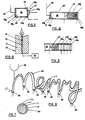
- FIG. 3 shows a third type of the switching means 13 which includes a pressure sensitive switch 21.
- a sealed container 23 is closed at one end 23 a by a flexible or elastic membrane 24, and contains thermally expansible material 25, for example air.
- a thermally conducting wire 26 extends from the region of the candle flame 8 into the other end 23 b of the container 23 where the wire 26 is laid as a flat spiral 26b on a thermally insulating plate 27. Head from the candle flame passes along the wire 26, to heat the material (air) 25 which thus expands and bows the membrane 24 outwards.
- the pressure sensitive switch 21 comprises movable and stationary contacts 28 a and 28 b .
- the movable contact 28 a is located on the membrane 24, and is arranged to contact the stationary contact 28 b when the membrane 24 is sufficiently bowed.
- the pressure sensitive switch 21, when closed, will trigger the integrated circuit IC to play a tune.
- Figure 4 shows a second embodiment of a switch mechanism, similar to that of figure 3.
- a piston 30 and cylinder 23 ⁇ arrangement is provided in place of the membrane 24, a piston 30 and cylinder 23 ⁇ arrangement is provided.
- the piston 30 As the air 25 in the cylinder 23 ⁇ expands, the piston 30 is urged along the cylinder 23 against the biassing force of spring 31, the end 23a of the cylinder having aperture 31.
- Piston 30 carries a first switch contact 28a ⁇ and a second switch contact 28b ⁇ is mounted at the cylinder end 23a.
- the wire 26 heats the air 25 to a sufficient extent the piston is pushed to the end of the cylinder against the force of spring 31, closing the switch contacts 28a ⁇ , 28b ⁇ together.
- Figure 5 shows a modification of the embodiment of figure 4 in which several switch contacts 28b ⁇ are arranged along the cylinder 23. As the temperature of the air 25 increases the piston is pushed further along the cylinder and contact 28a ⁇ makes contact with each contact 28b ⁇ in turn. Each contact 28b ⁇ forms an input to the IC, and the IC is arranged to play a number of different tunes. As contact is made between contact 28a ⁇ and each contact 28b ⁇ in turn a different tune is played by the IC.
- FIG. 6 shows a switch mechanism which operates independently of the candle.
- An elongate glass tube 40 is formed into the shape of a word.
- the tupe 40 is packed with a mix 41 of porous material and copper (11) sulphate crystals.
- water is poured into a reservoir 42 at one end of the tube 40.
- the water is slowly absorbed along the tube by the porous material.
- the copper (11) sulphate crystals contacts 43 are fixed in the tube at intervals along its length.
- the opposed contacts form plates of a capacitor. As the water reaches the contacts, the capacitance between them changes, and this can be detected by the IC, to trigger the IC to play a tune.
- Each contact is preferably arranged to trigger the playing of a different tune, or the same tune may be repeated.
- Apertures 44 in the top of the tube allow for the water to evaporate after use, so that the switch reusable.
- a heating wire 45 can be provided in the tube to dry out the mix 41.
- Figure 8 shows a candle 50 of traditional form comprising a wax body 51 having an embedded wick 52.
- a thermally conducting wire 53 extends through the body 51 adjacent the wick 52.
- the wire may extend through the centre of the wick 52.
- the wire is of low melting point so that it melts and/or burns way as the candle burns.
- Heat is conducted by the wire 53 to a sensor or switch 54 which may takes for example, the form of the switch mechanism of Figure 3, 4 or 5, a temperature sensitive resistor, or an infra red sensitive diode which reacts to infra-red light given off by the heated wire 54.
- the sensor 54 is turn triggers the IC to play a tune ( Figure 2).
- a plurality of sensors may be arranged around the candle flame, they may be fixed at different distances from the flame and/or embedded at different heights in the candle wax body. Each sensor may provide a signal for the IC, being coupled directly to the IC or activating a switch as in the embodiment of figures 3, 4 and 5.
- a manually operated on-off switch may be provided in series with the battery V to disable the music generator.
Landscapes
- Engineering & Computer Science (AREA)
- General Engineering & Computer Science (AREA)
- Fats And Perfumes (AREA)
- Arrangement Of Elements, Cooling, Sealing, Or The Like Of Lighting Devices (AREA)
- Thermally Actuated Switches (AREA)
Applications Claiming Priority (2)
| Application Number | Priority Date | Filing Date | Title |
|---|---|---|---|
| US06/931,834 US4755135A (en) | 1985-11-19 | 1986-11-18 | Candle device |
| US931834 | 1986-11-18 |
Publications (2)
| Publication Number | Publication Date |
|---|---|
| EP0268473A2 true EP0268473A2 (de) | 1988-05-25 |
| EP0268473A3 EP0268473A3 (de) | 1989-08-23 |
Family
ID=25461424
Family Applications (1)
| Application Number | Title | Priority Date | Filing Date |
|---|---|---|---|
| EP87310189A Withdrawn EP0268473A3 (de) | 1986-11-18 | 1987-11-18 | Kerzenvorrichtung |
Country Status (2)
| Country | Link |
|---|---|
| EP (1) | EP0268473A3 (de) |
| CN (1) | CN87205362U (de) |
Cited By (3)
| Publication number | Priority date | Publication date | Assignee | Title |
|---|---|---|---|---|
| GB2237579A (en) * | 1989-10-11 | 1991-05-08 | Jea Cheul Lee | Melodic candle |
| GB2318446A (en) * | 1996-10-19 | 1998-04-22 | New Union Candle Ltd | Musical Candle |
| CN111997911A (zh) * | 2020-08-27 | 2020-11-27 | 雷月兴 | 一种用于汽车工程的隔离式电动水泵 |
Family Cites Families (6)
| Publication number | Priority date | Publication date | Assignee | Title |
|---|---|---|---|---|
| DE1049806B (de) * | 1956-01-20 | 1959-02-05 | Freiburg Hermann Birmelin (Breisgau) | Sparkerze mit einer in einem Mantelrohr axial bewegbaren Kerze |
| US3762857A (en) * | 1971-12-27 | 1973-10-02 | F Andeweg | Candle internal illuminator and mount base |
| US4477249A (en) * | 1983-04-29 | 1984-10-16 | Zdenka Ruzek | Flame-producing sound-emitting device |
| JPS60102816U (ja) * | 1983-12-20 | 1985-07-13 | 株式会社 ホルス | 照明具 |
| US4568269A (en) * | 1984-12-14 | 1986-02-04 | Tung Tsan Lin | Musical candle |
| DE3618309A1 (de) * | 1985-05-31 | 1986-12-18 | Wai-Shi North Point Kwok | Kerzen |
-
1987
- 1987-11-18 EP EP87310189A patent/EP0268473A3/de not_active Withdrawn
- 1987-11-18 CN CN87205362U patent/CN87205362U/zh not_active Expired - Lifetime
Cited By (4)
| Publication number | Priority date | Publication date | Assignee | Title |
|---|---|---|---|---|
| GB2237579A (en) * | 1989-10-11 | 1991-05-08 | Jea Cheul Lee | Melodic candle |
| GB2237579B (en) * | 1989-10-11 | 1993-07-07 | Jea Cheul Lee | Melodic candle |
| GB2318446A (en) * | 1996-10-19 | 1998-04-22 | New Union Candle Ltd | Musical Candle |
| CN111997911A (zh) * | 2020-08-27 | 2020-11-27 | 雷月兴 | 一种用于汽车工程的隔离式电动水泵 |
Also Published As
| Publication number | Publication date |
|---|---|
| CN87205362U (zh) | 1988-09-14 |
| EP0268473A3 (de) | 1989-08-23 |
Similar Documents
| Publication | Publication Date | Title |
|---|---|---|
| US5057005A (en) | Candle device | |
| US4755135A (en) | Candle device | |
| EP0148854B1 (de) | Flammerregende und schallausstrahlende anordnung | |
| KR920000673Y1 (ko) | 멜로디가 나오는 1회용 케이크초 | |
| EP0146247A2 (de) | Leuchtvorrichtung | |
| US7699603B2 (en) | Multisensory candle assembly | |
| US4645910A (en) | Steam responsive thermostatic control arrangement for electric kettles | |
| EP4137741B1 (de) | Lichtempfindliche kerze | |
| US4030867A (en) | Apparatus for forming a bar of soap from leftover pieces | |
| KR880010622A (ko) | 열권선이나 할로겐램프로 과열되는 유리세라믹 평판인, 한 물질의 온도조절장치 | |
| US5487658A (en) | Safety device for novelty candle holders | |
| US5444227A (en) | Heater apparatus for use in a liquid environment | |
| KR20060096798A (ko) | 물질의 온도 및 특성 등에 의해 음악을 울려 주는 매직 음악 컵 또는 용기 | |
| EP0268473A3 (de) | Kerzenvorrichtung | |
| DK0841192T3 (da) | Anordning til termisk indbindning af ark | |
| US5910263A (en) | Device for binding sheets by heating | |
| RU96118387A (ru) | Система пожаротушения | |
| US2898439A (en) | Control device | |
| KR200202111Y1 (ko) | 재백효과를 감지장치로 이용한 멜로디 양초 | |
| CA1284341C (en) | Vaporizing unit | |
| JP2006154920A (ja) | 自動火災報知器 | |
| JPS6253618A (ja) | 旋律音を発する煮沸器 | |
| JPH11118488A5 (de) | ||
| JPH0312682Y2 (de) | ||
| JPH02290426A (ja) | 加熱調理器 |
Legal Events
| Date | Code | Title | Description |
|---|---|---|---|
| PUAI | Public reference made under article 153(3) epc to a published international application that has entered the european phase |
Free format text: ORIGINAL CODE: 0009012 |
|
| AK | Designated contracting states |
Kind code of ref document: A2 Designated state(s): DE FR GB NL |
|
| PUAL | Search report despatched |
Free format text: ORIGINAL CODE: 0009013 |
|
| AK | Designated contracting states |
Kind code of ref document: A3 Designated state(s): DE FR GB NL |
|
| 17P | Request for examination filed |
Effective date: 19900118 |
|
| 17Q | First examination report despatched |
Effective date: 19911122 |
|
| STAA | Information on the status of an ep patent application or granted ep patent |
Free format text: STATUS: THE APPLICATION IS DEEMED TO BE WITHDRAWN |
|
| 18D | Application deemed to be withdrawn |
Effective date: 19920403 |