EP0268514B1 - Vorrichtung zum Einstellen der Höhe und der Sitzfläche eines Sitzes, insbesondere eines Fahrzeugsitzes - Google Patents
Vorrichtung zum Einstellen der Höhe und der Sitzfläche eines Sitzes, insbesondere eines Fahrzeugsitzes Download PDFInfo
- Publication number
- EP0268514B1 EP0268514B1 EP87402383A EP87402383A EP0268514B1 EP 0268514 B1 EP0268514 B1 EP 0268514B1 EP 87402383 A EP87402383 A EP 87402383A EP 87402383 A EP87402383 A EP 87402383A EP 0268514 B1 EP0268514 B1 EP 0268514B1
- Authority
- EP
- European Patent Office
- Prior art keywords
- cam plate
- runner
- base
- cam
- seat
- Prior art date
- Legal status (The legal status is an assumption and is not a legal conclusion. Google has not performed a legal analysis and makes no representation as to the accuracy of the status listed.)
- Expired - Lifetime
Links
- 238000005096 rolling process Methods 0.000 claims description 14
- 239000002184 metal Substances 0.000 claims description 6
- 239000000463 material Substances 0.000 claims description 3
- 239000004033 plastic Substances 0.000 claims description 3
- 238000004513 sizing Methods 0.000 claims 1
- 230000007246 mechanism Effects 0.000 description 5
- 238000004519 manufacturing process Methods 0.000 description 4
- 230000001419 dependent effect Effects 0.000 description 1
- 238000006073 displacement reaction Methods 0.000 description 1
- 239000002991 molded plastic Substances 0.000 description 1
Images



Classifications
-
- B—PERFORMING OPERATIONS; TRANSPORTING
- B60—VEHICLES IN GENERAL
- B60N—SEATS SPECIALLY ADAPTED FOR VEHICLES; VEHICLE PASSENGER ACCOMMODATION NOT OTHERWISE PROVIDED FOR
- B60N2/00—Seats specially adapted for vehicles; Arrangement or mounting of seats in vehicles
- B60N2/02—Seats specially adapted for vehicles; Arrangement or mounting of seats in vehicles the seat or part thereof being movable, e.g. adjustable
- B60N2/04—Seats specially adapted for vehicles; Arrangement or mounting of seats in vehicles the seat or part thereof being movable, e.g. adjustable the whole seat being movable
- B60N2/16—Seats specially adapted for vehicles; Arrangement or mounting of seats in vehicles the seat or part thereof being movable, e.g. adjustable the whole seat being movable height-adjustable
- B60N2/1605—Seats specially adapted for vehicles; Arrangement or mounting of seats in vehicles the seat or part thereof being movable, e.g. adjustable the whole seat being movable height-adjustable characterised by the cinematic
- B60N2/163—Slides only
-
- B—PERFORMING OPERATIONS; TRANSPORTING
- B60—VEHICLES IN GENERAL
- B60N—SEATS SPECIALLY ADAPTED FOR VEHICLES; VEHICLE PASSENGER ACCOMMODATION NOT OTHERWISE PROVIDED FOR
- B60N2/00—Seats specially adapted for vehicles; Arrangement or mounting of seats in vehicles
- B60N2/02—Seats specially adapted for vehicles; Arrangement or mounting of seats in vehicles the seat or part thereof being movable, e.g. adjustable
- B60N2/04—Seats specially adapted for vehicles; Arrangement or mounting of seats in vehicles the seat or part thereof being movable, e.g. adjustable the whole seat being movable
- B60N2/16—Seats specially adapted for vehicles; Arrangement or mounting of seats in vehicles the seat or part thereof being movable, e.g. adjustable the whole seat being movable height-adjustable
- B60N2/1635—Seats specially adapted for vehicles; Arrangement or mounting of seats in vehicles the seat or part thereof being movable, e.g. adjustable the whole seat being movable height-adjustable characterised by the drive mechanism
- B60N2/164—Linear actuator, e.g. screw mechanism
Definitions
- the subject of the present invention is a device for adjusting the height and the attitude of a seat, in particular of a vehicle, of the type comprising slides movable longitudinally on the floor of the vehicle, a seat supporting a cushion and a backrest, and means for adjusting the seat height and attitude.
- this type of riser is inconvenient since it is only by successive approximations that it is possible to separately adjust the height and the inclination, or trim, of the seat.
- an adjustment mechanism makes it possible to tilt the seat only around transverse axes passing through its front edge or its rear edge.
- This known adjustment device therefore does not make it possible to give the trim such a tilting movement around this axis.
- the object of the invention is to produce an adjustment device of the type with two independent raising and attitude movements, making it possible to obtain an attitude trajectory corresponding exactly to that desired, which is of reduced bulk compared to the devices. earlier, simpler to manufacture, therefore less expensive, and which almost completely eliminates any elasticity of the mechanism by generating clearances or vibrations.
- the cam is formed by a plate in which are formed at least two elongated and inclined openings, the upper edges of which constitute the bearing tracks of the cam on rolling or sliding members mounted on supports integral with the slide.
- the support tracks of the seat on the cam are formed by the lower edges of at least two inclined elongated slots, produced in the cam and profiled in correlation with the movement of the attitude sought, preferably a tilting of the seat around a horizontal transverse axis crossing at a determined height the location reserved for the passenger, the seat being equipped with rolling or sliding members which cooperate with said support tracks of the seat on the cam.
- the lights allowing the height adjustment of the cam and the seat are normally rectilinear and inclined on a horizontal plane, while the lights formed in the cam to allow the movement of the seat plate have a geometry directly dependent on the inclination movement sought for the seat, which effectively makes it possible to obtain the exact trajectory sought for the attitude movement.
- each of the two cams of this device can be constituted by a molded or cut metal part, or by a molded plastic part armed with a wire mesh or by a welded wire mesh, the manufacture of which is relatively simple. and inexpensive.
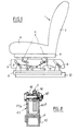
- a seat 1 of a motor vehicle comprising a backrest 2 and a cushion 3, which rests on a seat 4 mounted in abutment on a complex cam 5, itself supported by a movable slide 6 forming a base and capable of slide longitudinally on a fixed slide 10 secured to the vehicle floor.
- the entire mechanism includes two cams 5 and two similar slides 6, placed on each side of the seat 1, and secured together by the upper structure of the seat (seat 4) and, where appropriate, by cross bars not shown.
- the cam 5 is constituted by a metal sheet molded or cut, or by a sheet molded in plastic material and armed with a welded wire mesh or by a welded wire mesh.
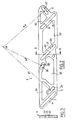
- On each cam 5 are provided, on the one hand tracks 7, 8 for supporting the cam 5 on the slide 6 for the height adjustment of the cam 5 and the seat 4, and on the other hand tracks 9, 11 for supporting the seat 4 on the cam 5, profiled as a function of the desired plate movement for the seat 4 relative to the cam 5.
- the device further comprises control means, on the one hand of the height of the cam 5 and of the seat 4 relative to the slide 6, and on the other hand of the base of the seat 4 relative to to the cam 5.
- these means are formed. for adjusting the height of the cam 5, by a jack 12 anchored on the one hand on the slide 6 and on the other hand on the cam 5, and, for adjusting the seat inclination of the seat 4, by a jack 13 anchored on the cam 5 and on the seat 4.
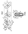
- the cam 5 In the cam 5 are formed several openings 20, 30, 40, 50 and, in the vicinity of the front and rear ends, at least two elongated rectilinear openings 14, 15, inclined on the horizontal with the same inclination.
- the respective upper edges 7, 8 of the slots 14, 15 constitute the bearing tracks of the cam 5 on rollers 16, 17 of rolling mounted on supports constituted by yokes 41, 18 fixed to the slide 6.
- Each roller or roller 16, 17 is mounted on an axis 19 ( Figure 8) passing through two cheeks 41 a, 41 b of the yoke 41.
- the cam 5 and the jack 12 are placed between the cheeks 41 a, 41 b.
- the support of the cam 5 on the rollers 16, 17 is therefore made by the upper edges 7, 8 constituting the height adjustment tracks of the cam 5.
- a second elongated straight slot 21 similar to the slots 14, 15 and of the same inclination, the edge of which lower 22 constitutes a counter-track for adjusting the height of the cam 5.
- this counter-track 22 comes to bear a rolling roller 23, mounted similarly to the rollers 16, 17 in a yoke 24 fixed to the slide 6 between the yokes 17 and 18.
- the mounting of the roller 23 is carried out in such a way that it is in abutment, not on the upper edge 25 of the slot 21, but on its lower edge 22 forming the backing track. This can be obtained by appropriate relative positioning of the roller 23 and the backing track 22, or by elastic means (not shown) arranged to exert on the cam 5 a restoring force directed upwards and keeping this cam in support. by the counter-track 22 on the roller 23.
- This assembly makes it possible to eliminate any play or vibration of the cam 5 with respect to the slide 6 which could arise from the fact that there is necessarily a play (visible in FIG. 8) between the rollers 16, 17 and the edges. lower lights 14, 15.
- the cylinder 12 is double-acting and its two rods 12 a, 12 b are respectively articulated on the axis 19 of the roller 16 and on a point of the lower part of the cam 5, the rod 12b being interposed between the two cheeks of the yoke 24. Furthermore, the cam 5 is also located between the cheeks of the third yoke 18. From the low position of the cam 5 ( Figure 4), the jack 12 works in traction to bring the cam 5 into position high ( Figure 5), by rolling the two rollers 16, 17 on the tracks 7, 8 and the central roller 23 on the backing track 22, the rods 12 a, 12 b being retracted.
- the tracks 9, 11 for supporting the seat 4 on the cam 5 are formed by the lower edges of at least two elongated and inclined slots 26, 27, produced in the cam 5 , preferably in the vicinity of the ends thereof.
- the slots 26, 27 are profiled in correlation with the desired trim movement, preferably as indicated above, a tilting of the seating 4 around a horizontal transverse axis passing through a point H situated at a determined height in the space reserved for the passenger.
- the openings 26, 27, therefore the support tracks 9, 11 are curved and have respective radii of curvature Ri, R2 for tilting the seat 4 around the axis passing through H.
- the seat 4 is equipped with two front 28 and rear 29 yokes carrying at their lower ends rollers 31 which bear on the tracks 9 and 11.
- a third elongated lumen 32 having a curvature corresponding to a radius R3 of tilting around H, and the upper edge 33 of which constitutes a counter-track on which a bearing roller 34 is held in abutment carried by a yoke 35 integral with the seat 4.
- the support of the roller 34 on the backing track 33 is obtained in the same manner as the support of the roller 23 on the backing track 22 and for the same purpose, in order to remove any play or vibration between the seat 4 and the cam 5.
- the control of the inclination of the seat 4 can be obtained, in the example described, by a double-acting cylinder 13, a first rod 37 of which is anchored on the cam 5 and the second rod of which 38 is articulated on the seat 4, preferably on the axis of one of the rollers 31, namely the rear roller 31 in the example described ( Figures 6-7).
- the rod 37 can be articulated on the same axis as the rod 12b of the jack 12, which simplifies the mounting of the jacks.
- the cam 5 is arranged between the cheeks of the yokes 28, 29 as well as the rod 38.
- each jack 13 associated with a cam 5 allows the seat 4 to follow an inclination movement determined by the radii of curvature R1, R2, R3 of the tracks 9, 11 and the counter-track 33, of an angular amplitude a between the maximum tilting position backwards (FIG. 6) and the maximum tilting position forward (FIG. 7).
- the second embodiment of the invention illustrated in Figures 9 to 12, has the essential advantage of reducing the size of the adjustment device compared to the previous embodiment.
- the cam 51 here comprises two elongated slots 52, 53, inclined at the same angle on the horizontal, formed at the two ends of the cam, and the slide 54 also has two slots 55, 56 elongated and inclined like the slots 52, 53 and formed opposite the latter, the upper and lower edges of these various slots being rectilinear and situated in the parallel planes.
- the two slots 52, 55 are crossed by a roller 57 rotatably mounted on a transverse axis 58, also passing through the two slots 52, 55.
- a double link 59 comprising two parallel parallel elements 59a, 59b disposed on each side of the cam 51 and of the slide 54, is articulated on the end of the axis 58 which crosses said elements 59a, 59b (FIG. 12), so as to be able to tilt around the axis 58.
- the two ends of the elements 59a, 59b are connected by transverse fingers 61, 62 which can slide perpendicular to the axis 58, remaining parallel to the latter, in openings 63, 64 arranged in the ends of the elements 59a, 59b and in corresponding openings in the cam 51 and in the slide 54. Furthermore, the roller 57 can roll simultaneously on the cam 51 by a support track 65 formed by the upper edge of the slot 52, and on the slide 54 by a support track 66 formed pa the lower edge of the light 55.
- a double-acting cylinder 67 has its two rods 68, 69 articulated respectively on the cam 51 and on an axis 71, integral with the slide 54, the articulation of the rod 68 preferably being, as shown in FIGS. 11 and 12, a lateral extension 72 upper finger 61.
- the slide 54 consists of two parallel plates 54a extended at their upper part by a yoke formed by two parallel cheeks 54b crossed by the axis 58 and by the roller 57, the cam 51 coming to come between the two cheeks 54b and between the elements 59a, 59b of the link 59.
- a second roller 73 rotatably mounted on an axis 74 crosses, as well as this, the two parallel cheeks 75 of a yoke of the slide 54, similar to yoke 54b.
- the axis 74 and the roller 73 therefore pass through the two openings 53, 56, the axis 74 being secured to the cam 51.
- the mounting of the roller 73, and its dimensioning as well as that of the lights 53, 56 are such that the roller 73 rolls on a support track 76 formed by the lower edge of the light 56 of the slide 54, and simultaneously on a second support track 77 formed by the upper edge of the light 53 of the cam 51.
- the rectilinear tracks 76, 77 are parallel to each other and to the corresponding tracks 66 and 65.
- this comprises a third yoke 78, similar to the two yokes 54b and 75, and in each of the cheeks of which a light 79 is formed, similar to the lights 55 and 56.
- a light 81 elongated and inclined, similar to lights 52 and 53, is arranged in the cam 51 opposite the light 79.
- a roller 82 is rotatably mounted on an axis 83 integral with the cam 51, these two elements passing through the two cheeks of the yoke 78 and the cam 51.
- the dimensions of the lights 79, 81 and the mounting of the roller 82 are produced so that the latter rolls in abutment on a first backing track 84 formed by the lower edge of the light 81 of the cam 51, and pressing on a second backing track 85 formed by the upper edge of the lumen 79 of the slide 54.
- This arrangement is intended to eliminate practically any play between the cam 51 and the slide 54, which would appear if the device don't understand was that the lights 52, 55 with their roller 57 and the lights 53, 56 with their roller 73.
- Figure 9 shows the cam 51 in the low position on the slide 54.
- the three rollers 57, 73, 82 are supported on the rounded lower ends of the slots 55, 56, 79 of the slide 54, and in bearing against the rounded upper ends of the slots 52, 53, 81 of the cam 51, the rods 68, 69, of the jack 67 being retracted to the maximum.
- the cam 51 has therefore traversed a complete raising stroke, while the rollers 57, 73, 82 have only traversed a half stroke in height, thanks to the simultaneity of their rolling on the tracks and counter-tracks and their displacement in height.
- the fingers 61, 62 slide in the respective openings 63, 64 and in those of the cam 51 and of the slide 54, thus allowing variations in distance between the direction of movement D of the roller 57 and fingers 61, 62.
- the number of lights formed respectively in the cam 51 and in the slide 54 could be reduced to one, with consequently a single roller 57, the roller 73 and the lights 53, 56 being eliminated, the lights as well as the roller and the associated biel lette being suitably positioned.
- the second roller 82 and its support counter tracks would then be maintained.
- the jack 67 could be replaced by any other equivalent control means, allowing the movement to raise the cam 51.
- the vertical size of such an adjustment device corresponds to half the height of a cam such as that of FIGS. 2 to 8.
- the device for adjusting the height and the attitude of the seat according to the invention is particularly suitable for its use on a car seat, in which the available spaces are extremely reduced, thanks to its small size compared to that known devices.
- Another essential advantage of the invention consists in the fact that it makes it possible to separate the attitude trajectory of the seat from the kinematics of the latter, since it is indeed possible to obtain any desired attitude trajectory from a geometry corresponding tracks and counter tracks formed in the cam. In this way, it is certain to obtain the exact trajectory sought for the seat, and this by means of cams of excellent rigidity and a minimum bulk.
- cams 5 in folded sheet metal, by molded or forged parts, or in plastic material reinforced with lattice, or in a mechanically welded lattice, considerably simplifies the manufacture of the device compared with that of previous embodiments. This also makes it possible to significantly reduce the original clearances as well as those due to wear, by virtually eliminating the vibrations and operating inaccuracies liable to cause discomfort for the seat user.
- the number of tracks required for each movement can be reduced to one or more than two.
- at least one counter-track is provided for each movement.
- the rollers or rollers 16, 17, 23, 31 can be replaced by sliding shoes, although the performance is in this case slightly less good because of the replacement of the bearing by friction.
- the lights formed in the cam 5 could be replaced by ramps or projecting ribs, preferably made integrally with the cam, and the indication of these lights or guide ramps may vary.
- the jacks 12, 13, 67 can be replaced by motorized gears, associated with racks mechanically linked to the cams 5 and to the slides 6.
- the invention is applicable to seats other than vehicles.
Landscapes
- Engineering & Computer Science (AREA)
- Aviation & Aerospace Engineering (AREA)
- Transportation (AREA)
- Mechanical Engineering (AREA)
- Seats For Vehicles (AREA)
- Chairs For Special Purposes, Such As Reclining Chairs (AREA)
Claims (15)
Applications Claiming Priority (2)
| Application Number | Priority Date | Filing Date | Title |
|---|---|---|---|
| FR8615421A FR2605948B1 (fr) | 1986-11-05 | 1986-11-05 | Dispositif de reglage de la hauteur et de l'assiette d'un siege, notamment de vehicule |
| FR8615421 | 1987-11-05 |
Publications (2)
| Publication Number | Publication Date |
|---|---|
| EP0268514A1 EP0268514A1 (de) | 1988-05-25 |
| EP0268514B1 true EP0268514B1 (de) | 1990-10-10 |
Family
ID=9340551
Family Applications (1)
| Application Number | Title | Priority Date | Filing Date |
|---|---|---|---|
| EP87402383A Expired - Lifetime EP0268514B1 (de) | 1986-11-05 | 1987-10-22 | Vorrichtung zum Einstellen der Höhe und der Sitzfläche eines Sitzes, insbesondere eines Fahrzeugsitzes |
Country Status (9)
| Country | Link |
|---|---|
| US (1) | US4781414A (de) |
| EP (1) | EP0268514B1 (de) |
| JP (1) | JPS63184532A (de) |
| BR (1) | BR8705925A (de) |
| CA (1) | CA1276538C (de) |
| DE (1) | DE3765522D1 (de) |
| ES (1) | ES2028899T3 (de) |
| FR (1) | FR2605948B1 (de) |
| MX (1) | MX160261A (de) |
Families Citing this family (13)
| Publication number | Priority date | Publication date | Assignee | Title |
|---|---|---|---|---|
| DE4224458A1 (de) * | 1992-07-24 | 1994-01-27 | Brose Fahrzeugteile | Sitzkissenverstellung f}r Fahrzeugsitze |
| US5529275A (en) * | 1994-09-08 | 1996-06-25 | Lear Seating Corporation | Vehicle seat track assembly |
| GB2374280B (en) * | 2001-03-09 | 2003-02-26 | Visteon Global Tech Inc | Seating system for a vehicle having a deceleration sensor |
| DE202004021112U1 (de) * | 2004-09-18 | 2006-10-26 | Otto Bock Healthcare Gmbh | Fahrzeug mit in der Neigung verstellbarem Fahrersitz |
| US20080088166A1 (en) * | 2006-10-16 | 2008-04-17 | Gardiner Richard J | Aircraft seat |
| DE102007027322A1 (de) * | 2007-06-14 | 2008-12-18 | Brose Fahrzeugteile Gmbh & Co. Kommanditgesellschaft, Coburg | Schienenverstellsystem für einen Kraftfahrzeugsitz |
| US7918501B1 (en) * | 2007-07-18 | 2011-04-05 | Dennis Hawkins Hanson | Vehicle safety seat |
| FR2923769B1 (fr) * | 2007-11-19 | 2010-08-20 | Peugeot Citroen Automobiles Sa | Nez d'assise reglable. |
| CN103402813B (zh) * | 2010-12-17 | 2017-11-21 | 约翰逊控制技术公司 | 第二排车辆座椅 |
| US20140292045A1 (en) * | 2013-03-29 | 2014-10-02 | Daniel Halterman Jeffery | Mechanism for Increasing the Distance Traveled During a Forceful Change in Velocity |
| US9884684B2 (en) * | 2014-10-23 | 2018-02-06 | Gulfstream Aerospace Corporation | In-flight leveling system |
| CN107139785B (zh) * | 2017-05-23 | 2019-05-10 | 新昌县羽林街道东商机械厂 | 一种座椅高度可调节的农业机械 |
| US12497174B2 (en) * | 2023-08-24 | 2025-12-16 | B/E Aerospace, Inc. | OWEED divan with fold-down backrest for egress and inflatable restraint for occupant protection |
Family Cites Families (13)
| Publication number | Priority date | Publication date | Assignee | Title |
|---|---|---|---|---|
| US2638150A (en) * | 1951-02-07 | 1953-05-12 | Checker Cab Mfg Corp | Adjustable seat structure |
| US3243227A (en) * | 1964-03-19 | 1966-03-29 | Super Sagless Spring Corp | Recliner chair |
| US3692271A (en) * | 1971-02-24 | 1972-09-19 | Lear Siegler Inc | Adjustable seat assembly |
| DE2429019C3 (de) * | 1974-06-18 | 1980-10-02 | Metallwerk Max Brose Gmbh & Co, 8630 Coburg | Höhen- und Längsverstelleinrichtung für Sitze, insbesondere Kraftfahrzeugsitze |
| DE2456725A1 (de) * | 1974-11-30 | 1976-06-10 | Daimler Benz Ag | Laengen- und hoehenverstellbarer sitz |
| US4074886A (en) * | 1977-03-07 | 1978-02-21 | Uop Inc. | Height adjustment mechanism for a vehicle seat |
| US4194783A (en) * | 1977-03-28 | 1980-03-25 | Mohasco Corporation | Wall proximity chairs and hardware therefor |
| DE2749716A1 (de) * | 1977-11-07 | 1979-05-10 | Hammerstein Gmbh C Rob | Hoehen- und neigungsverstelleinrichtung fuer fahrzeugsitze |
| DE2836005A1 (de) * | 1978-08-17 | 1980-02-28 | Daimler Benz Ag | Vorrichtung zur verstellung eines sitzes, insbesondere in kraftfahrzeugen |
| FR2484807A1 (fr) * | 1980-06-18 | 1981-12-24 | Peugeot Cycles | Dispositif de reglage de la position de l'assise d'un siege par rapport a son support |
| DE3132235A1 (de) * | 1981-08-14 | 1983-11-10 | Brose Fahrzeugteile GmbH & Co KG, 8630 Coburg | Sitzverstellung, insbesondere fuer einen kraftfahrzeugsitz |
| JPS58156424A (ja) * | 1982-03-15 | 1983-09-17 | Honda Motor Co Ltd | 車両のシ−ト高さ調整装置 |
| US4616875A (en) * | 1983-10-17 | 1986-10-14 | Ferro Manufacturing Corporation | Adjustable seat construction |
-
1986
- 1986-11-05 FR FR8615421A patent/FR2605948B1/fr not_active Expired
-
1987
- 1987-10-22 DE DE8787402383T patent/DE3765522D1/de not_active Expired - Fee Related
- 1987-10-22 EP EP87402383A patent/EP0268514B1/de not_active Expired - Lifetime
- 1987-10-22 ES ES198787402383T patent/ES2028899T3/es not_active Expired - Lifetime
- 1987-10-26 US US07/112,785 patent/US4781414A/en not_active Expired - Lifetime
- 1987-11-04 BR BR8705925A patent/BR8705925A/pt not_active IP Right Cessation
- 1987-11-04 CA CA000550979A patent/CA1276538C/en not_active Expired - Fee Related
- 1987-11-04 MX MX9137A patent/MX160261A/es unknown
- 1987-11-04 JP JP62277530A patent/JPS63184532A/ja active Pending
Also Published As
| Publication number | Publication date |
|---|---|
| EP0268514A1 (de) | 1988-05-25 |
| JPS63184532A (ja) | 1988-07-30 |
| BR8705925A (pt) | 1988-06-14 |
| DE3765522D1 (de) | 1990-11-15 |
| ES2028899T3 (es) | 1992-07-16 |
| FR2605948A1 (fr) | 1988-05-06 |
| US4781414A (en) | 1988-11-01 |
| MX160261A (es) | 1990-01-24 |
| CA1276538C (en) | 1990-11-20 |
| FR2605948B1 (fr) | 1989-01-27 |
Similar Documents
| Publication | Publication Date | Title |
|---|---|---|
| EP0268514B1 (de) | Vorrichtung zum Einstellen der Höhe und der Sitzfläche eines Sitzes, insbesondere eines Fahrzeugsitzes | |
| EP1366987B1 (de) | In ein Bett verwandelbarer Sitz mit verformbarer Armlehne | |
| EP1092585B1 (de) | Fahrzeugsitz mit einer Halsschutzvorrichtung bei einem Heckaufprall | |
| EP1345810B1 (de) | In ein bett umwandelbarer sitz, insbesondere für ein flugzeug | |
| FR2820696A1 (fr) | Siege de vehicule dote d'un dossier rabattable | |
| FR2739947A1 (fr) | Pedalier de vehicule automobile comportant un dispositif de reglage de la hauteur et de l'orientation des pedales | |
| FR2771688A1 (fr) | Siege comportant une ceinture de securite integree | |
| EP1567378B1 (de) | Ablegbares fahrzeugdach und dazugehöriges fahrzeug | |
| EP1632389B1 (de) | Kraftfahrzeugsitz | |
| EP0458000B1 (de) | Kraftfahrzeugsitz | |
| EP1537805B1 (de) | Ruhemöbel wie ein Sofa, Sessel oder Sitz zum Gebrauch in der Nähe einer Wand. | |
| FR2775637A1 (fr) | Dispositif de reglage de positions relatives de trois sieges independants arriere d'un vehicule automobile | |
| FR2755074A1 (fr) | Dispositif de reglage en hauteur d'un accoudoir et accoudoir de vehicule automobile equipe d'un tel dispositif de reglage | |
| FR2719263A1 (fr) | Articulation de dossier pour un siège de véhicule comprenant un support d'assise et un dossier articulé à ce support. | |
| FR2789142A1 (fr) | Mecanisme de reglage, et ensemble d'assise comportant un tel mecanisme | |
| FR2718398A1 (fr) | Dispositif pour siège réglable notamment de véhicule automobile et siège équipé d'un tel dispositif. | |
| EP3634177B1 (de) | Gelenksitzvorrichtung | |
| FR2798890A1 (fr) | Repose-pieds pour vehicule automobile | |
| FR2908699A1 (fr) | Siege de vehicule automobile avec assise reglable | |
| EP0281445B1 (de) | Verstellbarer und umlegbarer Sitz, insbesondere für Fahrzeuge | |
| FR2855112A1 (fr) | Siege pliable et vehicule comportant un seige pliable encastrable sous un autre siege. | |
| EP1414668B1 (de) | Verstellbare fahrzeugsitzbank | |
| EP0156814B1 (de) | Gegliederter sitz | |
| EP1808330A2 (de) | Sitz für Kraftfahrzeug, der entlang einer ersten Achse x und einer zweiten Achse y beweglich ist, und Kraftfahrzeug, das einen solchen Sitz umfasst | |
| EP0572345B1 (de) | Armlehne für einen Vordersitz eines Fahrzeuges |
Legal Events
| Date | Code | Title | Description |
|---|---|---|---|
| PUAI | Public reference made under article 153(3) epc to a published international application that has entered the european phase |
Free format text: ORIGINAL CODE: 0009012 |
|
| AK | Designated contracting states |
Kind code of ref document: A1 Designated state(s): DE ES GB IT SE |
|
| 17P | Request for examination filed |
Effective date: 19881001 |
|
| 17Q | First examination report despatched |
Effective date: 19900117 |
|
| GRAA | (expected) grant |
Free format text: ORIGINAL CODE: 0009210 |
|
| AK | Designated contracting states |
Kind code of ref document: B1 Designated state(s): DE ES GB IT SE |
|
| ITF | It: translation for a ep patent filed | ||
| REF | Corresponds to: |
Ref document number: 3765522 Country of ref document: DE Date of ref document: 19901115 |
|
| RAP2 | Party data changed (patent owner data changed or rights of a patent transferred) |
Owner name: ROCKWELL AUTOMOTIVE BODY SYSTEMS-FRANCE EN ABREGE: |
|
| GBT | Gb: translation of ep patent filed (gb section 77(6)(a)/1977) | ||
| PLBE | No opposition filed within time limit |
Free format text: ORIGINAL CODE: 0009261 |
|
| STAA | Information on the status of an ep patent application or granted ep patent |
Free format text: STATUS: NO OPPOSITION FILED WITHIN TIME LIMIT |
|
| PGFP | Annual fee paid to national office [announced via postgrant information from national office to epo] |
Ref country code: DE Payment date: 19910822 Year of fee payment: 5 |
|
| 26N | No opposition filed | ||
| PGFP | Annual fee paid to national office [announced via postgrant information from national office to epo] |
Ref country code: GB Payment date: 19911015 Year of fee payment: 5 |
|
| PGFP | Annual fee paid to national office [announced via postgrant information from national office to epo] |
Ref country code: SE Payment date: 19911028 Year of fee payment: 5 |
|
| ITTA | It: last paid annual fee | ||
| PGFP | Annual fee paid to national office [announced via postgrant information from national office to epo] |
Ref country code: ES Payment date: 19911031 Year of fee payment: 5 |
|
| REG | Reference to a national code |
Ref country code: ES Ref legal event code: FG2A Ref document number: 2028899 Country of ref document: ES Kind code of ref document: T3 |
|
| PG25 | Lapsed in a contracting state [announced via postgrant information from national office to epo] |
Ref country code: GB Effective date: 19921022 |
|
| PG25 | Lapsed in a contracting state [announced via postgrant information from national office to epo] |
Ref country code: SE Effective date: 19921023 Ref country code: ES Free format text: LAPSE BECAUSE OF THE APPLICANT RENOUNCES Effective date: 19921023 |
|
| GBPC | Gb: european patent ceased through non-payment of renewal fee |
Effective date: 19921022 |
|
| PG25 | Lapsed in a contracting state [announced via postgrant information from national office to epo] |
Ref country code: DE Effective date: 19930803 |
|
| EUG | Se: european patent has lapsed |
Ref document number: 87402383.1 Effective date: 19930510 |
|
| REG | Reference to a national code |
Ref country code: ES Ref legal event code: FD2A Effective date: 19991007 |
|
| PG25 | Lapsed in a contracting state [announced via postgrant information from national office to epo] |
Ref country code: IT Free format text: LAPSE BECAUSE OF NON-PAYMENT OF DUE FEES;WARNING: LAPSES OF ITALIAN PATENTS WITH EFFECTIVE DATE BEFORE 2007 MAY HAVE OCCURRED AT ANY TIME BEFORE 2007. THE CORRECT EFFECTIVE DATE MAY BE DIFFERENT FROM THE ONE RECORDED. Effective date: 20051022 |