EP0268577A1 - Pelle basculante de chargement - Google Patents
Pelle basculante de chargement Download PDFInfo
- Publication number
- EP0268577A1 EP0268577A1 EP87890260A EP87890260A EP0268577A1 EP 0268577 A1 EP0268577 A1 EP 0268577A1 EP 87890260 A EP87890260 A EP 87890260A EP 87890260 A EP87890260 A EP 87890260A EP 0268577 A1 EP0268577 A1 EP 0268577A1
- Authority
- EP
- European Patent Office
- Prior art keywords
- bucket
- loading
- pressure medium
- arms
- frame
- Prior art date
- Legal status (The legal status is an assumption and is not a legal conclusion. Google has not performed a legal analysis and makes no representation as to the accuracy of the status listed.)
- Granted
Links
- 239000000725 suspension Substances 0.000 claims abstract description 6
- 238000010276 construction Methods 0.000 description 5
- 230000002349 favourable effect Effects 0.000 description 5
- 230000001771 impaired effect Effects 0.000 description 1
- 239000000463 material Substances 0.000 description 1
- 238000004904 shortening Methods 0.000 description 1
Images

Classifications
-
- B—PERFORMING OPERATIONS; TRANSPORTING
- B62—LAND VEHICLES FOR TRAVELLING OTHERWISE THAN ON RAILS
- B62D—MOTOR VEHICLES; TRAILERS
- B62D49/00—Tractors
- B62D49/02—Tractors modified to take lifting devices
-
- E—FIXED CONSTRUCTIONS
- E02—HYDRAULIC ENGINEERING; FOUNDATIONS; SOIL SHIFTING
- E02F—DREDGING; SOIL-SHIFTING
- E02F3/00—Dredgers; Soil-shifting machines
- E02F3/04—Dredgers; Soil-shifting machines mechanically-driven
- E02F3/28—Dredgers; Soil-shifting machines mechanically-driven with digging tools mounted on a dipper- or bucket-arm, i.e. there is either one arm or a pair of arms, e.g. dippers, buckets
- E02F3/34—Dredgers; Soil-shifting machines mechanically-driven with digging tools mounted on a dipper- or bucket-arm, i.e. there is either one arm or a pair of arms, e.g. dippers, buckets with bucket-arms, i.e. a pair of arms, e.g. manufacturing processes, form, geometry, material of bucket-arms directly pivoted on the frames of tractors or self-propelled machines
-
- E—FIXED CONSTRUCTIONS
- E02—HYDRAULIC ENGINEERING; FOUNDATIONS; SOIL SHIFTING
- E02F—DREDGING; SOIL-SHIFTING
- E02F3/00—Dredgers; Soil-shifting machines
- E02F3/04—Dredgers; Soil-shifting machines mechanically-driven
- E02F3/627—Devices to connect beams or arms to tractors or similar self-propelled machines, e.g. drives therefor
Definitions
- the invention relates to a loader bucket which is to be fastened to a motor vehicle, in particular an agricultural tractor via its three-point suspension, and which can be tilted about a horizontal axis oriented transversely to the direction of travel.
- a loader bucket is known from GB-A-729863.
- the well-known loader bucket can be raised and lowered via the three-point hitch of the excavator tractor.
- a lever on the top link To tilt the shovel, a lever on the top link must be operated so that the top link can extend telescopically and the loader tip bucket can be tilted down about a horizontal axis aligned transversely to the vehicle.
- the disadvantage of this known loading tipping bucket is that its stroke range is limited, and that the telescopically extendable upper link must be returned to a shortened position by hand after tipping.
- the invention has for its object to develop a loader bucket of the type mentioned so that the kinematic conditions when tilting the loader bucket are more favorable than in the prior art.
- the arrangement of the tilt axis according to the invention results in more favorable conditions when tilting the loader bucket, since the free end thereof does not lower or sinks less than in the case of the loader bucket according to GB-A-729 863 Shovel and of any material located on the shovel and the tilting axis smaller, so that the tilting is increasingly easier and can be carried out with less effort.
- the feature of claim 2 optimizes the conditions mentioned above.
- a robust and simple construction that can be particularly easily attached to a three-point suspension is characterized in claim 3.
- the construction characterized in claim 8 prevents the loader tip from completely tipping over.
- the attachment point characterized in claim 9 is preferred.
- Claim 10 indicates a particularly simple embodiment of the construction according to claim 7 and / or 8.
- Claim 11 characterizes a further embodiment, in which there are particularly favorable conditions when the loading tip bucket is tilted by the drive member, and the drive member is arranged in a particularly space-saving manner between the two arms to which the loading tip bucket is pivotally attached when the loading tip bucket is not tilted up.
- the loading and unloading bucket can be raised higher by lifting the free ends of the arms, on which it is tiltable, un, for example, also good in higher containers or the like. to be able to tip over.
- the drive member and the upper link designed as a pressure medium motor it is also possible to lift the loading and tipping bucket while maintaining a substantially horizontal position of the bucket.
- the drive members need a double-acting linear motor, but can for example be designed as a simple pressure medium motor.
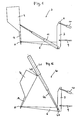
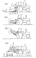
- an agricultural tractor 1 (tractor) is shown, on the three-point suspension 2, a loader bucket 3 is attached.
- the actual blade 4 is attached to the free ends 5 by two arms 6 such that it can be tilted about a horizontal axis.
- the arms 6 start from a frame 7, which is essentially triangular in shape in the direction of travel and has a lower horizontal leg and two inclined legs converging towards the tip 8.
- the frame 7 is connected at the bottom via two support struts 9 and at the top via a pressure medium motor 10 to the three-point linkage 2 of the agricultural tractor 1.
- a drive element 11 is provided, which in the present case (see in particular FIGS ) is designed as a multi-stage pressure medium motor with a telescopically extendable piston rod.
- the shovel 4 can be equipped with tines 14 on its region protruding beyond the free ends 5 of the arms 6 (see FIG. 1), which make it easier to pick up cargo.
- the loading and tipping bucket 3 can be pivoted from the position shown in FIG. 2, in which the edge of the bucket 4 facing away from the tractor 1 lies on the floor 12, by actuating the pressure medium motor 10 into the position shown in FIG. 2, in which the frame 7 is essentially perpendicular is aligned. By further shortening the pressure medium motor 10, the frame 7 can be pivoted further, so that the free ends 5 of the arms 6 are raised. This can be used, for example, to tip good out of the bucket 4, as shown in FIG. 5, into a motor vehicle or a trailer.
- the tilted position of the blade 4 is shown in dash-dot lines. From Figure 5 it can also be seen that by operating the pressure medium motors 10 and 11 together, the blade 4 can also be kept horizontal when the free ends 5 of the arms 6 are raised.
- Figures 1 to 5 show that the drive member 11 designed as a pressure medium cylinder is supported on the one hand on the lower horizontal leg of the frame 7 and on the other hand on the underside of the blade 4.
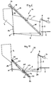
- a pressure medium cylinder 15 is seen as the drive element for tilting the bucket 4, which cylinder is located on the lower horizontal spar of the frame 4 is supported.
- a freely rotatable roller 17 is provided, via which a rope, a chain or the like. 18 is performed.
- One end 19 of the cable 18 is attached to the underside of the blade 4, while the other end 20 of the cable 18 is attached to the cylinder jacket of the pressure medium cylinder 15.
- a chain or the like is between the frame 7 and the underside of the blade 4. provided that is tensioned in the fully tilted position shown in Figure 5. By changing the length of this rope 21, it can also be determined how far the blade 4 can be tilted.
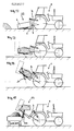
- FIGS. 7 to 10 show different possibilities for the movements of the loading and tipping bucket 13 shown in FIG. 6 with their drive element 15.
- a spring (not shown) can be provided which pulls the blade 4 back from its position shown in FIG. 6, for example, into the position according to FIG. 7, or at least initiates this return movement until the blade 4 is under its own Weight tilts back when the piston rod 16 of the drive member 15 is pulled in.
- a pressure medium cylinder 23 is provided as the drive element for tilting the blade 4.
- This pressure medium cylinder 23 is coupled via a link 24 to the arms 6, at the free ends 5 of which the blade 4 is pivotably attached.
- the links 24 are articulated to the arms 6 at 25. at their ends 26 opposite the articulation points 25, the links 24 are pivotally connected to the lower end of the pressure cylinder 23.
- At least one sliding plate 27 or a deflection roller is provided, on which a tension spring 28 (or two tension springs) rests from below, the end 29 of which on the underside of the blade 4 and the other end 30 in the region of the lower horizontal leg of the frame 7 is attached.
- the piston rod 31 of the pressure medium motor 23 also engages on the underside of the blade 4.
- the pressure medium motor 23 is completely accommodated between the arms 6 when the blade 4 (FIG. 12) is tilted into the rest position. If the pressure medium motor 23 is pressurized with pressure medium and the blade 4 begins to tilt, it assumes the positions indicated schematically in FIGS. 14 and 15, in which the points 25, 26 and the point of engagement 32 of the piston rod 31 lie in a plane 33 . This results in particularly favorable kinematic conditions when the blade 4 is tilted up without the space-saving arrangement of the pressure medium motor 23 being impaired.
- the tension spring 28 accelerates the folding back of the blade 4 or, if the drive element 23 is a single-acting pressure medium motor, makes it possible in the first place. If a double-acting pressure medium motor is used as the drive element 23, the spring 28 is not necessary.
- a multi-stage, possibly double-acting pressure medium motor 41 is provided as the drive element, which at the lower edge of the blade 4 at 42 with the blade 4 is articulated.
- the other support point 43 of the pressure medium motor 41 (whose piston rod 44) is located at the lower end of the frame 7.
- This embodiment of the loading and tipping blade 40 has the advantage that the drive member 41 is parallel to the frame 7 when the blade is not tilted up.
Landscapes
- Engineering & Computer Science (AREA)
- Mechanical Engineering (AREA)
- Mining & Mineral Resources (AREA)
- Civil Engineering (AREA)
- General Engineering & Computer Science (AREA)
- Structural Engineering (AREA)
- Chemical & Material Sciences (AREA)
- Combustion & Propulsion (AREA)
- Transportation (AREA)
- Forklifts And Lifting Vehicles (AREA)
- Shovels (AREA)
- Agricultural Machines (AREA)
- Portable Nailing Machines And Staplers (AREA)
Applications Claiming Priority (6)
| Application Number | Priority Date | Filing Date | Title |
|---|---|---|---|
| AT3080/86 | 1986-11-19 | ||
| AT308086 | 1986-11-19 | ||
| AT201887 | 1987-08-11 | ||
| AT2018/87 | 1987-08-11 | ||
| AT2414/87 | 1987-09-24 | ||
| AT241487 | 1987-09-24 |
Publications (3)
| Publication Number | Publication Date |
|---|---|
| EP0268577A1 true EP0268577A1 (fr) | 1988-05-25 |
| EP0268577B1 EP0268577B1 (fr) | 1989-12-27 |
| EP0268577B2 EP0268577B2 (fr) | 1992-10-21 |
Family
ID=27148146
Family Applications (1)
| Application Number | Title | Priority Date | Filing Date |
|---|---|---|---|
| EP87890260A Expired - Lifetime EP0268577B2 (fr) | 1986-11-19 | 1987-11-18 | Pelle basculante de chargement |
Country Status (3)
| Country | Link |
|---|---|
| EP (1) | EP0268577B2 (fr) |
| AT (1) | ATE48979T1 (fr) |
| DE (1) | DE3761249D1 (fr) |
Cited By (2)
| Publication number | Priority date | Publication date | Assignee | Title |
|---|---|---|---|---|
| WO1992013693A1 (fr) * | 1991-01-31 | 1992-08-20 | Costa Goncalves Antonio Da | Engin de chantier multifonctions |
| DE202019001266U1 (de) * | 2019-03-19 | 2020-06-25 | Agria-Werke Gmbh | Landwirtschaftliches Tragfahrzeug mit einer Verbindungsvorrichtung und Landwirtschaftsfahrzeug |
Citations (4)
| Publication number | Priority date | Publication date | Assignee | Title |
|---|---|---|---|---|
| GB729863A (en) * | 1952-08-26 | 1955-05-11 | Jerimiah John Smith | Improvements in or relating to platforms for attachment to tractors |
| AT187797B (de) * | 1939-11-25 | 1956-11-26 | Henry George Ferguson | Vorrichtung zur Verbindung eines Einachsanhängers mit der Zugmaschine |
| AT189935B (de) * | 1946-11-25 | 1957-05-25 | Ferguson Harry Inc | Schlepper mit einer motorisch getriebenen Hebeeinrichtung und einem damit verbundenen Hebegestänge zum Halten von Geräten |
| DE3107228A1 (de) * | 1981-02-26 | 1982-09-23 | Deere & Co., Moline, Ill., US, Niederlassung Deere & Co. European Office, 6800 Mannheim | Kraftfahrzeug, insbesondere ackerschlepper |
-
1987
- 1987-11-18 EP EP87890260A patent/EP0268577B2/fr not_active Expired - Lifetime
- 1987-11-18 DE DE8787890260T patent/DE3761249D1/de not_active Expired - Fee Related
- 1987-11-18 AT AT87890260T patent/ATE48979T1/de active
Patent Citations (4)
| Publication number | Priority date | Publication date | Assignee | Title |
|---|---|---|---|---|
| AT187797B (de) * | 1939-11-25 | 1956-11-26 | Henry George Ferguson | Vorrichtung zur Verbindung eines Einachsanhängers mit der Zugmaschine |
| AT189935B (de) * | 1946-11-25 | 1957-05-25 | Ferguson Harry Inc | Schlepper mit einer motorisch getriebenen Hebeeinrichtung und einem damit verbundenen Hebegestänge zum Halten von Geräten |
| GB729863A (en) * | 1952-08-26 | 1955-05-11 | Jerimiah John Smith | Improvements in or relating to platforms for attachment to tractors |
| DE3107228A1 (de) * | 1981-02-26 | 1982-09-23 | Deere & Co., Moline, Ill., US, Niederlassung Deere & Co. European Office, 6800 Mannheim | Kraftfahrzeug, insbesondere ackerschlepper |
Cited By (3)
| Publication number | Priority date | Publication date | Assignee | Title |
|---|---|---|---|---|
| WO1992013693A1 (fr) * | 1991-01-31 | 1992-08-20 | Costa Goncalves Antonio Da | Engin de chantier multifonctions |
| US5261739A (en) * | 1991-01-31 | 1993-11-16 | Da Costa Goncalves Antonio | Multifunction construction machine |
| DE202019001266U1 (de) * | 2019-03-19 | 2020-06-25 | Agria-Werke Gmbh | Landwirtschaftliches Tragfahrzeug mit einer Verbindungsvorrichtung und Landwirtschaftsfahrzeug |
Also Published As
| Publication number | Publication date |
|---|---|
| EP0268577B1 (fr) | 1989-12-27 |
| DE3761249D1 (de) | 1990-02-01 |
| ATE48979T1 (de) | 1990-01-15 |
| EP0268577B2 (fr) | 1992-10-21 |
Similar Documents
| Publication | Publication Date | Title |
|---|---|---|
| DE813494C (de) | Ladevorrichtung an Motorschleppern | |
| DE3047132A1 (de) | Mehrzweckfahrzeug | |
| DE2719564A1 (de) | Klappwand fuer einen von der rueckseite beladbaren muellastwagen o.dgl. | |
| DE69122933T2 (de) | Senkrechtausleger für Hublader | |
| DE2324690A1 (de) | Gestaenge fuer in der hoehe entladende eimer | |
| DE2406342A1 (de) | Scherenrahmen, insbesondere fuer kippfahrzeuge | |
| DE102013209906A1 (de) | Gabelträgerneigung | |
| EP0268577B1 (fr) | Pelle basculante de chargement | |
| EP0563513B1 (fr) | Dispositif de levage d'outil pour chargeurs | |
| EP1045941A1 (fr) | Machine de chargement mobile a equipement de chargement frontal | |
| WO2002095142A1 (fr) | Excavatrice sur roues | |
| DE1915432C3 (de) | Ladefahrzeug mit an ausziehbaren Schwenkholmen kippbarer Schrappschaufel, insbesondere für die Stallentmistung | |
| DE2230166C2 (de) | Schürfkübelfahrzeug | |
| DE3013179A1 (de) | Schaufelkoppvorrichtung | |
| DE1949385A1 (de) | Ladevorrichtung | |
| DE1230366B (de) | Planiergeraet | |
| DE2931864A1 (de) | Kippschaufel fuer gabelhubstapler | |
| DE3341614C2 (de) | Schaufellader mit einer Schaufelkippvorrichtung | |
| EP0039050A1 (fr) | Benne racleuse pour véhicule avec pelle frontale | |
| DE2338426A1 (de) | Transport-schaufelradlader | |
| DE19646860C2 (de) | Zweirädriges Hubgerät für insbesondere auf Paletten ruhende Lasten, wie z.B. Baumaterial o.dgl. | |
| DE10029482C1 (de) | Vorrichtung zum Rücken von Stammholz oder dergleichen | |
| DE29510800U1 (de) | Ladewagen zur Beförderung von insbesondere Erntegut | |
| DE19539945B4 (de) | Flurförderzeug mit einer aus mindestens zwei Gabelzinken gebildeten Gabel | |
| DE2354589A1 (de) | Wagenheber |
Legal Events
| Date | Code | Title | Description |
|---|---|---|---|
| PUAI | Public reference made under article 153(3) epc to a published international application that has entered the european phase |
Free format text: ORIGINAL CODE: 0009012 |
|
| AK | Designated contracting states |
Kind code of ref document: A1 Designated state(s): AT CH DE FR IT LI |
|
| 17P | Request for examination filed |
Effective date: 19880331 |
|
| 17Q | First examination report despatched |
Effective date: 19890427 |
|
| GRAA | (expected) grant |
Free format text: ORIGINAL CODE: 0009210 |
|
| AK | Designated contracting states |
Kind code of ref document: B1 Designated state(s): AT CH DE FR IT LI |
|
| REF | Corresponds to: |
Ref document number: 48979 Country of ref document: AT Date of ref document: 19900115 Kind code of ref document: T |
|
| REF | Corresponds to: |
Ref document number: 3761249 Country of ref document: DE Date of ref document: 19900201 |
|
| ITF | It: translation for a ep patent filed | ||
| ET | Fr: translation filed | ||
| PLBI | Opposition filed |
Free format text: ORIGINAL CODE: 0009260 |
|
| 26 | Opposition filed |
Opponent name: PETER SCHEIBELHOFER Effective date: 19900922 |
|
| ITTA | It: last paid annual fee | ||
| PUAH | Patent maintained in amended form |
Free format text: ORIGINAL CODE: 0009272 |
|
| STAA | Information on the status of an ep patent application or granted ep patent |
Free format text: STATUS: PATENT MAINTAINED AS AMENDED |
|
| 27A | Patent maintained in amended form |
Effective date: 19921021 |
|
| AK | Designated contracting states |
Kind code of ref document: B2 Designated state(s): AT CH DE FR IT LI |
|
| REG | Reference to a national code |
Ref country code: CH Ref legal event code: AEN |
|
| ITF | It: translation for a ep patent filed | ||
| ET3 | Fr: translation filed ** decision concerning opposition | ||
| PGFP | Annual fee paid to national office [announced via postgrant information from national office to epo] |
Ref country code: FR Payment date: 19931124 Year of fee payment: 7 Ref country code: CH Payment date: 19931124 Year of fee payment: 7 |
|
| PGFP | Annual fee paid to national office [announced via postgrant information from national office to epo] |
Ref country code: AT Payment date: 19931126 Year of fee payment: 7 |
|
| PGFP | Annual fee paid to national office [announced via postgrant information from national office to epo] |
Ref country code: DE Payment date: 19940131 Year of fee payment: 7 |
|
| PG25 | Lapsed in a contracting state [announced via postgrant information from national office to epo] |
Ref country code: AT Effective date: 19941118 |
|
| PG25 | Lapsed in a contracting state [announced via postgrant information from national office to epo] |
Ref country code: LI Effective date: 19941130 Ref country code: CH Effective date: 19941130 |
|
| PG25 | Lapsed in a contracting state [announced via postgrant information from national office to epo] |
Ref country code: FR Effective date: 19950731 |
|
| REG | Reference to a national code |
Ref country code: CH Ref legal event code: PL |
|
| PG25 | Lapsed in a contracting state [announced via postgrant information from national office to epo] |
Ref country code: DE Effective date: 19950801 |
|
| REG | Reference to a national code |
Ref country code: FR Ref legal event code: ST |
|
| PG25 | Lapsed in a contracting state [announced via postgrant information from national office to epo] |
Ref country code: IT Free format text: LAPSE BECAUSE OF NON-PAYMENT OF DUE FEES;WARNING: LAPSES OF ITALIAN PATENTS WITH EFFECTIVE DATE BEFORE 2007 MAY HAVE OCCURRED AT ANY TIME BEFORE 2007. THE CORRECT EFFECTIVE DATE MAY BE DIFFERENT FROM THE ONE RECORDED. Effective date: 20051118 |