EP0268954B1 - Procédé pour fabriquer des articles en matière plastique comportant une partie poreuse élastique - Google Patents
Procédé pour fabriquer des articles en matière plastique comportant une partie poreuse élastique Download PDFInfo
- Publication number
- EP0268954B1 EP0268954B1 EP87116789A EP87116789A EP0268954B1 EP 0268954 B1 EP0268954 B1 EP 0268954B1 EP 87116789 A EP87116789 A EP 87116789A EP 87116789 A EP87116789 A EP 87116789A EP 0268954 B1 EP0268954 B1 EP 0268954B1
- Authority
- EP
- European Patent Office
- Prior art keywords
- resin
- porous elastic
- injection
- mold
- synthetic resin
- Prior art date
- Legal status (The legal status is an assumption and is not a legal conclusion. Google has not performed a legal analysis and makes no representation as to the accuracy of the status listed.)
- Expired - Lifetime
Links
Images



Classifications
-
- B—PERFORMING OPERATIONS; TRANSPORTING
- B29—WORKING OF PLASTICS; WORKING OF SUBSTANCES IN A PLASTIC STATE IN GENERAL
- B29C—SHAPING OR JOINING OF PLASTICS; SHAPING OF MATERIAL IN A PLASTIC STATE, NOT OTHERWISE PROVIDED FOR; AFTER-TREATMENT OF THE SHAPED PRODUCTS, e.g. REPAIRING
- B29C67/00—Shaping techniques not covered by groups B29C39/00 - B29C65/00, B29C70/00 or B29C73/00
- B29C67/20—Shaping techniques not covered by groups B29C39/00 - B29C65/00, B29C70/00 or B29C73/00 for porous or cellular articles, e.g. of foam plastics, coarse-pored
-
- B—PERFORMING OPERATIONS; TRANSPORTING
- B29—WORKING OF PLASTICS; WORKING OF SUBSTANCES IN A PLASTIC STATE IN GENERAL
- B29C—SHAPING OR JOINING OF PLASTICS; SHAPING OF MATERIAL IN A PLASTIC STATE, NOT OTHERWISE PROVIDED FOR; AFTER-TREATMENT OF THE SHAPED PRODUCTS, e.g. REPAIRING
- B29C45/00—Injection moulding, i.e. forcing the required volume of moulding material through a nozzle into a closed mould; Apparatus therefor
- B29C45/14—Injection moulding, i.e. forcing the required volume of moulding material through a nozzle into a closed mould; Apparatus therefor incorporating preformed parts or layers, e.g. injection moulding around inserts or for coating articles
- B29C45/14778—Injection moulding, i.e. forcing the required volume of moulding material through a nozzle into a closed mould; Apparatus therefor incorporating preformed parts or layers, e.g. injection moulding around inserts or for coating articles the article consisting of a material with particular properties, e.g. porous, brittle
- B29C45/14795—Porous or permeable material, e.g. foam
-
- B—PERFORMING OPERATIONS; TRANSPORTING
- B29—WORKING OF PLASTICS; WORKING OF SUBSTANCES IN A PLASTIC STATE IN GENERAL
- B29C—SHAPING OR JOINING OF PLASTICS; SHAPING OF MATERIAL IN A PLASTIC STATE, NOT OTHERWISE PROVIDED FOR; AFTER-TREATMENT OF THE SHAPED PRODUCTS, e.g. REPAIRING
- B29C45/00—Injection moulding, i.e. forcing the required volume of moulding material through a nozzle into a closed mould; Apparatus therefor
- B29C45/14—Injection moulding, i.e. forcing the required volume of moulding material through a nozzle into a closed mould; Apparatus therefor incorporating preformed parts or layers, e.g. injection moulding around inserts or for coating articles
- B29C45/14467—Joining articles or parts of a single article
-
- B—PERFORMING OPERATIONS; TRANSPORTING
- B29—WORKING OF PLASTICS; WORKING OF SUBSTANCES IN A PLASTIC STATE IN GENERAL
- B29C—SHAPING OR JOINING OF PLASTICS; SHAPING OF MATERIAL IN A PLASTIC STATE, NOT OTHERWISE PROVIDED FOR; AFTER-TREATMENT OF THE SHAPED PRODUCTS, e.g. REPAIRING
- B29C45/00—Injection moulding, i.e. forcing the required volume of moulding material through a nozzle into a closed mould; Apparatus therefor
- B29C45/16—Making multilayered or multicoloured articles
-
- B—PERFORMING OPERATIONS; TRANSPORTING
- B60—VEHICLES IN GENERAL
- B60H—ARRANGEMENTS OF HEATING, COOLING, VENTILATING OR OTHER AIR-TREATING DEVICES SPECIALLY ADAPTED FOR PASSENGER OR GOODS SPACES OF VEHICLES
- B60H1/00—Heating, cooling or ventilating devices
- B60H1/00642—Control systems or circuits; Control members or indication devices for heating, cooling or ventilating devices
- B60H1/00664—Construction or arrangement of damper doors
- B60H1/00671—Damper doors moved by rotation; Grilles
-
- B—PERFORMING OPERATIONS; TRANSPORTING
- B29—WORKING OF PLASTICS; WORKING OF SUBSTANCES IN A PLASTIC STATE IN GENERAL
- B29C—SHAPING OR JOINING OF PLASTICS; SHAPING OF MATERIAL IN A PLASTIC STATE, NOT OTHERWISE PROVIDED FOR; AFTER-TREATMENT OF THE SHAPED PRODUCTS, e.g. REPAIRING
- B29C45/00—Injection moulding, i.e. forcing the required volume of moulding material through a nozzle into a closed mould; Apparatus therefor
- B29C45/14—Injection moulding, i.e. forcing the required volume of moulding material through a nozzle into a closed mould; Apparatus therefor incorporating preformed parts or layers, e.g. injection moulding around inserts or for coating articles
- B29C45/14467—Joining articles or parts of a single article
- B29C2045/14532—Joining articles or parts of a single article injecting between two sheets
-
- B—PERFORMING OPERATIONS; TRANSPORTING
- B60—VEHICLES IN GENERAL
- B60H—ARRANGEMENTS OF HEATING, COOLING, VENTILATING OR OTHER AIR-TREATING DEVICES SPECIALLY ADAPTED FOR PASSENGER OR GOODS SPACES OF VEHICLES
- B60H1/00—Heating, cooling or ventilating devices
- B60H1/00507—Details, e.g. mounting arrangements, desaeration devices
- B60H2001/006—Noise reduction
-
- B—PERFORMING OPERATIONS; TRANSPORTING
- B60—VEHICLES IN GENERAL
- B60H—ARRANGEMENTS OF HEATING, COOLING, VENTILATING OR OTHER AIR-TREATING DEVICES SPECIALLY ADAPTED FOR PASSENGER OR GOODS SPACES OF VEHICLES
- B60H1/00—Heating, cooling or ventilating devices
- B60H1/00642—Control systems or circuits; Control members or indication devices for heating, cooling or ventilating devices
- B60H1/00664—Construction or arrangement of damper doors
- B60H2001/007—Manufacturing or assembling
Definitions
- the present invention relates to a method for efficiently producing articles having a joint structure consisting of a synthetic resin portion and a portion made of a porous elastic member, such as an air duct opening/closing damper adaptable in air conditioners for automobiles, by using a synthetic resin injection molding machine.
- the present invention provides the features in the characterized part of claim 1 (first invention) and in claim 3. (second invention).
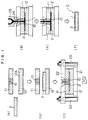
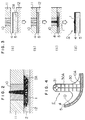
- FIGS. 1, 3 and 4 are diagrammatic illustrations of the first, second and third embodiments of the invention, illustrating the manufacturing process according to the first invention of this application as it was applied to the manufacture of an air duct opening/closing damper to be incorporated in an air conditioner for automobiles.
- FIG. 2 is a partial enlarged illustration of a step in the process of FIG. 1.
- FIG. 9 is a graphical representation of the difference in injection molding conditions between the method of this invention and a conventional method.
- a porous elastic member (hereinafter referred to as foam sheet) is set against the inner wall surface of one of the opposedly positioned splits or segments of a split injection mold and then the mold is clamped to thereby make compact the texture of the foam sheet. Then a molten synthetic resin is injected first under a low injection pressure. As the foam sheet is further compressed by the injected resin pressure, the degree of compaction of said foam sheet is raised accordingly while the resin begins to flow along the foam surface by forming an injection space. When this stage is reached, the injection pressure is adjusted stepwise to a relatively high second level.
- FIG. 1(b) illustrates the step of fitting foam sheet 2 into said cavity 12A of the lower die 12.
- FIG. 2 is a partial enlarged view of said step (d) for illustrating the proceeding of this step.
- the molten resin 1 injected from the gate 10 exerts a compressive force to the foam sheet 2 as shown by white arrows in the drawing, whereby the foam sheet 2 which has already been compressed considerably by the clamping pressure is more strongly compressed as shown in the drawing. Consequently, the porous and flexible structure of the foam sheet before compressed is strikingly changed into a very compact texture. Therefore, the molten resin which has a considerable degree of fluidity can not easily permeate into the foam sheet 2.
- FIG. 3 shows the steps in the second embodiment of this invention (first invention).
- the molded article D partially shown in section in FIG. 3(d) is a damper similar to that of the first embodiment.
- the mica-blended polypropylene resin which has been fused and plasticized by being heated to about 220°C in the injection cylinder is injected toward the surface of the laminate foam sheet 5 through the gate 10 first under a low injection pressure of about 100 kg/cm2.
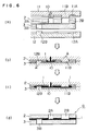
- the injection mold shown in FIG. 5(a) consists of a upper die 11 and a lower die 12, the upper die being provided with a cavity 11A and the lower die with a cavity 12A, both of said cavities being 2.2 mm in depth and equal in plane area to the foam sheets 2, 3.
- a direct gate 10 is incorporated in the upper die 11 in such a manner that the end (face) of said gate 10 projects downwardly from the split surface as shown in the drawing and will slightly get into the cavity 12A of the lower die.
- the upper foam sheet 2 is also formed with a hole 2A that allows passage of said protuberant gate end therethrough.
- the flow rate of resin during this period was about 15 mm/sec.
- the thus formed layer of molten resin is kept to an almost uniform thickness along its full length due to the balance of force between the restorative force acting against the compressive deformation of the foam sheets 2 and 3 and the pressure possessed by the injected resin (step (e)).
- the molten resin 1 which is injected from the gate 10 into the compression reducing zone A at the interface of the two foam sheets 2, 3 as in the case of the fourth embodiment impinges against the protuberance 11B or 12B positioned in the way of resin flow and flows into the compression reducing zone A where the resistance to advancing resin flow is relatively low, and as the resin flows into and advances in the compression reducing zone A encompassing the protuberance, it can easily reach the position past said protuberance. And owing to said effect of presence of the compression reducing zone A, spreading of the molten resin in the area around the protuberance is promoted and the foam sheets are prevented from being shifted or deformed.
Landscapes
- Engineering & Computer Science (AREA)
- Mechanical Engineering (AREA)
- Manufacturing & Machinery (AREA)
- Physics & Mathematics (AREA)
- Thermal Sciences (AREA)
- Injection Moulding Of Plastics Or The Like (AREA)
- Moulds For Moulding Plastics Or The Like (AREA)
- Air-Flow Control Members (AREA)
Claims (8)
- Procédé pour la production d'un article en résine synthétique (C) comportant un élément élastique poreux (2) comprenant les étapes consistant à :
placer un élément élastique poreux (2) en position contre une surface de paroi interne de l'un des segments en regard (11, 12) d'un moule d'injection divisible en deux ou plusieurs segments,
refermer le moule à injection et
comprimer l'élastique poreux (2) sous l'effet de la pression de serrage et,
injecter une résine de moulage synthétique le long de la surface de l'élément élastique poreux comprimé,
caractérisé par
le fait d'ajuster la pression d'injection de la résine pas à pas dans la plage de [(30 à 250 kg/cm²)] 295.10⁴ à 2450.10⁴ Pa en appliquant une pression permanente d'un niveau prédéterminé pendant une durée prescrite à la résine synthétique injectée dans le moule. - Procédé selon la revendication 1, dans lequel une mince pellicule (1) d'une résine synthétique thermoplastique est laminée sur le côté de l'élément élastique poreux (2) à l'endroit où la résine synthétique injectée est coulée.
- Procédé pour la production d'un article réalisé en résine synthétique (F), comprenant les étapes consistant à :
placer deux éléments élastiques poreux (2, 3) en position dans un moule à injection divisible en deux ou plusieurs segments (11, 12),
refermer le moule à injection et
comprimer les éléments élastiques poreux (2, 3) sous l'effet de la pression de serrage, procédé dans lequel une extrémité en protubérance d'une entrée (10) ménagée dans le moule est enfoncée dans les éléments élastiques de sorte que l'extrémité de l'entrée en protubérance traverse la (2) des deux éléments élastiques poreux et vient légèrement se caler dans la surface de l'autre élément élastique (3) après quoi la résine de moulage synthétique est injectée le long des faces en regard des deux éléments élastiques poreux (2, 3) la pression d'injection de la résine étant ajustée en pas à pas dans la plage de [(30 à 250 kg/cm²)] 295:10⁴ à 2450.10⁴ Pa et une pression d'un niveau prédéterminé est appliquée pendant une durée prescrite à la résine synthétique injectée dans ce moule. - Procédé selon la revendication 1 ou 3, dans lequel la pression d'injection de la résine est ajustée de telle manière que l'élément élastique poreux (2) ou les éléments (2, 3) atteignent un taux de compression dans la plage de 50 à 98%.
- Procédé selon les revendications 1 à 4 dans lequel la pression d'injection est augmentée en au moins deux étapes.
- Procédé selon les revendications 1 à 5, dans lequel l'élément élastique poreux (2) ou les éléments (2, 3) sont une mousse en résine synthétique molle.
- Procédé selon les revendications 3 à 6, dans lequel une mince pellicule (1) d'une résine synthétique thermoplastique est laminée sur les côtés en regard des deux éléments élastiques poreux (2, 3).
- Procédé selon les revendications 1 à 7, dans lequel la pression permanente ne dépasse pas [(500 kg/cm²)] 4900.10⁴.
Applications Claiming Priority (2)
| Application Number | Priority Date | Filing Date | Title |
|---|---|---|---|
| JP279245/86 | 1986-11-22 | ||
| JP61279245A JPS63205212A (ja) | 1986-11-22 | 1986-11-22 | 多孔質弾性部材を有する合成樹脂製物品の製造方法 |
Publications (3)
| Publication Number | Publication Date |
|---|---|
| EP0268954A2 EP0268954A2 (fr) | 1988-06-01 |
| EP0268954A3 EP0268954A3 (en) | 1989-12-20 |
| EP0268954B1 true EP0268954B1 (fr) | 1994-10-05 |
Family
ID=17608458
Family Applications (1)
| Application Number | Title | Priority Date | Filing Date |
|---|---|---|---|
| EP87116789A Expired - Lifetime EP0268954B1 (fr) | 1986-11-22 | 1987-11-13 | Procédé pour fabriquer des articles en matière plastique comportant une partie poreuse élastique |
Country Status (7)
| Country | Link |
|---|---|
| US (1) | US4994226A (fr) |
| EP (1) | EP0268954B1 (fr) |
| JP (1) | JPS63205212A (fr) |
| KR (1) | KR900007327B1 (fr) |
| AU (1) | AU589052B2 (fr) |
| CA (1) | CA1285728C (fr) |
| DE (1) | DE3750628T2 (fr) |
Families Citing this family (21)
| Publication number | Priority date | Publication date | Assignee | Title |
|---|---|---|---|---|
| KR960007011B1 (ko) * | 1988-01-29 | 1996-05-27 | 미쓰이세끼유 가가꾸 고오교오 가부시끼가이샤 | 적층성형체 및 그 제조방법 |
| DE3819686A1 (de) * | 1988-06-09 | 1989-12-14 | Siemens Ag | Verfahren zum umspritzen von elektrischen bauelementen mit duroplastischen kunststoffen |
| DE3836541C2 (de) * | 1988-10-27 | 1997-05-15 | Illbruck Industrieprodukte Gmb | Verfahren zur Herstellung einer Klappe für Lüftungskanäle |
| JPH0767711B2 (ja) * | 1990-08-29 | 1995-07-26 | 豊田合成株式会社 | 表皮インモールド成形品及びその成形方法 |
| US6004498A (en) * | 1994-04-04 | 1999-12-21 | Toyoda Gosei Co. Ltd. | Method for molding resin to skin members |
| US5804117A (en) * | 1994-04-05 | 1998-09-08 | Toyoda Gosei Co., Ltd. | Molding method for resin articles |
| US5690881A (en) * | 1994-05-13 | 1997-11-25 | Nippondenso Co., Ltd. | Manufacturing method of resin damper having foamed resin seal material |
| FR2723335B1 (fr) * | 1994-08-04 | 1996-10-18 | Neyr Plastiques | Procede pour la fabrication de pieces en matiere plastique comportant une portion rigide et une portion en mousse souple, et pieces obtenues par ce procede |
| JP3289546B2 (ja) * | 1995-05-16 | 2002-06-10 | 株式会社デンソー | 樹脂成形品とその製造方法 |
| JP3004198B2 (ja) * | 1995-11-14 | 2000-01-31 | ユニプレス株式会社 | 複合成形品、その製造方法および製造装置 |
| US5783228A (en) * | 1996-02-05 | 1998-07-21 | Crx Limited | Molded and laminated curved surface composites |
| JP3582262B2 (ja) * | 1996-11-15 | 2004-10-27 | 株式会社デンソー | 樹脂ケーシングおよびその製造方法 |
| JPH11254457A (ja) * | 1998-03-12 | 1999-09-21 | Idemitsu Petrochem Co Ltd | 積層成形品の成形用金型および積層成形品の製造方法 |
| DE19960494A1 (de) * | 1999-12-15 | 2001-06-21 | Knoll Ag | Vorrichtung und Verfahren zum Herstellen von festen wirkstoffhaltigen Formen |
| JP4395987B2 (ja) * | 2000-04-27 | 2010-01-13 | 株式会社デンソー | 通風路開閉用ドアの製造方法 |
| GB2366230A (en) * | 2000-08-26 | 2002-03-06 | Visteon Uk Ltd | Plastics moulding |
| DE102004014682B4 (de) * | 2004-03-25 | 2017-05-24 | Johann Borgers GmbH | Verfahren zur Herstellung eines als mindestens teilweise Verkleidung von insbesondere Schallerzeugern dienenden Verbundkörpers und Verwendung desselben |
| JP2007245552A (ja) * | 2006-03-16 | 2007-09-27 | Sumitomo Chemical Co Ltd | 熱可塑性樹脂成形品の製造方法 |
| CN101663147A (zh) * | 2007-01-30 | 2010-03-03 | 住友化学株式会社 | 热塑性树脂成形品的制造方法 |
| EP2910357A1 (fr) * | 2014-02-20 | 2015-08-26 | Basf Se | Procédé de fabrication d'un élément composite |
| JP7020188B2 (ja) * | 2018-03-02 | 2022-02-16 | トヨタ自動車株式会社 | インストルメントパネル構造 |
Family Cites Families (11)
| Publication number | Priority date | Publication date | Assignee | Title |
|---|---|---|---|---|
| US3807146A (en) * | 1967-02-21 | 1974-04-30 | H Witkowski | Mold for making a filter |
| US3493643A (en) * | 1967-04-26 | 1970-02-03 | Gilbert Schwartzman | Method for making resilient foam applicators |
| ZA703509B (en) * | 1969-06-05 | 1972-01-26 | Cav Ltd | Moulding process and apparatus |
| US4077672A (en) * | 1976-09-27 | 1978-03-07 | Tantera, Inc. | Method of making a sponge mop part |
| US4076788A (en) * | 1976-12-02 | 1978-02-28 | General Motors Corporation | Mold coating of freshly molded articles |
| JPS6124939A (ja) * | 1984-07-11 | 1986-02-03 | Nippon Denso Co Ltd | 自動車用冷暖房装置の気流制御弁及びその製造方法 |
| JPS6122914A (ja) * | 1984-07-11 | 1986-01-31 | Nippon Denso Co Ltd | 合成樹脂と繊維質シ−トとの一体成形法 |
| JPS6163445A (ja) * | 1984-09-05 | 1986-04-01 | Mitsubishi Monsanto Chem Co | 電磁波遮蔽筐体の製造方法 |
| DE3439101A1 (de) * | 1984-10-25 | 1986-05-07 | Irbit Research + Consulting Ag, Freiburg/Fribourg | Verbundkoerper-herstellungsverfahren |
| JPS6224939A (ja) * | 1985-07-25 | 1987-02-02 | Fanuc Ltd | 工作機械の切粉除けカバ− |
| FR2614827A1 (fr) * | 1987-05-06 | 1988-11-10 | Moplax | Procede pour la fabrication d'objets composes d'une partie en matiere thermoplastique et d'une partie en mousse alveolaire, et outillage pour la mise en oeuvre de ce procede |
-
1986
- 1986-11-22 JP JP61279245A patent/JPS63205212A/ja active Granted
-
1987
- 1987-11-13 DE DE3750628T patent/DE3750628T2/de not_active Expired - Lifetime
- 1987-11-13 EP EP87116789A patent/EP0268954B1/fr not_active Expired - Lifetime
- 1987-11-20 AU AU81467/87A patent/AU589052B2/en not_active Ceased
- 1987-11-20 CA CA000552310A patent/CA1285728C/fr not_active Expired - Lifetime
- 1987-11-21 KR KR1019870013135A patent/KR900007327B1/ko not_active Expired
-
1989
- 1989-08-23 US US07/397,336 patent/US4994226A/en not_active Expired - Lifetime
Also Published As
| Publication number | Publication date |
|---|---|
| EP0268954A2 (fr) | 1988-06-01 |
| US4994226A (en) | 1991-02-19 |
| AU589052B2 (en) | 1989-09-28 |
| DE3750628T2 (de) | 1995-02-16 |
| JPS63205212A (ja) | 1988-08-24 |
| KR900007327B1 (ko) | 1990-10-08 |
| KR880006036A (ko) | 1988-07-21 |
| EP0268954A3 (en) | 1989-12-20 |
| AU8146787A (en) | 1988-06-09 |
| CA1285728C (fr) | 1991-07-09 |
| JPH0360297B2 (fr) | 1991-09-13 |
| DE3750628D1 (de) | 1994-11-10 |
Similar Documents
| Publication | Publication Date | Title |
|---|---|---|
| EP0268954B1 (fr) | Procédé pour fabriquer des articles en matière plastique comportant une partie poreuse élastique | |
| WO1989005720A1 (fr) | Procede de fabrication de preformes en plastique avec un revetement decoratif de surface en relief | |
| US5690881A (en) | Manufacturing method of resin damper having foamed resin seal material | |
| EP0692358A1 (fr) | Procédé pour fabriquer une plaque en matière plastique et plaque ainsi obtenue | |
| EP1387760B1 (fr) | Procede et dispositif pour produire une piece en matiere plastique renforcee par des fibres | |
| DE3434366A1 (de) | Formwerkzeug zum herstellen von formteilen durch hinterfuellen von folienschalen mit einer kunststoff-formmasse | |
| US6419862B2 (en) | Method for the production of an expanded fiber-reinforced thermoplastic resin molding | |
| US6572808B1 (en) | Method for producing a molded laminate | |
| JP3497917B2 (ja) | 複合型樹脂成形品の製造方法及び樹脂成形用金型装置 | |
| JP3524966B2 (ja) | 樹脂成形用金型装置 | |
| JP3524984B2 (ja) | 複合型樹脂成形品の製造方法及び樹脂成形用金型装置 | |
| JP3548243B2 (ja) | 複合型熱可塑性樹脂成形品及び複合型熱可塑性樹脂成形品の製造方法 | |
| JP3445675B2 (ja) | 積層成形品の成形用金型および成形方法 | |
| JP4423138B2 (ja) | 車両用内装材の成形装置 | |
| JPH05329898A (ja) | モールの製造方法 | |
| JPH08127042A (ja) | 積層成形品および自動車用空調機の気流制御弁の製造方法 | |
| JPH0618724B2 (ja) | 自動車用内装部品の製造方法 | |
| EP1495850B1 (fr) | Appareil et procédé de fabrication d' articles des matières thermoplastiques et thermodurcissables | |
| JP2910978B2 (ja) | 樹脂成形品の製造方法およびその成形金型 | |
| JPH06190861A (ja) | モールの製造方法 | |
| JP2000025057A (ja) | 繊維強化熱可塑性樹脂膨張成形体の製造方法 | |
| JP3355756B2 (ja) | 芯材一体射出成形方法 | |
| JPH07251425A (ja) | 厚肉部分を具えたサイドモールディング及びその製造方法 | |
| JPH0350691B2 (fr) | ||
| JPH0745132B2 (ja) | 多孔質弾性部材を結合させた合成樹脂製品の製造方法 |
Legal Events
| Date | Code | Title | Description |
|---|---|---|---|
| PUAI | Public reference made under article 153(3) epc to a published international application that has entered the european phase |
Free format text: ORIGINAL CODE: 0009012 |
|
| AK | Designated contracting states |
Kind code of ref document: A2 Designated state(s): DE FR GB IT SE |
|
| PUAL | Search report despatched |
Free format text: ORIGINAL CODE: 0009013 |
|
| AK | Designated contracting states |
Kind code of ref document: A3 Designated state(s): DE FR GB IT SE |
|
| 17P | Request for examination filed |
Effective date: 19900516 |
|
| 17Q | First examination report despatched |
Effective date: 19910627 |
|
| GRAA | (expected) grant |
Free format text: ORIGINAL CODE: 0009210 |
|
| AK | Designated contracting states |
Kind code of ref document: B1 Designated state(s): DE FR GB IT SE |
|
| REF | Corresponds to: |
Ref document number: 3750628 Country of ref document: DE Date of ref document: 19941110 |
|
| ITF | It: translation for a ep patent filed | ||
| EAL | Se: european patent in force in sweden |
Ref document number: 87116789.6 |
|
| ET | Fr: translation filed | ||
| PLBI | Opposition filed |
Free format text: ORIGINAL CODE: 0009260 |
|
| 26 | Opposition filed |
Opponent name: NEYR PLASTIQUES Effective date: 19950614 |
|
| PLBF | Reply of patent proprietor to notice(s) of opposition |
Free format text: ORIGINAL CODE: EPIDOS OBSO |
|
| PLBL | Opposition procedure terminated |
Free format text: ORIGINAL CODE: EPIDOS OPPC |
|
| PLBQ | Unpublished change to opponent data |
Free format text: ORIGINAL CODE: EPIDOS OPPO |
|
| PLAB | Opposition data, opponent's data or that of the opponent's representative modified |
Free format text: ORIGINAL CODE: 0009299OPPO |
|
| PLBM | Termination of opposition procedure: date of legal effect published |
Free format text: ORIGINAL CODE: 0009276 |
|
| STAA | Information on the status of an ep patent application or granted ep patent |
Free format text: STATUS: OPPOSITION PROCEDURE CLOSED |
|
| R26 | Opposition filed (corrected) |
Opponent name: NEYR PLASTIQUES Effective date: 19950614 |
|
| 27C | Opposition proceedings terminated |
Effective date: 19961227 |
|
| REG | Reference to a national code |
Ref country code: GB Ref legal event code: IF02 |
|
| PGFP | Annual fee paid to national office [announced via postgrant information from national office to epo] |
Ref country code: SE Payment date: 20031105 Year of fee payment: 17 |
|
| PG25 | Lapsed in a contracting state [announced via postgrant information from national office to epo] |
Ref country code: SE Free format text: LAPSE BECAUSE OF NON-PAYMENT OF DUE FEES Effective date: 20041114 |
|
| EUG | Se: european patent has lapsed | ||
| PG25 | Lapsed in a contracting state [announced via postgrant information from national office to epo] |
Ref country code: IT Free format text: LAPSE BECAUSE OF NON-PAYMENT OF DUE FEES;WARNING: LAPSES OF ITALIAN PATENTS WITH EFFECTIVE DATE BEFORE 2007 MAY HAVE OCCURRED AT ANY TIME BEFORE 2007. THE CORRECT EFFECTIVE DATE MAY BE DIFFERENT FROM THE ONE RECORDED. Effective date: 20051113 |
|
| PGFP | Annual fee paid to national office [announced via postgrant information from national office to epo] |
Ref country code: FR Payment date: 20061108 Year of fee payment: 20 Ref country code: GB Payment date: 20061108 Year of fee payment: 20 |
|
| PGFP | Annual fee paid to national office [announced via postgrant information from national office to epo] |
Ref country code: DE Payment date: 20061109 Year of fee payment: 20 |
|
| REG | Reference to a national code |
Ref country code: GB Ref legal event code: PE20 |
|
| PG25 | Lapsed in a contracting state [announced via postgrant information from national office to epo] |
Ref country code: GB Free format text: LAPSE BECAUSE OF EXPIRATION OF PROTECTION Effective date: 20071112 |