EP0268968B1 - Procédé fluide de sterilisation et dispositif - Google Patents
Procédé fluide de sterilisation et dispositif Download PDFInfo
- Publication number
- EP0268968B1 EP0268968B1 EP87116888A EP87116888A EP0268968B1 EP 0268968 B1 EP0268968 B1 EP 0268968B1 EP 87116888 A EP87116888 A EP 87116888A EP 87116888 A EP87116888 A EP 87116888A EP 0268968 B1 EP0268968 B1 EP 0268968B1
- Authority
- EP
- European Patent Office
- Prior art keywords
- ultraviolet rays
- passage
- walls
- fluid
- wall
- Prior art date
- Legal status (The legal status is an assumption and is not a legal conclusion. Google has not performed a legal analysis and makes no representation as to the accuracy of the status listed.)
- Expired
Links
Images
Classifications
-
- A—HUMAN NECESSITIES
- A23—FOODS OR FOODSTUFFS; TREATMENT THEREOF, NOT COVERED BY OTHER CLASSES
- A23B—PRESERVATION OF FOODS, FOODSTUFFS OR NON-ALCOHOLIC BEVERAGES; CHEMICAL RIPENING OF FRUIT OR VEGETABLES
- A23B2/00—Preservation of foods or foodstuffs, in general
- A23B2/50—Preservation of foods or foodstuffs, in general by irradiation without heating
- A23B2/53—Preservation of foods or foodstuffs, in general by irradiation without heating with ultraviolet light
-
- A—HUMAN NECESSITIES
- A61—MEDICAL OR VETERINARY SCIENCE; HYGIENE
- A61L—METHODS OR APPARATUS FOR STERILISING MATERIALS OR OBJECTS IN GENERAL; DISINFECTION, STERILISATION OR DEODORISATION OF AIR; CHEMICAL ASPECTS OF BANDAGES, DRESSINGS, ABSORBENT PADS OR SURGICAL ARTICLES; MATERIALS FOR BANDAGES, DRESSINGS, ABSORBENT PADS OR SURGICAL ARTICLES
- A61L2/00—Disinfection or sterilisation of materials or objects, in general; Accessories therefor
- A61L2/02—Disinfection or sterilisation of materials or objects, in general; Accessories therefor using physical processes
- A61L2/08—Radiation
- A61L2/10—Ultraviolet [UV] radiation
-
- C—CHEMISTRY; METALLURGY
- C02—TREATMENT OF WATER, WASTE WATER, SEWAGE, OR SLUDGE
- C02F—TREATMENT OF WATER, WASTE WATER, SEWAGE, OR SLUDGE
- C02F1/00—Treatment of water, waste water, or sewage
- C02F1/30—Treatment of water, waste water, or sewage by irradiation
- C02F1/32—Treatment of water, waste water, or sewage by irradiation with ultraviolet light
- C02F1/325—Irradiation devices or lamp constructions
-
- C—CHEMISTRY; METALLURGY
- C02—TREATMENT OF WATER, WASTE WATER, SEWAGE, OR SLUDGE
- C02F—TREATMENT OF WATER, WASTE WATER, SEWAGE, OR SLUDGE
- C02F2201/00—Apparatus for treatment of water, waste water or sewage
- C02F2201/32—Details relating to UV-irradiation devices
- C02F2201/322—Lamp arrangement
- C02F2201/3227—Units with two or more lamps
Definitions
- the present invention relates to a process for sterilizing fluids.
- a major drawback of known purifying-sterilizing devices of the aforementioned type is that they are limited to drinks transparent to ultraviolet rays, and cannot be employed for fluids, such as syrups, lubricating oils or emulsions, that are impervious to ultraviolet rays and, therefore, usually require a much more expensive sterilizing process.
- the aim of the present invention is to provide a fluid sterilizing process designed to overcome the aforementioned drawback.
- a fluid sterilizing process characterised by the fact that it comprises stages consisting in:
- sterilization is achieved, not by the said ultraviolet rays penetrating the fluid, but by means of superficial bombardment, thus substantially overcoming the functional limitation posed by non-transparent fluids.
- a fluid sterilizing device even for fluids impervious to ultraviolet rays, characterised by the fact that it comprises duct means for a stream of unsterilized fluid particles, said duct means, in turn, comprising two opposite walls defining a relatively narrow passage, at least one of the said walls being formed, at least partially, from material transparent to ultraviolet rays, and at least one of the said walls being formed from unwettable material; and at least one source of ultraviolet rays, located facing the said transparent wall of the said passage; the width of the said passage being approximately the same size as the diameter of vortices induced in the said stream, in use, by the said unwettable wall.
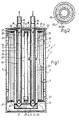
- Number 1 in Fig. 1 indicates a fluid purifying- sterilizing device, even for fluids impervious to ultraviolet rays, comprising an outer casing 2 preferably formed from metal and in the form of a rectangular parallelepipedon.
- the said casing 2 comprises a top wall 3, a bottom wall 4, a first pair of parallel side walls 5, and a second pair of parallel side walls 6 (only one of which is shown) perpendicular to walls 5.
- a duct 8 for the said unsterilized fluid which duct 8 may be of any shape, but, in the example shown, is substantially U-shaped with its concave side facing upwards.
- the said duct 8 comprises a downward duct 10 and an upward duct 11 parallel with each other, formed from unwettable material transparent to ultraviolet rays, and connected at their respective bottom ends by a horizontal duct 12.
- the top ends of ducts 10 and 11 are engaged inside respective tubular ends of an outlet pipe 13 and inlet pipe 14 respectively, which pipes 13 and 14 extend through respective holes 15 and 16 formed through wall 3, and are connected to the said wall 3 via respective flanges 17 and 18.
- Each of ducts 10 and 11 houses a tubular element 19 preferably formed from metal and closed at its opposite ends by plugs 20, each of which is secured to the inner surface of respective duct 10 or 11 by means of radial fins 21.
- the said tubular elements 19 extend along substantially the entire length of respective ducts 10 and 11 and define, with the same, respective toroidal passages 22 and- 23 along which the unsterilized fluid flows.
- lamps 24, 25, 26, are mounted inside the said chamber 7.
- Lamps 24 and 25 are connected by means of respective end brackets 27 to respective walls 5, in a position adjacent to ducts 10 and 11 respectively, and present respective reflecting paraboloids 28 for concentrating the emitted rays on to ducts 10 and 11.
- Lamp 26, on the other hand, is located midway between ducts 10 and 11, and is supported by end brackets 29 connected to one of walls 6.
- the unsterilized fluid is fed into inlet pipe 14 by a supply network (not shown) and flows along duct 8 by successively flowing along passage 23, duct 12 and passage 22, as far as outlet pipe 13.
- the unsterilized fluid assumes a swirling motion due to the fact that, as ducts 10 and 11 are formed from unwettable material, such as TEFLON@, the fluid particles substantially contacting the inner surfaces of ducts 10 and 11 encounter substantially no frictional resistance and, therefore, tend to travel faster than the other particles.
- the size of the vortices formed inside passages 22 and 23 remains substantially constant for a given flow rate.
- all the unsterilized fluid particles may be brought successively into contact with the inner surfaces of ducts 10 and 11, that is, into a position enabling the particles to be sterilized by a superficial bombardment of ultraviolet rays emitted by lamps 24, 25 and 26.
- duct 8 may consist of a coil, or be of any appropriate shape other than the one described herein.
- passages 22 and 23 may be flat, instead of toroidal as in the example shown.
- tubular elements 19 may be formed from material designed to reflect ultraviolet rays, or, they too, from unwettable material transparent to ultraviolet rays.
- the ultraviolet lamps employed may differ in number and/or be positioned differently from those described herein.
- device 1 as described herein may constitute only one sterilizing unit on a system comprising a number of such units connected in various ways and housed either in respective casings 2 or in a single common casing.
Landscapes
- Life Sciences & Earth Sciences (AREA)
- Engineering & Computer Science (AREA)
- Health & Medical Sciences (AREA)
- Chemical & Material Sciences (AREA)
- General Health & Medical Sciences (AREA)
- Public Health (AREA)
- Polymers & Plastics (AREA)
- Zoology (AREA)
- Epidemiology (AREA)
- Animal Behavior & Ethology (AREA)
- Wood Science & Technology (AREA)
- Food Science & Technology (AREA)
- Veterinary Medicine (AREA)
- Toxicology (AREA)
- Hydrology & Water Resources (AREA)
- Environmental & Geological Engineering (AREA)
- Water Supply & Treatment (AREA)
- Organic Chemistry (AREA)
- Apparatus For Disinfection Or Sterilisation (AREA)
- Physical Water Treatments (AREA)
Claims (4)
Applications Claiming Priority (2)
| Application Number | Priority Date | Filing Date | Title |
|---|---|---|---|
| IT6786386 | 1986-11-21 | ||
| IT67863/86A IT1195844B (it) | 1986-11-21 | 1986-11-21 | Metodo e dispositivo per la sterilizzazione di fluidi |
Publications (2)
| Publication Number | Publication Date |
|---|---|
| EP0268968A1 EP0268968A1 (fr) | 1988-06-01 |
| EP0268968B1 true EP0268968B1 (fr) | 1991-02-06 |
Family
ID=11305883
Family Applications (1)
| Application Number | Title | Priority Date | Filing Date |
|---|---|---|---|
| EP87116888A Expired EP0268968B1 (fr) | 1986-11-21 | 1987-11-16 | Procédé fluide de sterilisation et dispositif |
Country Status (5)
| Country | Link |
|---|---|
| EP (1) | EP0268968B1 (fr) |
| DE (1) | DE3767976D1 (fr) |
| ES (1) | ES2020249B3 (fr) |
| GR (1) | GR3001887T3 (fr) |
| IT (1) | IT1195844B (fr) |
Families Citing this family (3)
| Publication number | Priority date | Publication date | Assignee | Title |
|---|---|---|---|---|
| US4798702A (en) * | 1986-09-10 | 1989-01-17 | Tucker Robert E | Sterilizer unit for fluid media and process |
| IT1257212B (it) * | 1992-06-02 | 1996-01-10 | Metodo e dispositivo per la sterilizzazione di fluidi. | |
| US6015229A (en) | 1997-09-19 | 2000-01-18 | Calgon Carbon Corporation | Method and apparatus for improved mixing in fluids |
Family Cites Families (3)
| Publication number | Priority date | Publication date | Assignee | Title |
|---|---|---|---|---|
| DE885344C (de) * | 1942-12-10 | 1953-08-03 | Siemens Ag | Einrichtung zur Ultraviolettbestrahlung von Fluessigkeiten |
| US2586625A (en) * | 1948-06-08 | 1952-02-19 | Virgil M Downey | Apparatus for treating materials by ultraviolet radiation |
| US4534282A (en) * | 1982-05-04 | 1985-08-13 | Marinoza Rene A | Process and apparatus for treating food products |
-
1986
- 1986-11-21 IT IT67863/86A patent/IT1195844B/it active
-
1987
- 1987-11-16 ES ES87116888T patent/ES2020249B3/es not_active Expired - Lifetime
- 1987-11-16 EP EP87116888A patent/EP0268968B1/fr not_active Expired
- 1987-11-16 DE DE8787116888T patent/DE3767976D1/de not_active Expired - Fee Related
-
1991
- 1991-04-30 GR GR91400569T patent/GR3001887T3/el unknown
Also Published As
| Publication number | Publication date |
|---|---|
| GR3001887T3 (en) | 1992-11-23 |
| ES2020249B3 (es) | 1991-08-01 |
| IT8667863A1 (it) | 1988-05-21 |
| EP0268968A1 (fr) | 1988-06-01 |
| IT1195844B (it) | 1988-10-27 |
| DE3767976D1 (de) | 1991-03-14 |
| IT8667863A0 (it) | 1986-11-21 |
Similar Documents
| Publication | Publication Date | Title |
|---|---|---|
| US4968891A (en) | Disinfecting a fluid with ultraviolet radiation | |
| EP0269941A1 (fr) | Procédé fluide de sterilisation et dispositif | |
| CN104780945B (zh) | 具有高度均匀辐射场的紧凑系统 | |
| US5740315A (en) | Fluid heating apparatus | |
| CA2513878C (fr) | Dispositif modulaire pour desinfecter un grand volume de liquide sous haute pression a l'aide d'un rayonnement uv | |
| MX2012004726A (es) | Purificacion de agua. | |
| KR880701113A (ko) | 유체정제장치 | |
| CN102427830A (zh) | Uv液体灭菌器 | |
| EA006061B1 (ru) | Стерилизация жидкостей с использованием ультрафиолетового источника света | |
| JPS59150589A (ja) | 用廃水の浄化方法とその装置 | |
| EA000454B1 (ru) | Корпусной трубчатый теплообменник | |
| WO1983002241A1 (fr) | Dispositif de traitement des eaux | |
| EP0268968B1 (fr) | Procédé fluide de sterilisation et dispositif | |
| WO2003031338A2 (fr) | Appareil pour le traitement de l'eau | |
| JPS63302940A (ja) | 流体殺菌方法および装置 | |
| JPH0866677A (ja) | 紫外線殺菌蛇口 | |
| US6781137B2 (en) | Fluid treatment apparatus | |
| KR100618480B1 (ko) | 깊은 프라이어의 열교환기용 와류 챔버 | |
| JPS6063050A (ja) | 流体の殺菌装置 | |
| US6209536B1 (en) | Venturi apparatus for deep fryer | |
| WO2007082337A1 (fr) | Ameliorations liees aux appareils de traitement d'eau | |
| GB2596281A (en) | Dispensing apparatus | |
| CN117164058B (zh) | 一种可拆卸式过流式末端杀菌装置 | |
| EP4265123B1 (fr) | Unité de traitement uv | |
| SU969304A1 (ru) | Устройство дл контактировани газа и жидкости |
Legal Events
| Date | Code | Title | Description |
|---|---|---|---|
| PUAI | Public reference made under article 153(3) epc to a published international application that has entered the european phase |
Free format text: ORIGINAL CODE: 0009012 |
|
| AK | Designated contracting states |
Kind code of ref document: A1 Designated state(s): CH DE ES FR GB GR LI NL SE |
|
| 17P | Request for examination filed |
Effective date: 19881124 |
|
| 17Q | First examination report despatched |
Effective date: 19900327 |
|
| GRAA | (expected) grant |
Free format text: ORIGINAL CODE: 0009210 |
|
| AK | Designated contracting states |
Kind code of ref document: B1 Designated state(s): CH DE ES FR GB GR LI NL SE |
|
| REF | Corresponds to: |
Ref document number: 3767976 Country of ref document: DE Date of ref document: 19910314 |
|
| ET | Fr: translation filed | ||
| PLBE | No opposition filed within time limit |
Free format text: ORIGINAL CODE: 0009261 |
|
| STAA | Information on the status of an ep patent application or granted ep patent |
Free format text: STATUS: NO OPPOSITION FILED WITHIN TIME LIMIT |
|
| 26N | No opposition filed | ||
| REG | Reference to a national code |
Ref country code: GR Ref legal event code: FG4A Free format text: 3001887 |
|
| EAL | Se: european patent in force in sweden |
Ref document number: 87116888.6 |
|
| PGFP | Annual fee paid to national office [announced via postgrant information from national office to epo] |
Ref country code: GB Payment date: 19991105 Year of fee payment: 13 |
|
| PGFP | Annual fee paid to national office [announced via postgrant information from national office to epo] |
Ref country code: SE Payment date: 19991108 Year of fee payment: 13 |
|
| PGFP | Annual fee paid to national office [announced via postgrant information from national office to epo] |
Ref country code: FR Payment date: 19991110 Year of fee payment: 13 |
|
| PGFP | Annual fee paid to national office [announced via postgrant information from national office to epo] |
Ref country code: CH Payment date: 19991111 Year of fee payment: 13 |
|
| PGFP | Annual fee paid to national office [announced via postgrant information from national office to epo] |
Ref country code: ES Payment date: 19991116 Year of fee payment: 13 |
|
| PGFP | Annual fee paid to national office [announced via postgrant information from national office to epo] |
Ref country code: NL Payment date: 19991129 Year of fee payment: 13 |
|
| PGFP | Annual fee paid to national office [announced via postgrant information from national office to epo] |
Ref country code: GR Payment date: 19991130 Year of fee payment: 13 |
|
| PGFP | Annual fee paid to national office [announced via postgrant information from national office to epo] |
Ref country code: DE Payment date: 19991209 Year of fee payment: 13 |
|
| PG25 | Lapsed in a contracting state [announced via postgrant information from national office to epo] |
Ref country code: GB Free format text: LAPSE BECAUSE OF NON-PAYMENT OF DUE FEES Effective date: 20001116 |
|
| PG25 | Lapsed in a contracting state [announced via postgrant information from national office to epo] |
Ref country code: ES Free format text: LAPSE BECAUSE OF NON-PAYMENT OF DUE FEES Effective date: 20001117 |
|
| PG25 | Lapsed in a contracting state [announced via postgrant information from national office to epo] |
Ref country code: SE Free format text: THE PATENT HAS BEEN ANNULLED BY A DECISION OF A NATIONAL AUTHORITY Effective date: 20001129 |
|
| PG25 | Lapsed in a contracting state [announced via postgrant information from national office to epo] |
Ref country code: LI Free format text: LAPSE BECAUSE OF NON-PAYMENT OF DUE FEES Effective date: 20001130 Ref country code: GR Free format text: LAPSE BECAUSE OF NON-PAYMENT OF DUE FEES Effective date: 20001130 Ref country code: CH Free format text: LAPSE BECAUSE OF NON-PAYMENT OF DUE FEES Effective date: 20001130 |
|
| PG25 | Lapsed in a contracting state [announced via postgrant information from national office to epo] |
Ref country code: NL Free format text: LAPSE BECAUSE OF NON-PAYMENT OF DUE FEES Effective date: 20010601 |
|
| GBPC | Gb: european patent ceased through non-payment of renewal fee |
Effective date: 20001116 |
|
| REG | Reference to a national code |
Ref country code: CH Ref legal event code: PL |
|
| EUG | Se: european patent has lapsed |
Ref document number: 87116888.6 |
|
| PG25 | Lapsed in a contracting state [announced via postgrant information from national office to epo] |
Ref country code: FR Free format text: LAPSE BECAUSE OF NON-PAYMENT OF DUE FEES Effective date: 20010731 |
|
| NLV4 | Nl: lapsed or anulled due to non-payment of the annual fee |
Effective date: 20010601 |
|
| PG25 | Lapsed in a contracting state [announced via postgrant information from national office to epo] |
Ref country code: DE Free format text: LAPSE BECAUSE OF NON-PAYMENT OF DUE FEES Effective date: 20010801 |
|
| REG | Reference to a national code |
Ref country code: FR Ref legal event code: ST |
|
| REG | Reference to a national code |
Ref country code: ES Ref legal event code: FD2A Effective date: 20011214 |