EP0269110B1 - Übertragungsmethode einer Phosphorfolie - Google Patents
Übertragungsmethode einer Phosphorfolie Download PDFInfo
- Publication number
- EP0269110B1 EP0269110B1 EP87117494A EP87117494A EP0269110B1 EP 0269110 B1 EP0269110 B1 EP 0269110B1 EP 87117494 A EP87117494 A EP 87117494A EP 87117494 A EP87117494 A EP 87117494A EP 0269110 B1 EP0269110 B1 EP 0269110B1
- Authority
- EP
- European Patent Office
- Prior art keywords
- stimulable phosphor
- phosphor sheet
- sheet
- conveying
- driving members
- Prior art date
- Legal status (The legal status is an assumption and is not a legal conclusion. Google has not performed a legal analysis and makes no representation as to the accuracy of the status listed.)
- Expired - Lifetime
Links
Images
Classifications
-
- G—PHYSICS
- G21—NUCLEAR PHYSICS; NUCLEAR ENGINEERING
- G21K—HANDLING OF PARTICLES OR IONISING RADIATION NOT OTHERWISE PROVIDED FOR; IRRADIATION DEVICES; GAMMA RAY OR X-RAY MICROSCOPES
- G21K4/00—Conversion screens for the conversion of the spatial distribution of X-rays or particle radiation into visible images, e.g. fluoroscopic screens
Definitions
- the present invention relates to a method of conveying a stimulable phosphor sheet.
- a radiation image recording and reproducing method utilizing a stimulable phosphor as described, for instance, in US-A-4 239 968, has been developed and paid much attention.
- the method involves steps of causing a stimulable phosphor to absorb a radiation having passed through an object or having radiated from an object; sequentially exciting (or scanning) the phosphor with an electromagnetic wave such as visible light or infrared rays (stimulating rays) to release the radiation energy stored in the phosphor as light emission (stimulated emission); photoelectrically detecting the emitted light to obtain electric signals; and reproducing the radiation image of the object as a visible image, numerals, symbols, etc. from the electric signals.
- an electromagnetic wave such as visible light or infrared rays (stimulating rays)
- the radiation image recording and reproducing method a radiation image is obtainable with a sufficient amount of information by applying a radiation to the object at a considerably smaller dose, as compared with the conventional radiography. Accordingly, the radiation image recording and reproducing method is of great value, especially when the method is used for medical diagnosis.
- a stimulable phosphor is generally employed in the form of a stimulable phosphor sheet (also referred to as a radiation image storage panel, and generally in the form of a sheet of rectangle, square, etc.) which comprises a support and a phosphor layer provided thereon.
- the phosphor layer comprises a stimulable phosphor and a binder.
- a protective film made of a transparent plastic film is provided on a surface of the phosphor layer to protect the phosphor layer from physical and chemical deterioration.
- the stimulable phosphor sheet does not serve to finally record image information, but only stores the information temporarily to provide the image or the like or an independently prepared final recording medium as described above. Accordingly, the stimulable phosphor sheet can be repeatedly used and such repeated use brings about economical advantage.
- the repeated use of the stimulable phosphor sheet is particularly advantageous, for instance, in the case that a radiation image information recording and reading device employing the stimulable phosphor sheet is mounted on a traveling station such as a radiographic apparatus-carryig car to conduct mass radiographic examination in various places. More in detail, it is inconvenient to carry a great number of stimulable phosphor sheets on a traveling station, and there is a limitation on the number of sheets capable of being carried on a car such as a radiographic apparatus-carrying car.
- the stimulable phosphor sheets are mounted on a radiographic car under such conditions that the stimulable phosphor sheets are repeatedly used; radiation image information of an object is recorded on each stimulable phosphor sheet and read out to obtain image information as a signal; and the obtained signal is transferred to a recording medium having a great recording capacity such as a magnetic tape so as to repeatedly use the stimulable phosphor sheet in cycle.
- a recording medium having a great recording capacity such as a magnetic tape
- the stimulable phosphor sheet In the case of performing repeated uses of the stimulable phosphor sheets in cycle, after the radiation energy stored in the stimulable phosphor sheet is read out and aimed image information is obtained, the remaining energy in the sheet is released and erased in a manner as disclosed, for instance, in JP-A-56-11392 and JP-A-56-12599. By employing such manner, the stimulable phosphor sheet can be efficiently and repeatedly used in cycle.
- the radiation image information recording and reading device in one aspect, is desirably mounted on a traveling station such as a radiographic apparatus-carrying car in the form of a united built-in device which comprises an image recording means for exposing a stimulable phosphor sheet to a radiation having passed through an object so as to record and store a radiation image in the stimulable phosphor sheet, a read-out means for reading out the radiation image stored in the stimulable phosphor sheet, an erasure means for releasing and erasing radiation energy remaining in the stimulable phosphor sheet for the next use of the stimulable phosphor sheet, and a conveyance means for moving the stimulable phosphor sheet in cycle to each of the above-mentioned means.
- the radiation image information recording and reading device having the above-mentioned constitution have various advantages not only in mounting in the traveling station such as a radiographic apparatus-carrying car but also in setting in hospitals, so that the above device is convenient in practical use.
- the radiation image information recording and reading device utilizing the above-mentioned system of repeatedly and cyclically using the stimulable phosphor sheet is disclosed in JP-A-58-66730.
- the stimulable phosphor sheet is occasionally conveyed vertically or almost vertically for the purpose of making the device compact.
- a stimulable phosphor sheet has physical deterioration such as a scratch on a surface thereof (a phosphor layer-side surface of the sheet), the quality of image or the accuracy of image information provided by the phosphor sheet tends to decrease markedly. For this reason, it is necessary to select the means for conveying a stimulable phosphor sheet with such a careful consideration that the surface of the stimulable phosphor sheet is not damaged. From this viewpoint, as a means for conveying a stimulable phosphor sheet, a belt conveyor made of a soft sheet-material is generally employed.
- the belt conveyor is suitable for conveying the stimulable phosphor sheet horizontally, it is unsuitable for conveying the stimulable phosphor sheet in the direction other than the horizontal direction, particularly in the vertical or almost vertical direction. More in detail, in the process for conveying a stimulable phosphor sheet vertically or almost vertically using a belt conveyor, it is necessary to arrange a pair of belt conveyors in such a manner that the belt conveyors are in face to face contact with each other so as to convey the stimulable phosphor sheet under the condition that the stimulable phosphor sheet is sandwiched between that pair of belt conveyors.
- said conveying device is complicated in structure, and it is difficult to make the device compact. Further, there are other problems such that the surface of the stimulable phosphor sheet tends to suffer scratches when the rate of one belt conveyor is made different from that of the other, even if the difference therebetween is very small.
- a method of conveying a sheet in accordance with the preamble of claim 1 is known from EP-A-0 034 269.
- This document discloses a recirculating document feeder for a copying machine, by which the document is moved in a horizontal direction relative to a document glass. If more than one copy is to be made, the document is circulated by means of a curved guide plate. The document is moved upwardly by a horizontally applied driving power of a couple of rollers in combination with the curved inner surface of the guide plate. Accordingly, the surface of the document is continuously and repeatedly wrapped by the edge and the inner surface of the guide plate. This provides no problems, as far as paper documents are concerned, because such small scratches do not cause any harmful effect to the documents. If however, a stimulable phosphor sheet having a relatively harder phosphor layer is moved upwardly by such a device, the surface of that phosphor sheet will be destroyed by those scratches.
- the present invention provides a method suitable for conveying a stimulable phosphor sheet, particularly suitable for conveying a stimulable phosphor sheet in the vertical or almost vertical direction which is highly required in the radiation image information recording and reading device in which the stimulable phosphor sheet is repeatedly used in cycle.
- the general constitution of the conventional stimulable phosphor sheet which is an object of the conveyance in the present invention is well known.
- the stimulable phosphor sheet is generally employed, as described above, in the form of a sheet comprising a support and a phosphor layer provided thereon which comprises a stimulable phosphor and a binder.
- a protective film of a transparent plastic material On the surface of the phosphor layer is provided a protective film of a transparent plastic material, because the phosphor layer is easily affected by physical shocks.
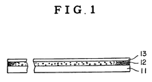
- Fig. 1 schematically illustrates the constitution of the conventional stimulable phosphor sheet.
- the stimulable phosphor sheet comprises a support 11, a phosphor layer 12 and a protective film 13.
- the support material include plastic films such as films of cellulose acetate and polyethylene terephthalate, metal sheets such as aluminum foil, ordinary papers, baryta paper, and resin-coated papers.
- On the surface of the support may be provided other functional layers such as an adhesive layer, a light-reflecting layer and a light-absorbing layer.
- the phosphor layer essentially comprises stimulable phosphor particles dispersed in a binder.
- the stimulable phosphor employed in the invention can be selected from the known stimulable phosphors.
- Examples of the known stimulable phosphor include a divalent europium activated alkaline earth metal fluorohalide phosphor (M II FX:Eu2+, 6in which M II is at least one alkaline earth metal selected from the group consisting of Mg, Ca and Ba; and X is at least one halogen selected from the group consisting of Cl, Br, and I); an europium and samarium activated strontium sulfide phosphor (SrS:Eu,Sm); an europium and samarium activated lanthanum oxysulfide phosphor (La2O2S:Eu,Sm); an europium activated barium aluminate phosphor (BaO ⁇ Al2O3:Eu
- a transparent protective film is then provided on the surface of the phosphor layer to physically and chemically protect the phosphor layer.
- the material employable for the preparation of the transparent protective film include cellulose acetate, polymethyl methacrylate, polyethylene terephthalate and polyethylene.
- the transparent protective film generally has a thickness within the range of approx. 0.1 - 20 »m.
- the stimulable phosphor sheet can be colored with an appropriate colorant as described in US-A-4 394 581. Further, white powder may be dispersed in the phosphor layer as described in US-A-4 350 893.
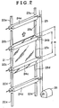
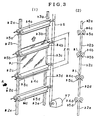
- FIGs. 2 and 3 [(1) and (2)] are schematic views of the conveying device which are preferably employed in the method of conveying a stimulable phosphor sheet according to the present invention.
- the method of conveying a stimulable phosphor sheet of the invention is described hereinafter, by referring to an embodiment employing the conveying devices shown in Figs. 2 and 3.
- the conveying device preferably employed in the method of conveying a stimulable phosphor sheet according to the invention is a device basically comprising guiding members 22 and 23 (22a, 23a, 22b, 23b, ...)[32 and 33 (32a, 33a, 32b, 33b, ...)[ for keeping both sides of a stimulable phosphor sheet 21[31], and two or more driving members 24 (24a, 24b, 24c, ...)[34 (34a, 34b, 34c, ...)] arranged along the conveying direction (direction along the indicated arrow) for providing a driving force on both surfaces of the stimulable phosphor sheet 21[31], in which the distance between said two driving members which adjoin each other along the conveying direction (e.g., 24b and 24c)[e.g., 34b and 34c] is smaller than the length of the stimulable phosphor sheet measured in the conveying direction.
- the guiding members of the device keep the stimulable phosphor sheet at the both sides thereof.
- the guiding members prevent the sheet from bending in the vertical direction against the surface plane of the sheet (namely, flexure) and from moving laterally.
- the guiding member is, for instance, U-shaped in the section. Accordingly, the guiding member is not necessarily in contact with the stimulable phosphor sheet to keep it.
- the surface of the sheet on which the radiation image is stored and recorded is kept being from contact with members of the device, since the stimulable phosphor sheet 21 is kept by the guiding members 22 and 23[32 and 33] at both sides of the sheet which do not participate in storing and recording the radiation image.
- the shape of the guiding member is not restricted to one as shown in Figs. 2 and 3, and any shape can be optionally used, as far as the guiding member has the above-described functions. Further, there is no specific limitation on the material of the guiding member.
- the guiding member is not necessarily employed in the form of individually separated member as shown in Figs. 2 and 3, and a united guiding member, for instance, a member in which one guiding member 22[32] is combined with another guiding member 23[33] on the back surface-side of the stimulable phosphor sheet 21[31] (support side-surface of the sheet) in Figs. 2 and 3, can be employed with appropriate selection of the driving members as described hereinafter.
- the driving members of the conveying device apply a driving force to the surface(s) of the stimulable phosphor sheet, and make it possible to convey (i.e., move) the stimulable phosphor sheet in a given direction.
- the driving members comprises at least two members, and the distance (l) between the two driving members which are adjacent to each other along the conveying direction is smaller than the length (m) of the stimulable phosphor sheet in the conveying direction. Two or more driving members having the above-described constitution can convey the stimulable phosphor sheet with little error.
- the driving member for providing a driving force on the surfaces of the stimulable phosphor sheet are a driving member comprising a pair of rollers as shown in Figs. 2 and 3.
- the length of the roller is preferably as almost the same as width of the stimulable phosphor sheet (length measured in the lateral direction, but the length of the roller is not restricted to the above-mentioned length.
- the roller may comprise a plurality of short rollers.
- the driving member may not consist a pair of rollers, and for example, a driving member comprising a driving roller and a fixed supporting member which is associated with the roller is employable. Further, other driving members than the above-mentioned rollers can be employed in the invention.
- the surface of the driving member especially the surface thereof which are to be in contact with the surface of the stimulable phosphor sheet, are preferably formed by a soft and elastic material such as rubber.
- a driving member having a surface of such material By employing a driving member having a surface of such material, the surface of the stimulable phosphor sheet can be protected from physical shock so as not to be damaged.
- the driving force is generally supplied to the driving members 24 (24a, 24b, 24c, ...)[24 (34a, 34b, 34c, ...)] from a means 26[37] such as a motor through a driving power-transmitting means 25[36] such as a chain and a belt. This driving force is then supplied to the stimulable phosphor sheet 21[31] under rotation via surfaces thereof.
- the guiding member and driving members are supported by an appropriate means such as a fixing means or a supporting means so as to fulfill each function in the area.
- the stimulable phosphor sheet can be easily and reliably conveyed in directions other that horizontal direction, particularly in the vertical or almost vertical direction, (upward and/or downward conveying), without damaging the surfaces of the sheet.
- the vertical or almost vertical conveyance giving no damage to the surface of stimulable phosphor sheet has been hardly attained in the conventional method using a belt conveyor.
- the method of conveying the stimulable phosphor sheet of the invention can be effectively used not only in the conveyance of a stimulable phosphor sheet in the vertical or almost vertical direction but also in the conveyance with alteration of the direction (e.g. L-turn and U-turn).
- the method of the invention can be effectively employed in the conveyance of a stimulable phosphor sheet in the horizontal direction.
- a belt conveyor is conventionally used in the conveyance thereof in such direction.
- the method of the present invention can be employed in combination with a conventional method using a belt conveyor in conveying the stimulable phosphor sheet in a radiation image information recording and reading device.
- the device illustrated in the Fig. 3 is further provided with a guiding means 35 (35a, 35b, 35c, ...) for guiding the front end of the stimulable phosphor sheet.
- the guiding means 35 is arranged in the vicinity of the driving means 24, for instance, just in front of the driving means 34.
- the guiding means 35 serves to smoothly engage the coming stimulable phosphor sheet with the driving means.
- the stimulable phosphor sheet essentially comprising a support and a phosphor layer is considerably rigid, flexure may occasionally happen on most of the conventional stimulable phosphor sheet used in a relatively thin plate having a width of approx. 30 - 60 cm at the front end.
- the guiding means 35 for guiding the front end of the stimulable phosphor sheet is very effective to enable smooth engagement between the stimulable phosphor sheet and the driving means.
- the front end-guiding means can be in the form of a roller arranged in the vicinity of the driving means.
- the front end-guiding means can be arranged merely on one side of the conveyor.
- the front end-guiding means is generally made of plastic material and metal.
- the method of the invention is suitable for conveying a stimulable phosphor sheet in the vertical or almost vertical direction. Accordingly, from the viewpoint of making the device compact, the method of the invention can be preferably and practically employed in the radiation image information recording and reading device in which the stimulable phosphor sheet is required to be conveyed in such direction so as to be repeatedly used in cycle.
Landscapes
- Physics & Mathematics (AREA)
- Engineering & Computer Science (AREA)
- General Engineering & Computer Science (AREA)
- High Energy & Nuclear Physics (AREA)
- Conversion Of X-Rays Into Visible Images (AREA)
- Radiography Using Non-Light Waves (AREA)
Claims (5)
- Ein Verfahren zum Fördern eines anregbaren, flächigen Leuchtstoffelements bzw. -folie, umfassend Anwenden einer Antriebskraft auf eine Oberfläche des anregbaren, flächigen Leuchtstoffelements (21, 31) mittels einer Vielzahl von Antriebselementen (24, 34) in der Form von drehbaren Walzen, wobei die Drehachse der Antriebselemente in einer im wesentlichen horizontalen Richtung angeordnet ist, und wobei der Abstand zwischen zwei Antriebselementen (24, 34), die einander entlang der vertikalen Richtung folgen, kleiner als die Länge des genannten anregbaren, flächigen Leuchtstoffelements ist, und Führen der Seitenkanten des genannten anregbaren, flächigen Leuchtstoffelements durch Führungselemente, dadurch gekennzeichnet, daß die genannten Antriebselemente (24, 34) drehbare Walzen sind, die in Paaren angeordnet sind, um das anregbare, flächige Leuchtstoffelement in einer im wesentlichen vertikalen Richtung zu fördern, daß das flächige Element (24, 31) zwischen dem genannten Paar Antriebselemente in Eingriff zu bringen ist, daß wenigstens ein Element (24, 34a) von jedem Paar von Führungselementen U-förmig ist und einen Abstand voneinander von wenigstens der Querabmessung des flächigen Elements (22, 31) zum Führen beider Ränder des genannten flächigen Elements aufweisen.
- Das Verfahren des Anspruchs 1, dadurch gekennzeichnet, daß das genannte anregbare, flächige Leuchtstoffelement (31) glatt zwischen dem genannten Paar von Antriebselementen (24, 34) durch eine Führungseinrichtung (35) in Eingriff gebracht wird, die in der Nähe der genannten Antriebselemente (24, 34) angeordnet ist.
- Das Verfahren des Anspruchs 1, dadurch gekennzeichnet, daß das genannte anregbare, flächige Leuchtstoffelement (31) aufwärts gefördert wird, wobei wenigstens drei Paare von Antriebselementen (24, 34) verwendet werden.
- Das Verfahren des Anspruchs 1, dadurch gekennzeichnet, daß jedes der genannten Antriebselemente (24, 34) eine drehbare Walze ist, die eine lange Länge aufweist, daß die genannte Länge im wesentlichen die gleiche wie die Länge der Querrichtung (d.h. die seitliche Länge) des anregbaren, flächigen Leuchtstoffelements ist.
- Das Verfahren des Anspruchs 1, dadurch gekennzeichnet, daß jedes der Antriebselemente (24, 34) von jedem Paar im wesentlichen den gleichen Durchmesser hat.
Applications Claiming Priority (15)
| Application Number | Priority Date | Filing Date | Title |
|---|---|---|---|
| JP69587/84 | 1984-04-06 | ||
| JP69583/84 | 1984-04-06 | ||
| JP6958584A JPS60211398A (ja) | 1984-04-06 | 1984-04-06 | 蓄積性蛍光体シートの搬送方法 |
| JP6958684A JPS60211399A (ja) | 1984-04-06 | 1984-04-06 | 蓄積性蛍光体シートの搬送方法 |
| JP6958784A JPS60211400A (ja) | 1984-04-06 | 1984-04-06 | 蓄積性蛍光体シ−トとその搬送方法 |
| JP69584/84 | 1984-04-06 | ||
| JP6958884A JPS60213897A (ja) | 1984-04-06 | 1984-04-06 | 蓄積性蛍光体シ−トとその搬送方法 |
| JP69588/84 | 1984-04-06 | ||
| JP69585/84 | 1984-04-06 | ||
| JP6958384A JPS60213646A (ja) | 1984-04-06 | 1984-04-06 | 蓄積性蛍光体シ−トの搬送方法および搬送装置 |
| JP69586/84 | 1984-04-06 | ||
| JP6958484A JPS60212754A (ja) | 1984-04-06 | 1984-04-06 | 蓄積性蛍光体シ−トの搬送方法 |
| JP180124/84 | 1984-08-29 | ||
| JP18012484A JPS6157941A (ja) | 1984-08-29 | 1984-08-29 | 蓄積性螢光体シ−トの搬送方法および搬送装置 |
| EP85104263A EP0159613B1 (de) | 1984-04-06 | 1985-04-09 | Vorrichtung zur Beförderung einer anregbaren Phosphorschicht |
Related Parent Applications (1)
| Application Number | Title | Priority Date | Filing Date |
|---|---|---|---|
| EP85104263.0 Division | 1985-04-09 |
Publications (3)
| Publication Number | Publication Date |
|---|---|
| EP0269110A2 EP0269110A2 (de) | 1988-06-01 |
| EP0269110A3 EP0269110A3 (en) | 1988-10-19 |
| EP0269110B1 true EP0269110B1 (de) | 1995-07-26 |
Family
ID=27570839
Family Applications (1)
| Application Number | Title | Priority Date | Filing Date |
|---|---|---|---|
| EP87117494A Expired - Lifetime EP0269110B1 (de) | 1984-04-06 | 1985-04-09 | Übertragungsmethode einer Phosphorfolie |
Country Status (1)
| Country | Link |
|---|---|
| EP (1) | EP0269110B1 (de) |
Family Cites Families (1)
| Publication number | Priority date | Publication date | Assignee | Title |
|---|---|---|---|---|
| JPH0685045B2 (ja) * | 1982-05-19 | 1994-10-26 | 富士写真フイルム株式会社 | 放射線画像情報変換方法および装置 |
-
1985
- 1985-04-09 EP EP87117494A patent/EP0269110B1/de not_active Expired - Lifetime
Also Published As
| Publication number | Publication date |
|---|---|
| EP0269110A2 (de) | 1988-06-01 |
| EP0269110A3 (en) | 1988-10-19 |
Similar Documents
| Publication | Publication Date | Title |
|---|---|---|
| US4543479A (en) | Radiation image recording and read-out system | |
| EP0158959B1 (de) | Anregbare Phosphorschicht | |
| US4665003A (en) | Stimulable phosphor sheet and method of conveying the same | |
| US4728798A (en) | Radiation image storage panel and process for the preparation of the same | |
| US5013916A (en) | Method and apparatus for recording and reading out radiation images | |
| EP0482676B1 (de) | Strahlungsbild-Speicherplatte und Verfahren zum Bewegen dieser Platte in einem Bildspeicher- und Auslesegerät | |
| EP0285702B1 (de) | Anregbare Phosphorfolie | |
| EP0269110B1 (de) | Übertragungsmethode einer Phosphorfolie | |
| JPH0131372B2 (de) | ||
| US4752687A (en) | Radiation image erase unit for use with stimulable pyhosphor sheet | |
| US6534779B1 (en) | Conveyance of stimulable phosphor sheet | |
| JPS60211398A (ja) | 蓄積性蛍光体シートの搬送方法 | |
| JPS60211399A (ja) | 蓄積性蛍光体シートの搬送方法 | |
| JPS6140600A (ja) | 蓄積性螢光体シ−トとその搬送方法 | |
| JPS6140599A (ja) | 蓄積性螢光体シ−トその搬送方法 | |
| JPH0434717B2 (de) | ||
| JPH0434716B2 (de) | ||
| JPS60213898A (ja) | 蓄積性蛍光体シ−ト | |
| JPH0554920B2 (de) | ||
| JPS60212754A (ja) | 蓄積性蛍光体シ−トの搬送方法 | |
| JP3981501B2 (ja) | 蓄積性蛍光体シートの搬送方法 | |
| JPS60213899A (ja) | 蓄積性蛍光体シ−ト | |
| JP3999392B2 (ja) | 蓄積性蛍光体シートの搬送装置および搬送方法 | |
| JPS6236597A (ja) | 放射線像変換パネル | |
| JPS60262100A (ja) | 放射線画像変換方法 |
Legal Events
| Date | Code | Title | Description |
|---|---|---|---|
| PUAI | Public reference made under article 153(3) epc to a published international application that has entered the european phase |
Free format text: ORIGINAL CODE: 0009012 |
|
| 17P | Request for examination filed |
Effective date: 19871126 |
|
| AC | Divisional application: reference to earlier application |
Ref document number: 159613 Country of ref document: EP |
|
| AK | Designated contracting states |
Kind code of ref document: A2 Designated state(s): BE DE FR GB NL |
|
| PUAL | Search report despatched |
Free format text: ORIGINAL CODE: 0009013 |
|
| AK | Designated contracting states |
Kind code of ref document: A3 Designated state(s): BE DE FR GB NL |
|
| 17Q | First examination report despatched |
Effective date: 19901220 |
|
| GRAA | (expected) grant |
Free format text: ORIGINAL CODE: 0009210 |
|
| AC | Divisional application: reference to earlier application |
Ref document number: 159613 Country of ref document: EP |
|
| AK | Designated contracting states |
Kind code of ref document: B1 Designated state(s): BE DE FR GB NL |
|
| REF | Corresponds to: |
Ref document number: 3588045 Country of ref document: DE Date of ref document: 19950831 |
|
| ET | Fr: translation filed | ||
| PLBE | No opposition filed within time limit |
Free format text: ORIGINAL CODE: 0009261 |
|
| STAA | Information on the status of an ep patent application or granted ep patent |
Free format text: STATUS: NO OPPOSITION FILED WITHIN TIME LIMIT |
|
| 26N | No opposition filed | ||
| REG | Reference to a national code |
Ref country code: GB Ref legal event code: IF02 |
|
| PGFP | Annual fee paid to national office [announced via postgrant information from national office to epo] |
Ref country code: GB Payment date: 20020325 Year of fee payment: 18 |
|
| PGFP | Annual fee paid to national office [announced via postgrant information from national office to epo] |
Ref country code: FR Payment date: 20020409 Year of fee payment: 18 |
|
| PGFP | Annual fee paid to national office [announced via postgrant information from national office to epo] |
Ref country code: NL Payment date: 20020430 Year of fee payment: 18 |
|
| PGFP | Annual fee paid to national office [announced via postgrant information from national office to epo] |
Ref country code: DE Payment date: 20020531 Year of fee payment: 18 |
|
| PGFP | Annual fee paid to national office [announced via postgrant information from national office to epo] |
Ref country code: BE Payment date: 20030214 Year of fee payment: 19 |
|
| PG25 | Lapsed in a contracting state [announced via postgrant information from national office to epo] |
Ref country code: GB Free format text: LAPSE BECAUSE OF NON-PAYMENT OF DUE FEES Effective date: 20030409 |
|
| PG25 | Lapsed in a contracting state [announced via postgrant information from national office to epo] |
Ref country code: NL Free format text: LAPSE BECAUSE OF NON-PAYMENT OF DUE FEES Effective date: 20031101 Ref country code: DE Free format text: LAPSE BECAUSE OF NON-PAYMENT OF DUE FEES Effective date: 20031101 |
|
| GBPC | Gb: european patent ceased through non-payment of renewal fee |
Effective date: 20030409 |
|
| NLV4 | Nl: lapsed or anulled due to non-payment of the annual fee |
Effective date: 20031101 |
|
| PG25 | Lapsed in a contracting state [announced via postgrant information from national office to epo] |
Ref country code: FR Free format text: LAPSE BECAUSE OF NON-PAYMENT OF DUE FEES Effective date: 20031231 |
|
| REG | Reference to a national code |
Ref country code: FR Ref legal event code: ST |
|
| PG25 | Lapsed in a contracting state [announced via postgrant information from national office to epo] |
Ref country code: BE Free format text: LAPSE BECAUSE OF NON-PAYMENT OF DUE FEES Effective date: 20040430 |
|
| BERE | Be: lapsed |
Owner name: *FUJI PHOTO FILM CO. LTD Effective date: 20040430 |