EP0269342A2 - Luftverflüssigung - Google Patents
Luftverflüssigung Download PDFInfo
- Publication number
- EP0269342A2 EP0269342A2 EP87310109A EP87310109A EP0269342A2 EP 0269342 A2 EP0269342 A2 EP 0269342A2 EP 87310109 A EP87310109 A EP 87310109A EP 87310109 A EP87310109 A EP 87310109A EP 0269342 A2 EP0269342 A2 EP 0269342A2
- Authority
- EP
- European Patent Office
- Prior art keywords
- column
- liquid
- oxygen
- outlet
- vapour
- Prior art date
- Legal status (The legal status is an assumption and is not a legal conclusion. Google has not performed a legal analysis and makes no representation as to the accuracy of the status listed.)
- Granted
Links
Images

Classifications
-
- F—MECHANICAL ENGINEERING; LIGHTING; HEATING; WEAPONS; BLASTING
- F25—REFRIGERATION OR COOLING; COMBINED HEATING AND REFRIGERATION SYSTEMS; HEAT PUMP SYSTEMS; MANUFACTURE OR STORAGE OF ICE; LIQUEFACTION SOLIDIFICATION OF GASES
- F25J—LIQUEFACTION, SOLIDIFICATION OR SEPARATION OF GASES OR GASEOUS OR LIQUEFIED GASEOUS MIXTURES BY PRESSURE AND COLD TREATMENT OR BY BRINGING THEM INTO THE SUPERCRITICAL STATE
- F25J3/00—Processes or apparatus for separating the constituents of gaseous or liquefied gaseous mixtures involving the use of liquefaction or solidification
- F25J3/02—Processes or apparatus for separating the constituents of gaseous or liquefied gaseous mixtures involving the use of liquefaction or solidification by rectification, i.e. by continuous interchange of heat and material between a vapour stream and a liquid stream
- F25J3/04—Processes or apparatus for separating the constituents of gaseous or liquefied gaseous mixtures involving the use of liquefaction or solidification by rectification, i.e. by continuous interchange of heat and material between a vapour stream and a liquid stream for air
- F25J3/04642—Recovering noble gases from air
- F25J3/04648—Recovering noble gases from air argon
- F25J3/04654—Producing crude argon in a crude argon column
- F25J3/04666—Producing crude argon in a crude argon column as a parallel working rectification column of the low pressure column in a dual pressure main column system
- F25J3/04672—Producing crude argon in a crude argon column as a parallel working rectification column of the low pressure column in a dual pressure main column system having a top condenser
- F25J3/04678—Producing crude argon in a crude argon column as a parallel working rectification column of the low pressure column in a dual pressure main column system having a top condenser cooled by oxygen enriched liquid from high pressure column bottoms
-
- F—MECHANICAL ENGINEERING; LIGHTING; HEATING; WEAPONS; BLASTING
- F25—REFRIGERATION OR COOLING; COMBINED HEATING AND REFRIGERATION SYSTEMS; HEAT PUMP SYSTEMS; MANUFACTURE OR STORAGE OF ICE; LIQUEFACTION SOLIDIFICATION OF GASES
- F25J—LIQUEFACTION, SOLIDIFICATION OR SEPARATION OF GASES OR GASEOUS OR LIQUEFIED GASEOUS MIXTURES BY PRESSURE AND COLD TREATMENT OR BY BRINGING THEM INTO THE SUPERCRITICAL STATE
- F25J3/00—Processes or apparatus for separating the constituents of gaseous or liquefied gaseous mixtures involving the use of liquefaction or solidification
- F25J3/02—Processes or apparatus for separating the constituents of gaseous or liquefied gaseous mixtures involving the use of liquefaction or solidification by rectification, i.e. by continuous interchange of heat and material between a vapour stream and a liquid stream
- F25J3/04—Processes or apparatus for separating the constituents of gaseous or liquefied gaseous mixtures involving the use of liquefaction or solidification by rectification, i.e. by continuous interchange of heat and material between a vapour stream and a liquid stream for air
- F25J3/04006—Providing pressurised feed air or process streams within or from the air fractionation unit
- F25J3/04078—Providing pressurised feed air or process streams within or from the air fractionation unit providing pressurized products by liquid compression and vaporisation with cold recovery, i.e. so-called internal compression
- F25J3/0409—Providing pressurised feed air or process streams within or from the air fractionation unit providing pressurized products by liquid compression and vaporisation with cold recovery, i.e. so-called internal compression of oxygen
-
- F—MECHANICAL ENGINEERING; LIGHTING; HEATING; WEAPONS; BLASTING
- F25—REFRIGERATION OR COOLING; COMBINED HEATING AND REFRIGERATION SYSTEMS; HEAT PUMP SYSTEMS; MANUFACTURE OR STORAGE OF ICE; LIQUEFACTION SOLIDIFICATION OF GASES
- F25J—LIQUEFACTION, SOLIDIFICATION OR SEPARATION OF GASES OR GASEOUS OR LIQUEFIED GASEOUS MIXTURES BY PRESSURE AND COLD TREATMENT OR BY BRINGING THEM INTO THE SUPERCRITICAL STATE
- F25J3/00—Processes or apparatus for separating the constituents of gaseous or liquefied gaseous mixtures involving the use of liquefaction or solidification
- F25J3/02—Processes or apparatus for separating the constituents of gaseous or liquefied gaseous mixtures involving the use of liquefaction or solidification by rectification, i.e. by continuous interchange of heat and material between a vapour stream and a liquid stream
- F25J3/04—Processes or apparatus for separating the constituents of gaseous or liquefied gaseous mixtures involving the use of liquefaction or solidification by rectification, i.e. by continuous interchange of heat and material between a vapour stream and a liquid stream for air
- F25J3/04151—Purification and (pre-)cooling of the feed air; recuperative heat-exchange with product streams
- F25J3/04187—Cooling of the purified feed air by recuperative heat-exchange; Heat-exchange with product streams
- F25J3/04193—Division of the main heat exchange line in consecutive sections having different functions
-
- F—MECHANICAL ENGINEERING; LIGHTING; HEATING; WEAPONS; BLASTING
- F25—REFRIGERATION OR COOLING; COMBINED HEATING AND REFRIGERATION SYSTEMS; HEAT PUMP SYSTEMS; MANUFACTURE OR STORAGE OF ICE; LIQUEFACTION SOLIDIFICATION OF GASES
- F25J—LIQUEFACTION, SOLIDIFICATION OR SEPARATION OF GASES OR GASEOUS OR LIQUEFIED GASEOUS MIXTURES BY PRESSURE AND COLD TREATMENT OR BY BRINGING THEM INTO THE SUPERCRITICAL STATE
- F25J3/00—Processes or apparatus for separating the constituents of gaseous or liquefied gaseous mixtures involving the use of liquefaction or solidification
- F25J3/02—Processes or apparatus for separating the constituents of gaseous or liquefied gaseous mixtures involving the use of liquefaction or solidification by rectification, i.e. by continuous interchange of heat and material between a vapour stream and a liquid stream
- F25J3/04—Processes or apparatus for separating the constituents of gaseous or liquefied gaseous mixtures involving the use of liquefaction or solidification by rectification, i.e. by continuous interchange of heat and material between a vapour stream and a liquid stream for air
- F25J3/04248—Generation of cold for compensating heat leaks or liquid production, e.g. by Joule-Thompson expansion
- F25J3/04284—Generation of cold for compensating heat leaks or liquid production, e.g. by Joule-Thompson expansion using internal refrigeration by open-loop gas work expansion, e.g. of intermediate or oxygen enriched (waste-)streams
- F25J3/0429—Generation of cold for compensating heat leaks or liquid production, e.g. by Joule-Thompson expansion using internal refrigeration by open-loop gas work expansion, e.g. of intermediate or oxygen enriched (waste-)streams of feed air, e.g. used as waste or product air or expanded into an auxiliary column
-
- F—MECHANICAL ENGINEERING; LIGHTING; HEATING; WEAPONS; BLASTING
- F25—REFRIGERATION OR COOLING; COMBINED HEATING AND REFRIGERATION SYSTEMS; HEAT PUMP SYSTEMS; MANUFACTURE OR STORAGE OF ICE; LIQUEFACTION SOLIDIFICATION OF GASES
- F25J—LIQUEFACTION, SOLIDIFICATION OR SEPARATION OF GASES OR GASEOUS OR LIQUEFIED GASEOUS MIXTURES BY PRESSURE AND COLD TREATMENT OR BY BRINGING THEM INTO THE SUPERCRITICAL STATE
- F25J3/00—Processes or apparatus for separating the constituents of gaseous or liquefied gaseous mixtures involving the use of liquefaction or solidification
- F25J3/02—Processes or apparatus for separating the constituents of gaseous or liquefied gaseous mixtures involving the use of liquefaction or solidification by rectification, i.e. by continuous interchange of heat and material between a vapour stream and a liquid stream
- F25J3/04—Processes or apparatus for separating the constituents of gaseous or liquefied gaseous mixtures involving the use of liquefaction or solidification by rectification, i.e. by continuous interchange of heat and material between a vapour stream and a liquid stream for air
- F25J3/04248—Generation of cold for compensating heat leaks or liquid production, e.g. by Joule-Thompson expansion
- F25J3/04375—Details relating to the work expansion, e.g. process parameter etc.
- F25J3/04393—Details relating to the work expansion, e.g. process parameter etc. using multiple or multistage gas work expansion
-
- F—MECHANICAL ENGINEERING; LIGHTING; HEATING; WEAPONS; BLASTING
- F25—REFRIGERATION OR COOLING; COMBINED HEATING AND REFRIGERATION SYSTEMS; HEAT PUMP SYSTEMS; MANUFACTURE OR STORAGE OF ICE; LIQUEFACTION SOLIDIFICATION OF GASES
- F25J—LIQUEFACTION, SOLIDIFICATION OR SEPARATION OF GASES OR GASEOUS OR LIQUEFIED GASEOUS MIXTURES BY PRESSURE AND COLD TREATMENT OR BY BRINGING THEM INTO THE SUPERCRITICAL STATE
- F25J3/00—Processes or apparatus for separating the constituents of gaseous or liquefied gaseous mixtures involving the use of liquefaction or solidification
- F25J3/02—Processes or apparatus for separating the constituents of gaseous or liquefied gaseous mixtures involving the use of liquefaction or solidification by rectification, i.e. by continuous interchange of heat and material between a vapour stream and a liquid stream
- F25J3/04—Processes or apparatus for separating the constituents of gaseous or liquefied gaseous mixtures involving the use of liquefaction or solidification by rectification, i.e. by continuous interchange of heat and material between a vapour stream and a liquid stream for air
- F25J3/04406—Processes or apparatus for separating the constituents of gaseous or liquefied gaseous mixtures involving the use of liquefaction or solidification by rectification, i.e. by continuous interchange of heat and material between a vapour stream and a liquid stream for air using a dual pressure main column system
- F25J3/04412—Processes or apparatus for separating the constituents of gaseous or liquefied gaseous mixtures involving the use of liquefaction or solidification by rectification, i.e. by continuous interchange of heat and material between a vapour stream and a liquid stream for air using a dual pressure main column system in a classical double column flowsheet, i.e. with thermal coupling by a main reboiler-condenser in the bottom of low pressure respectively top of high pressure column
-
- F—MECHANICAL ENGINEERING; LIGHTING; HEATING; WEAPONS; BLASTING
- F25—REFRIGERATION OR COOLING; COMBINED HEATING AND REFRIGERATION SYSTEMS; HEAT PUMP SYSTEMS; MANUFACTURE OR STORAGE OF ICE; LIQUEFACTION SOLIDIFICATION OF GASES
- F25J—LIQUEFACTION, SOLIDIFICATION OR SEPARATION OF GASES OR GASEOUS OR LIQUEFIED GASEOUS MIXTURES BY PRESSURE AND COLD TREATMENT OR BY BRINGING THEM INTO THE SUPERCRITICAL STATE
- F25J3/00—Processes or apparatus for separating the constituents of gaseous or liquefied gaseous mixtures involving the use of liquefaction or solidification
- F25J3/02—Processes or apparatus for separating the constituents of gaseous or liquefied gaseous mixtures involving the use of liquefaction or solidification by rectification, i.e. by continuous interchange of heat and material between a vapour stream and a liquid stream
- F25J3/04—Processes or apparatus for separating the constituents of gaseous or liquefied gaseous mixtures involving the use of liquefaction or solidification by rectification, i.e. by continuous interchange of heat and material between a vapour stream and a liquid stream for air
- F25J3/0446—Processes or apparatus for separating the constituents of gaseous or liquefied gaseous mixtures involving the use of liquefaction or solidification by rectification, i.e. by continuous interchange of heat and material between a vapour stream and a liquid stream for air using the heat generated by mixing two different phases
-
- F—MECHANICAL ENGINEERING; LIGHTING; HEATING; WEAPONS; BLASTING
- F25—REFRIGERATION OR COOLING; COMBINED HEATING AND REFRIGERATION SYSTEMS; HEAT PUMP SYSTEMS; MANUFACTURE OR STORAGE OF ICE; LIQUEFACTION SOLIDIFICATION OF GASES
- F25J—LIQUEFACTION, SOLIDIFICATION OR SEPARATION OF GASES OR GASEOUS OR LIQUEFIED GASEOUS MIXTURES BY PRESSURE AND COLD TREATMENT OR BY BRINGING THEM INTO THE SUPERCRITICAL STATE
- F25J3/00—Processes or apparatus for separating the constituents of gaseous or liquefied gaseous mixtures involving the use of liquefaction or solidification
- F25J3/02—Processes or apparatus for separating the constituents of gaseous or liquefied gaseous mixtures involving the use of liquefaction or solidification by rectification, i.e. by continuous interchange of heat and material between a vapour stream and a liquid stream
- F25J3/04—Processes or apparatus for separating the constituents of gaseous or liquefied gaseous mixtures involving the use of liquefaction or solidification by rectification, i.e. by continuous interchange of heat and material between a vapour stream and a liquid stream for air
- F25J3/04763—Start-up or control of the process; Details of the apparatus used
- F25J3/04769—Operation, control and regulation of the process; Instrumentation within the process
- F25J3/04812—Different modes, i.e. "runs" of operation
-
- F—MECHANICAL ENGINEERING; LIGHTING; HEATING; WEAPONS; BLASTING
- F25—REFRIGERATION OR COOLING; COMBINED HEATING AND REFRIGERATION SYSTEMS; HEAT PUMP SYSTEMS; MANUFACTURE OR STORAGE OF ICE; LIQUEFACTION SOLIDIFICATION OF GASES
- F25J—LIQUEFACTION, SOLIDIFICATION OR SEPARATION OF GASES OR GASEOUS OR LIQUEFIED GASEOUS MIXTURES BY PRESSURE AND COLD TREATMENT OR BY BRINGING THEM INTO THE SUPERCRITICAL STATE
- F25J2200/00—Processes or apparatus using separation by rectification
- F25J2200/04—Processes or apparatus using separation by rectification in a dual pressure main column system
- F25J2200/06—Processes or apparatus using separation by rectification in a dual pressure main column system in a classical double column flow-sheet, i.e. with thermal coupling by a main reboiler-condenser in the bottom of low pressure respectively top of high pressure column
-
- F—MECHANICAL ENGINEERING; LIGHTING; HEATING; WEAPONS; BLASTING
- F25—REFRIGERATION OR COOLING; COMBINED HEATING AND REFRIGERATION SYSTEMS; HEAT PUMP SYSTEMS; MANUFACTURE OR STORAGE OF ICE; LIQUEFACTION SOLIDIFICATION OF GASES
- F25J—LIQUEFACTION, SOLIDIFICATION OR SEPARATION OF GASES OR GASEOUS OR LIQUEFIED GASEOUS MIXTURES BY PRESSURE AND COLD TREATMENT OR BY BRINGING THEM INTO THE SUPERCRITICAL STATE
- F25J2200/00—Processes or apparatus using separation by rectification
- F25J2200/50—Processes or apparatus using separation by rectification using multiple (re-)boiler-condensers at different heights of the column
- F25J2200/52—Processes or apparatus using separation by rectification using multiple (re-)boiler-condensers at different heights of the column in the high pressure column of a double pressure main column system
-
- F—MECHANICAL ENGINEERING; LIGHTING; HEATING; WEAPONS; BLASTING
- F25—REFRIGERATION OR COOLING; COMBINED HEATING AND REFRIGERATION SYSTEMS; HEAT PUMP SYSTEMS; MANUFACTURE OR STORAGE OF ICE; LIQUEFACTION SOLIDIFICATION OF GASES
- F25J—LIQUEFACTION, SOLIDIFICATION OR SEPARATION OF GASES OR GASEOUS OR LIQUEFIED GASEOUS MIXTURES BY PRESSURE AND COLD TREATMENT OR BY BRINGING THEM INTO THE SUPERCRITICAL STATE
- F25J2235/00—Processes or apparatus involving steps for increasing the pressure or for conveying of liquid process streams
- F25J2235/50—Processes or apparatus involving steps for increasing the pressure or for conveying of liquid process streams the fluid being oxygen
-
- F—MECHANICAL ENGINEERING; LIGHTING; HEATING; WEAPONS; BLASTING
- F25—REFRIGERATION OR COOLING; COMBINED HEATING AND REFRIGERATION SYSTEMS; HEAT PUMP SYSTEMS; MANUFACTURE OR STORAGE OF ICE; LIQUEFACTION SOLIDIFICATION OF GASES
- F25J—LIQUEFACTION, SOLIDIFICATION OR SEPARATION OF GASES OR GASEOUS OR LIQUEFIED GASEOUS MIXTURES BY PRESSURE AND COLD TREATMENT OR BY BRINGING THEM INTO THE SUPERCRITICAL STATE
- F25J2245/00—Processes or apparatus involving steps for recycling of process streams
- F25J2245/02—Recycle of a stream in general, e.g. a by-pass stream
-
- F—MECHANICAL ENGINEERING; LIGHTING; HEATING; WEAPONS; BLASTING
- F25—REFRIGERATION OR COOLING; COMBINED HEATING AND REFRIGERATION SYSTEMS; HEAT PUMP SYSTEMS; MANUFACTURE OR STORAGE OF ICE; LIQUEFACTION SOLIDIFICATION OF GASES
- F25J—LIQUEFACTION, SOLIDIFICATION OR SEPARATION OF GASES OR GASEOUS OR LIQUEFIED GASEOUS MIXTURES BY PRESSURE AND COLD TREATMENT OR BY BRINGING THEM INTO THE SUPERCRITICAL STATE
- F25J2245/00—Processes or apparatus involving steps for recycling of process streams
- F25J2245/40—Processes or apparatus involving steps for recycling of process streams the recycled stream being air
-
- Y—GENERAL TAGGING OF NEW TECHNOLOGICAL DEVELOPMENTS; GENERAL TAGGING OF CROSS-SECTIONAL TECHNOLOGIES SPANNING OVER SEVERAL SECTIONS OF THE IPC; TECHNICAL SUBJECTS COVERED BY FORMER USPC CROSS-REFERENCE ART COLLECTIONS [XRACs] AND DIGESTS
- Y10—TECHNICAL SUBJECTS COVERED BY FORMER USPC
- Y10S—TECHNICAL SUBJECTS COVERED BY FORMER USPC CROSS-REFERENCE ART COLLECTIONS [XRACs] AND DIGESTS
- Y10S62/00—Refrigeration
- Y10S62/923—Inert gas
- Y10S62/924—Argon
Definitions
- This invention relates to a method and plant for separating air.
- European Patent Application 136926 A provides a process for distilling air in a conventional double column (which comprises a distillation column operating at a relatively low pressure, a distillation column operating at a relatively high pressure and a condenser-reboiler providing condensate as reflux to the relatively high pressure column and reboiled liquid gas to the lower pressure column).
- Liquid oxygen is taken from one of the columns and is passed to the top of an auxiliary column operating substantially at the pressure of the lower pressure column, a gas less rich in oxygen than the liquid oxygen is taken from the lower pressure column and is passed to the bottom of the auxillary column, and the fluid collected at the bottom of the auxiliary column is passed as reflux into the low pressure column substantially at the level from which the said gas is withdrawn.
- One of the advantages offered by this process is that when a surplus of oxygen is produced, that is when the rate of production of oxygen is greater than the demand for it, the excess liquid oxygen can in effect be used to increase the reflux to the lower pressure column and thereby enable an increase to be made in the amount of argon-enriched fluid that is withdrawn from the lower pressure column for subsequent processing, typically in a further distillation column, to produce a crude argon product.
- the present invention relates to an alternative method and apparatus for making possible an enhancement of the argon production and relies on making possible an enhancement of the reflux supplied to the argon column rather than to the lower pressure column.
- a method of separating air in a double distillation column comprising lower and higher pressure distillation columns, including the steps of withdrawing an argon-enriched fluid stream from the lower pressure column and separating an argon product from said fluid stream in a further distillation column provided with liquid argon reflux from a condenser, wherein liquid nitrogen is withdrawn from the higher pressure column and is reboiled in said condenser, a gaseous stream is formed by mixing said reboiled nitrogen with oxygen taken from the lower pressure column, at least part of the gaseous stream is warmed and is then taken as product or is expanded with the performance of external work, and the resulting expanded stream is employed to perform a refrigeration duty.
- the invention also provides a plant for separating air, including a double distillation column, comprising lower and higher pressure distillation columns, having an outlet for the withdrawal of an argon-enriched fluid stream from the lower pressure column, a further distillation column having an inlet in communication with said outlet from the lower pressure column, mixing means having one inlet in communication with an outlet for the withdrawal of liquid oxygen from the lower pressure column and another inlet in communication with an outlet for the withdrawal of nitrogen vapour from the higher pressure column, a condenser having condensing passages in communication at their inlet ends and at their outlet ends with a top region of the further column, and reboiling passages which are in heat exchange relationship with said condensing passages and in communication at their inlet ends with a passage for liquid nitrogen leading from the mixing means and their outlet ends with the mixing means, the mixing means having an outlet for gas communicating with a passage that extends through heating means for heating gas withdrawn from said mixing means, which passage terminates in an outlet for product gas or the inlet of an expansion turbine which (if present
- the warming is preferably effected by heat exchange countercurrently to air being cooled to a temperature suitable for its introduction into said double column.
- the refrigeration duty is preferably the provision of enhanced cooling for at least one heat exchanger in which air is cooled upstream of its introduction into the said double column.
- the method and apparatus according to the invention make possible the attainment of a particularly uniform temperature profile of the stream being warmed relative to streams being cooled in the main heat exchanger or exchangers of the plant.
- cooling for the said at least one heat exchanger is also provided by expanding, with the performance of external work, air withdrawn from a region of said at least one heat exchanger intermediate the cold and warm ends thereof.
- the mixing of the reboiled nitrogen with oxygen taken from the lower pressure column is preferably performed in a vapour-liquid contact column in which there is a downward flow of fluid that is in the direction of its flow becomes progressively richer in nitrogen and upward flow of vapour that becomes in its direction of flow progressively richer in oxygen, said gaseous stream being withdrawn from an intermediate level in the column.
- the gaseous stream has a ratio of oxygen to nitrogen the same as the ratio of oxygen to nitrogen in the incoming air for separation.
- vapour may be withdrawn from the top of the liquid-vapour contact column and condensed by heat exchange with liquid oxygen withdrawn from the bottom of the lower pressure column.
- Such condensation may be used to enhance the liquid-vapour ratio in the liquid-vapour contact column and thus improves the efficiency of its operation.
- the vaporised oxygen resulting from the heat exchange in the condenser associated with the said liquid-vapour contact column is typically merged with a product gaseous oxygen stream taken from the lower pressure column.
- cooling for the condenser associated with the said further distillation column is also provided by a stream of liquid taken from the bottom of the higher pressure column, said stream being introduced into the lower pressure column downstream of its passage through the argon condenser.
- an air stream at a pressure of about 6.5 atmospheres (absolute) is passed at about ambient temperature into the warm end of a reversing heat exchanger 2 and leaves the cold end of the reversing heat exchanger 2 at a temperature suitable for its subsequent separation in a distillation column.
- the air then passes into the higher pressure column 6 of a double column system, indicated generally by the reference numeral 4 through an inlet 10 below the level of a lowest tray 12 in the column.
- the lowest tray is preferably of the bubble cap kind and is used to assist in the removal of any relatively volatile constituents of the air such as water vapour and carbon dioxide that pass through reversing heat exchanger 2 without being deposited as ice in the heat exchanger.
- a stream of air is withdrawn from the column 6 through an outlet 14 immediately above the tray 12. This stream is returned to the reversing heat exchanger 2 and flows part of the way through the reversing heat exchanger 2 and then is withdrawn therefrom and is expanded in an expansion turbine 16 with the performance of external work.
- the turbine may be coupled to a compressor (not shown) employed in the compression of the incoming air stream upstream of the reversing heat exchanger 2.
- the turbine 16 is effective to reduce the pressure of the air stream to that of a waste nitrogen stream withdrawn from the lower pressure column of the double column system through an outlet 18.
- the air from the turbine 16 is merged with this waste nitrogen stream 18 and is returned through the reversing heat exchanger 2 countercurrently to the air stream for separation, leaving the warm end of the reversing heat exchanger 2 at about ambient temperature.
- the waste nitrogen stream is then typically vented to the atmosphere. The expansion of the air in the turbine 16 is thus able to meet the refrigeration requirements of the process.
- the remainder of the stream withdrawn from the column 6 through the outlet 14 is divided into two parts.
- One part is employed in a heat exchanger 15 to provide warming for a product gaseous oxygen stream withdrawn from the lower pressure column 8
- the other part is employed in a heat exchanger 17 to provide warming for waste and product nitorgen streams that are also withdrawn from the lower pressure column 8.
- the two parts of the air stream after their respective passages through the heat exchangers 15 and 17 are then recombined and reintroduced into the column 6 through an inlet 19.
- the higher pressure column 6 is effective to strip nitrogen from the incoming air as a vapour ascends the column countercurrently to a down flow of liquid reflux.
- the liquid reflux is provided by withdrawing nitrogen from an outlet 20 at the top of the column 6, condensing it in a condenser-reboiler 22 and returning the condensate to the top of the column through the inlet 24.
- An oxygen-enriched liquid is collected at the bottom of the column 6.
- the liquid collecting at the bottom of the column 6 is separated in the lower pressure column 8 and a substantially pure oxygen product is obtained thereby.
- oxygen-enriched liquid is withdrawn from the column 6 through an outlet 26, is sub-cooled in a sub-cooler 21, is throttled through throttling valve 28, but downstream of the sub-cooler 21, and is introduced into the lower pressure column 8 through an inlet 30.
- the oxygen-enriched liquid stream is passed through a condenser 32 associated with an argon separation column 34 and thus provides cooling for the condenser 32, being at least partially reboiled itself.
- Reflux for the lower pressure column 8 is provided by collecting a part of the liquid nitrogen passing into the top of the column 6 through the inlet 24 and passing this liquid nitrogen through a sub-cooler 23, a throttling valve 38, and then into the top of the column 8 through an inlet 40.
- a liquid thus flows downwardly through the column 8 in heat exchange relationship with an asending vapour stream with the result that liquid collecting at the bottom of the column 8 is substantially pure oxygen.
- This liquid is reboiled by the condenser-reboiler 22.
- a gaseous oxygen product is withdrawn through the conduit 42 communicating with the vaporous oxygen side of the condenser reboiler 22 and is passed through the heat exchanger 15 countercurrently to the air flow and then through the reversing heat exchanger 2 countercurrently to the incoming air.
- a waste nitrogen stream is also withdrawn (as aforesaid) through the outlet 18, is warmed by passage through the sub-coolers 23 and 21 and the heat exchanger 17, and is then further warmed by passage through the reversing heat exchanger 2 cocurrently with the product oxygen stream.
- a product nitrogen stream is withdrawn from the top of the column through an outlet 44 and is similarly passed through the sub-coolers 23 and 21 and heat exchangers 17 and 2.
- a stream of argon-enriched vapour is withdrawn from a level in the column 8 where the local argon concentration is at or near a maximum and is passed from outlet 46 into the column 34 through an inlet 48.
- the vapour encounters a downwardly flowing liquid stream entering the top of the column 34 from the condenser 32 through an inlet 50.
- Argon product vapour flows out of the top of the column 34 through an outlet 52 and is condensed in the condenser 32.
- a part of the resulting liquid argon is withdrawn as product through outlet 54.
- Liquid collecting at the bottom of the column 34 is withdrawn therefrom through an outlet 56 and is returned to an appropriate level in the column 8 through an inlet 58.
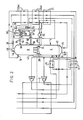
- FIG 2 there is illustrated a plant for performing an air separation cycle that is a modification of the cycle operated by the plant shown in Figure 1.
- the sub-cooler 23 is in two separate sections 23(a) and 23(b). In the higher temperature range section 23(a) there is cooled the liquid nitrogen stream withdrawn from the column 6 through the outlet 36. A part of this stream is further cooled in the section 23(b) prior to its passage through the valve 38. The remainder of the liquid nitrogen stream is passed from the section 23(a) of the sub-cooler 23, through an expansion or throttling valve 60 and into an additional liquid-vapour contact column 62 which employs the condenser 32 to reboil the liquid nitrogen.
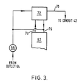
- the vaporised nitrogen is mixed with a stream of liquid oxygen.
- This stream of liquid oxygen is withdrawn through an outlet 64 from the bottom of the lower pressure column 8 and is pumped by a pump 66 through the sub-cooler 21 countercurrently to the oxygen-rich liquid withdrawn from the higher pressure column 6 through the outlet 26, in which sub-cooler 21 it is warmed to its saturation temperature at the operating pressure of the column, and into the top of the column 62 through an inlet 68.
- the column 62 there is thus a downward flow of liquid that becomes progressively richer in nitrogen and an upward flow of vapour that becomes progressively richer in oxygen.
- a mixed oxygen-nitrogen vapour stream is withdrawn from an intermediate level in the column (typically corresponding to an oxygen-nitrogen ratio the same as that in the incoming air) through outlet 70 and is passed through the section 23(a) of the sub-cooler 23, the sub-cooler 21 and the heat exchanger 17 cocurrently with the product nitrogen and waste nitrogen streams.
- the mixed oxygen-nitrogen stream then flows through the heat exchanger 2 cocurrently with the product nitrogen and waste nitrogen streams but for only a part of the extent of this heat exchanger and is then withdrawn and expanded with the performance of external work in a second turbine 72.
- refrigeration is generated and this refrigeration is utilised to provide cooling for the reversing heat exchanger 17.
- the gas leaving the outlet of the turbine 72 is merged with the waste nitrogen stream upstream of its entrance to the heat exchanger 2.
- the refrigeration duty imposed upon the air turbine 16 is thus reduced, and accordingly, the amount of air that needs to be withdrawn from the column 6 through the outlet 14 is similarly reduced. Therefore, air is fractionated in the column 4 at a greater rate than in the operation of the plant shown in Figure 1 and hence the argon-enriched vapour stream may be withdrawn from the lower pressure column 8 at a similarly greater rate, and thus the rate of processing the argon-enriched vapour in the column 34 can be matched with the increased refrigeration made available to the condenser 32.
- the higher pressure column 6 may operate at a pressure of about 6.5 atmospheres and the lower pressure column at an average pressure of about 1.7 atmospheres.
- the argon column 34 operates a similar average pressure to the lower pressure 8, and the pressure at which the liquid-vapour contact column 62 operates is typically in the order of about 2.7 atmospheres, there being a 1.5 K temperature difference between the boiling liquid nitrogen in the column 62 and the condensing argon returned to the column 34.
- the turbines 16 and 62 expand their respective gaseous feeds to the pressure of the waste nitrogen stream.
- the rate of passage of liquid oxygen and liquid nitrogen into the column 62 may be selected in accordance with the relative demand for oxygen and argon from the plant. It is to be appreciated that the mixing of the liquid oxygen and nitrogen streams in the column 62 will reduce the overall rate of production notwithstanding the increased rate of processing of air in comparison with the plant shown in Figure 1. Accordingly, the plant shown in Figure 2 may be constructed so as to give the operator of the plant the choice of shutting off all fluid flows to and from the additional column 62 so that the plant then operates analogously to the one shown in Figure 1.
- Such a mode of operation may be chosen when the demand for oxygen is relatively high, but if the oxygen demand falls the column 62 may be brought into operation so as to increase the rate of argon production by 8% by but at the expense of an 8% reduction in the rate of oxygen production.
Landscapes
- Engineering & Computer Science (AREA)
- Physics & Mathematics (AREA)
- Mechanical Engineering (AREA)
- Thermal Sciences (AREA)
- General Engineering & Computer Science (AREA)
- Health & Medical Sciences (AREA)
- Emergency Medicine (AREA)
- Separation By Low-Temperature Treatments (AREA)
Applications Claiming Priority (4)
| Application Number | Priority Date | Filing Date | Title |
|---|---|---|---|
| GB8628018 | 1986-11-24 | ||
| GB868628018A GB8628018D0 (en) | 1986-11-24 | 1986-11-24 | Air separation |
| GB878707993A GB8707993D0 (en) | 1986-11-24 | 1987-04-03 | Air separation |
| GB8707993 | 1987-04-03 |
Publications (3)
| Publication Number | Publication Date |
|---|---|
| EP0269342A2 true EP0269342A2 (de) | 1988-06-01 |
| EP0269342A3 EP0269342A3 (en) | 1989-03-01 |
| EP0269342B1 EP0269342B1 (de) | 1991-06-12 |
Family
ID=26291575
Family Applications (1)
| Application Number | Title | Priority Date | Filing Date |
|---|---|---|---|
| EP87310109A Expired EP0269342B1 (de) | 1986-11-24 | 1987-11-16 | Luftverflüssigung |
Country Status (7)
| Country | Link |
|---|---|
| US (1) | US4790866A (de) |
| EP (1) | EP0269342B1 (de) |
| JP (1) | JP2690914B2 (de) |
| AU (2) | AU602370B2 (de) |
| CA (1) | CA1294209C (de) |
| DE (1) | DE3770772D1 (de) |
| GB (1) | GB2198514B (de) |
Cited By (3)
| Publication number | Priority date | Publication date | Assignee | Title |
|---|---|---|---|---|
| EP0556503A1 (de) * | 1992-02-13 | 1993-08-25 | Air Products And Chemicals, Inc. | Verdampfung von Flüssigsauerstoff zwecks verbesserter Argonrückgewinnung |
| CN114763962A (zh) * | 2021-01-14 | 2022-07-19 | 气体产品与化学公司 | 流体回收方法和装置 |
| EP4214456B1 (de) * | 2020-09-17 | 2024-05-08 | Linde GmbH | Verfahren und vorrichtung zur kryogenen trennung von luft mit einer turbine für ein gasgemisch |
Families Citing this family (26)
| Publication number | Priority date | Publication date | Assignee | Title |
|---|---|---|---|---|
| US4777803A (en) * | 1986-12-24 | 1988-10-18 | Erickson Donald C | Air partial expansion refrigeration for cryogenic air separation |
| DE3834793A1 (de) * | 1988-10-12 | 1990-04-19 | Linde Ag | Verfahren zur gewinnung von rohargon |
| CN1025067C (zh) * | 1989-02-23 | 1994-06-15 | 琳德股份公司 | 精馏分离空气的方法及装置 |
| DE3913880A1 (de) * | 1989-04-27 | 1990-10-31 | Linde Ag | Verfahren und vorrichtung zur tieftemperaturzerlegung von luft |
| FR2655137B1 (fr) * | 1989-11-28 | 1992-10-16 | Air Liquide | Procede et installation de distillation d'air avec production d'argon. |
| US5077978A (en) * | 1990-06-12 | 1992-01-07 | Air Products And Chemicals, Inc. | Cryogenic process for the separation of air to produce moderate pressure nitrogen |
| US5129932A (en) * | 1990-06-12 | 1992-07-14 | Air Products And Chemicals, Inc. | Cryogenic process for the separation of air to produce moderate pressure nitrogen |
| GB9015377D0 (en) * | 1990-07-12 | 1990-08-29 | Boc Group Plc | Air separation |
| US5165245A (en) * | 1991-05-14 | 1992-11-24 | Air Products And Chemicals, Inc. | Elevated pressure air separation cycles with liquid production |
| US5165244A (en) * | 1991-05-14 | 1992-11-24 | Air Products And Chemicals, Inc. | Process to produce oxygen and nitrogen at medium pressure |
| US5161380A (en) * | 1991-08-12 | 1992-11-10 | Union Carbide Industrial Gases Technology Corporation | Cryogenic rectification system for enhanced argon production |
| US5235816A (en) * | 1991-10-10 | 1993-08-17 | Praxair Technology, Inc. | Cryogenic rectification system for producing high purity oxygen |
| US5255524A (en) * | 1992-02-13 | 1993-10-26 | Air Products & Chemicals, Inc. | Dual heat pump cycles for increased argon recovery |
| US5245831A (en) * | 1992-02-13 | 1993-09-21 | Air Products And Chemicals, Inc. | Single heat pump cycle for increased argon recovery |
| US5251450A (en) * | 1992-08-28 | 1993-10-12 | Air Products And Chemicals, Inc. | Efficient single column air separation cycle and its integration with gas turbines |
| AU659759B2 (en) * | 1992-10-01 | 1995-05-25 | Boc Group, Inc., The | Purification of argon by cryogenic adsorption |
| US5456083A (en) * | 1994-05-26 | 1995-10-10 | The Boc Group, Inc. | Air separation apparatus and method |
| US5469710A (en) * | 1994-10-26 | 1995-11-28 | Praxair Technology, Inc. | Cryogenic rectification system with enhanced argon recovery |
| US6397632B1 (en) | 2001-07-11 | 2002-06-04 | Praxair Technology, Inc. | Gryogenic rectification method for increased argon production |
| GB0422635D0 (en) | 2004-10-12 | 2004-11-10 | Air Prod & Chem | Process for the cryogenic distillation of air |
| US20130086941A1 (en) * | 2011-10-07 | 2013-04-11 | Henry Edward Howard | Air separation method and apparatus |
| US10337792B2 (en) | 2014-05-01 | 2019-07-02 | Praxair Technology, Inc. | System and method for production of argon by cryogenic rectification of air |
| US9291389B2 (en) * | 2014-05-01 | 2016-03-22 | Praxair Technology, Inc. | System and method for production of argon by cryogenic rectification of air |
| US10082333B2 (en) | 2014-07-02 | 2018-09-25 | Praxair Technology, Inc. | Argon condensation system and method |
| CN109676367A (zh) * | 2018-12-28 | 2019-04-26 | 乔治洛德方法研究和开发液化空气有限公司 | 一种热交换器组件及装配所述热交换器组件的方法 |
| US11933541B2 (en) * | 2021-08-11 | 2024-03-19 | Praxair Technology, Inc. | Cryogenic air separation unit with argon condenser vapor recycle |
Family Cites Families (9)
| Publication number | Priority date | Publication date | Assignee | Title |
|---|---|---|---|---|
| FR2041701B1 (de) * | 1969-05-05 | 1974-02-01 | Air Liquide | |
| DE2055099A1 (de) * | 1970-11-10 | 1972-05-18 | Messer Griesheim Gmbh, 6000 Frankfurt | Verfahren zur Anreicherung von Krypton und Xenon in Luftzerlegungsanlagen |
| DE2304976A1 (de) * | 1973-02-01 | 1974-08-08 | Linde Ag | Verfahren zur zerlegung von gasgemischen in drei bestandteile durch tieftemperatur-rektifikation |
| JPS59150286A (ja) * | 1983-02-15 | 1984-08-28 | 日本酸素株式会社 | アルゴンの製造方法 |
| JPS6151233A (ja) * | 1984-08-20 | 1986-03-13 | Usac Electronics Ind Co Ltd | プリンタにおける制御方法 |
| GB8512563D0 (en) * | 1985-05-17 | 1985-06-19 | Boc Group Plc | Air separation method |
| US4615716A (en) * | 1985-08-27 | 1986-10-07 | Air Products And Chemicals, Inc. | Process for producing ultra high purity oxygen |
| DE3610973A1 (de) * | 1986-04-02 | 1987-10-08 | Linde Ag | Verfahren und vorrichtung zur erzeugung von stickstoff |
| JPH0723414B2 (ja) * | 1986-06-16 | 1995-03-15 | 日本合成ゴム株式会社 | エチレン−α−オレフイン系共重合体の製造方法 |
-
1987
- 1987-11-16 DE DE8787310109T patent/DE3770772D1/de not_active Expired - Fee Related
- 1987-11-16 GB GB8726803A patent/GB2198514B/en not_active Expired - Fee Related
- 1987-11-16 EP EP87310109A patent/EP0269342B1/de not_active Expired
- 1987-11-20 US US07/123,492 patent/US4790866A/en not_active Expired - Lifetime
- 1987-11-23 CA CA000552460A patent/CA1294209C/en not_active Expired - Fee Related
- 1987-11-24 AU AU81651/87A patent/AU602370B2/en not_active Ceased
- 1987-11-24 AU AU81650/87A patent/AU603157B2/en not_active Ceased
- 1987-11-24 JP JP62295909A patent/JP2690914B2/ja not_active Expired - Lifetime
Cited By (6)
| Publication number | Priority date | Publication date | Assignee | Title |
|---|---|---|---|---|
| EP0556503A1 (de) * | 1992-02-13 | 1993-08-25 | Air Products And Chemicals, Inc. | Verdampfung von Flüssigsauerstoff zwecks verbesserter Argonrückgewinnung |
| EP4214456B1 (de) * | 2020-09-17 | 2024-05-08 | Linde GmbH | Verfahren und vorrichtung zur kryogenen trennung von luft mit einer turbine für ein gasgemisch |
| CN114763962A (zh) * | 2021-01-14 | 2022-07-19 | 气体产品与化学公司 | 流体回收方法和装置 |
| KR20220103052A (ko) * | 2021-01-14 | 2022-07-21 | 에어 프로덕츠 앤드 케미칼스, 인코오포레이티드 | 유체 회수 공정 및 장치 |
| EP4033186A1 (de) * | 2021-01-14 | 2022-07-27 | Air Products and Chemicals, Inc. | Verfahren und vorrichtung zur rückgewinnung von fluiden |
| CN114763962B (zh) * | 2021-01-14 | 2024-10-18 | 气体产品与化学公司 | 流体回收方法和装置 |
Also Published As
| Publication number | Publication date |
|---|---|
| DE3770772D1 (de) | 1991-07-18 |
| AU8165087A (en) | 1989-06-08 |
| EP0269342B1 (de) | 1991-06-12 |
| AU8165187A (en) | 1988-05-26 |
| CA1294209C (en) | 1992-01-14 |
| JP2690914B2 (ja) | 1997-12-17 |
| GB8726803D0 (en) | 1987-12-23 |
| GB2198514A (en) | 1988-06-15 |
| JPS63187087A (ja) | 1988-08-02 |
| GB2198514B (en) | 1990-09-19 |
| AU603157B2 (en) | 1990-11-08 |
| EP0269342A3 (en) | 1989-03-01 |
| US4790866A (en) | 1988-12-13 |
| AU602370B2 (en) | 1990-10-11 |
Similar Documents
| Publication | Publication Date | Title |
|---|---|---|
| EP0269342B1 (de) | Luftverflüssigung | |
| EP0633438B2 (de) | Lufttrennung | |
| US4883516A (en) | Air separation | |
| US5511381A (en) | Air separation | |
| EP0636845B1 (de) | Lufttrennung | |
| US5546766A (en) | Air separation | |
| EP0577349B1 (de) | Lufttrennung | |
| US5551258A (en) | Air separation | |
| US5485729A (en) | Air separation | |
| EP1243883A1 (de) | Luftzerlegung | |
| EP0269343A2 (de) | Luftverflüssigung | |
| US4717409A (en) | Liquid vapor contact method and apparatus | |
| US5692398A (en) | Production of argon | |
| US4747859A (en) | Air separation | |
| EP0752566B1 (de) | Lufttrennung | |
| US4747860A (en) | Air separation | |
| US4883517A (en) | Air separation | |
| EP0660058A2 (de) | Lufttrennung | |
| EP0333384A2 (de) | Lufttrennung | |
| AU679022B2 (en) | Air separation | |
| US4723975A (en) | Air separation method and apparatus |
Legal Events
| Date | Code | Title | Description |
|---|---|---|---|
| PUAI | Public reference made under article 153(3) epc to a published international application that has entered the european phase |
Free format text: ORIGINAL CODE: 0009012 |
|
| AK | Designated contracting states |
Kind code of ref document: A2 Designated state(s): BE CH DE FR IT LI NL |
|
| PUAL | Search report despatched |
Free format text: ORIGINAL CODE: 0009013 |
|
| AK | Designated contracting states |
Kind code of ref document: A3 Designated state(s): BE CH DE FR IT LI NL |
|
| 17P | Request for examination filed |
Effective date: 19890821 |
|
| 17Q | First examination report despatched |
Effective date: 19900412 |
|
| GRAA | (expected) grant |
Free format text: ORIGINAL CODE: 0009210 |
|
| AK | Designated contracting states |
Kind code of ref document: B1 Designated state(s): BE CH DE FR IT LI NL |
|
| ITF | It: translation for a ep patent filed | ||
| ET | Fr: translation filed | ||
| REF | Corresponds to: |
Ref document number: 3770772 Country of ref document: DE Date of ref document: 19910718 |
|
| PLBE | No opposition filed within time limit |
Free format text: ORIGINAL CODE: 0009261 |
|
| STAA | Information on the status of an ep patent application or granted ep patent |
Free format text: STATUS: NO OPPOSITION FILED WITHIN TIME LIMIT |
|
| 26N | No opposition filed | ||
| PGFP | Annual fee paid to national office [announced via postgrant information from national office to epo] |
Ref country code: FR Payment date: 19941013 Year of fee payment: 8 Ref country code: CH Payment date: 19941013 Year of fee payment: 8 |
|
| PGFP | Annual fee paid to national office [announced via postgrant information from national office to epo] |
Ref country code: DE Payment date: 19941026 Year of fee payment: 8 |
|
| PGFP | Annual fee paid to national office [announced via postgrant information from national office to epo] |
Ref country code: BE Payment date: 19941027 Year of fee payment: 8 |
|
| PGFP | Annual fee paid to national office [announced via postgrant information from national office to epo] |
Ref country code: NL Payment date: 19941130 Year of fee payment: 8 |
|
| PG25 | Lapsed in a contracting state [announced via postgrant information from national office to epo] |
Ref country code: LI Effective date: 19951130 Ref country code: CH Effective date: 19951130 Ref country code: BE Effective date: 19951130 |
|
| BERE | Be: lapsed |
Owner name: THE BOC GROUP P.L.C. Effective date: 19951130 |
|
| PG25 | Lapsed in a contracting state [announced via postgrant information from national office to epo] |
Ref country code: NL Effective date: 19960601 |
|
| REG | Reference to a national code |
Ref country code: CH Ref legal event code: PL |
|
| PG25 | Lapsed in a contracting state [announced via postgrant information from national office to epo] |
Ref country code: FR Effective date: 19960731 |
|
| NLV4 | Nl: lapsed or anulled due to non-payment of the annual fee |
Effective date: 19960601 |
|
| PG25 | Lapsed in a contracting state [announced via postgrant information from national office to epo] |
Ref country code: DE Effective date: 19960801 |
|
| REG | Reference to a national code |
Ref country code: FR Ref legal event code: ST |
|
| PG25 | Lapsed in a contracting state [announced via postgrant information from national office to epo] |
Ref country code: IT Free format text: LAPSE BECAUSE OF NON-PAYMENT OF DUE FEES;WARNING: LAPSES OF ITALIAN PATENTS WITH EFFECTIVE DATE BEFORE 2007 MAY HAVE OCCURRED AT ANY TIME BEFORE 2007. THE CORRECT EFFECTIVE DATE MAY BE DIFFERENT FROM THE ONE RECORDED. Effective date: 20051116 |