EP0269558A2 - Arbre électrique intégré avec un moteur à induction et son procédé de fabrication - Google Patents
Arbre électrique intégré avec un moteur à induction et son procédé de fabrication Download PDFInfo
- Publication number
- EP0269558A2 EP0269558A2 EP87810448A EP87810448A EP0269558A2 EP 0269558 A2 EP0269558 A2 EP 0269558A2 EP 87810448 A EP87810448 A EP 87810448A EP 87810448 A EP87810448 A EP 87810448A EP 0269558 A2 EP0269558 A2 EP 0269558A2
- Authority
- EP
- European Patent Office
- Prior art keywords
- stator
- arbor
- laminations
- sleeve
- increase
- Prior art date
- Legal status (The legal status is an assumption and is not a legal conclusion. Google has not performed a legal analysis and makes no representation as to the accuracy of the status listed.)
- Withdrawn
Links
- 230000006698 induction Effects 0.000 title claims abstract description 6
- 238000000034 method Methods 0.000 title claims description 3
- 238000004519 manufacturing process Methods 0.000 title description 2
- 238000003475 lamination Methods 0.000 claims abstract description 11
- 229920005989 resin Polymers 0.000 claims abstract description 11
- 239000011347 resin Substances 0.000 claims abstract description 11
- 238000013016 damping Methods 0.000 claims abstract description 4
- 239000000126 substance Substances 0.000 claims abstract 2
- 239000000463 material Substances 0.000 claims description 11
- 238000004804 winding Methods 0.000 claims description 11
- 238000009413 insulation Methods 0.000 claims description 8
- 239000004020 conductor Substances 0.000 claims description 6
- 230000003245 working effect Effects 0.000 claims description 4
- 230000000694 effects Effects 0.000 claims description 3
- 239000002184 metal Substances 0.000 claims description 3
- 229910052751 metal Inorganic materials 0.000 claims description 3
- 239000010935 stainless steel Substances 0.000 claims description 3
- 229910001220 stainless steel Inorganic materials 0.000 claims description 3
- 241000555745 Sciuridae Species 0.000 claims description 2
- 238000001816 cooling Methods 0.000 claims description 2
- 230000008595 infiltration Effects 0.000 claims description 2
- 238000001764 infiltration Methods 0.000 claims description 2
- 239000007788 liquid Substances 0.000 claims description 2
- RYGMFSIKBFXOCR-UHFFFAOYSA-N Copper Chemical compound [Cu] RYGMFSIKBFXOCR-UHFFFAOYSA-N 0.000 claims 1
- 229910045601 alloy Inorganic materials 0.000 claims 1
- 239000000956 alloy Substances 0.000 claims 1
- 239000010949 copper Substances 0.000 claims 1
- 229910052802 copper Inorganic materials 0.000 claims 1
- 238000002425 crystallisation Methods 0.000 claims 1
- 230000008025 crystallization Effects 0.000 claims 1
- 239000002923 metal particle Substances 0.000 claims 1
- 229910052709 silver Inorganic materials 0.000 claims 1
- 239000004332 silver Substances 0.000 claims 1
- 238000010276 construction Methods 0.000 description 4
- 238000000227 grinding Methods 0.000 description 4
- 239000010432 diamond Substances 0.000 description 3
- 238000005461 lubrication Methods 0.000 description 3
- 238000003801 milling Methods 0.000 description 3
- 230000003068 static effect Effects 0.000 description 3
- 229910000831 Steel Inorganic materials 0.000 description 2
- 239000013043 chemical agent Substances 0.000 description 2
- 239000000110 cooling liquid Substances 0.000 description 2
- 230000008878 coupling Effects 0.000 description 2
- 238000010168 coupling process Methods 0.000 description 2
- 238000005859 coupling reaction Methods 0.000 description 2
- 239000002245 particle Substances 0.000 description 2
- 238000007789 sealing Methods 0.000 description 2
- 239000010959 steel Substances 0.000 description 2
- 238000007514 turning Methods 0.000 description 2
- 229910052582 BN Inorganic materials 0.000 description 1
- PZNSFCLAULLKQX-UHFFFAOYSA-N Boron nitride Chemical compound N#B PZNSFCLAULLKQX-UHFFFAOYSA-N 0.000 description 1
- 229910000669 Chrome steel Inorganic materials 0.000 description 1
- 239000011230 binding agent Substances 0.000 description 1
- 239000000919 ceramic Substances 0.000 description 1
- 229910003460 diamond Inorganic materials 0.000 description 1
- 239000006185 dispersion Substances 0.000 description 1
- 238000005553 drilling Methods 0.000 description 1
- 238000010292 electrical insulation Methods 0.000 description 1
- 238000005516 engineering process Methods 0.000 description 1
- 239000003822 epoxy resin Substances 0.000 description 1
- 238000005242 forging Methods 0.000 description 1
- 239000004519 grease Substances 0.000 description 1
- 238000003754 machining Methods 0.000 description 1
- 238000005259 measurement Methods 0.000 description 1
- 239000003595 mist Substances 0.000 description 1
- 239000000203 mixture Substances 0.000 description 1
- 229920000647 polyepoxide Polymers 0.000 description 1
- 230000005855 radiation Effects 0.000 description 1
- 239000004576 sand Substances 0.000 description 1
- 239000007787 solid Substances 0.000 description 1
- 238000006467 substitution reaction Methods 0.000 description 1
- 229920002994 synthetic fiber Polymers 0.000 description 1
- XLYOFNOQVPJJNP-UHFFFAOYSA-N water Substances O XLYOFNOQVPJJNP-UHFFFAOYSA-N 0.000 description 1
Images


Classifications
-
- H—ELECTRICITY
- H02—GENERATION; CONVERSION OR DISTRIBUTION OF ELECTRIC POWER
- H02K—DYNAMO-ELECTRIC MACHINES
- H02K7/00—Arrangements for handling mechanical energy structurally associated with dynamo-electric machines, e.g. structural association with mechanical driving motors or auxiliary dynamo-electric machines
- H02K7/14—Structural association with mechanical loads, e.g. with hand-held machine tools or fans
- H02K7/16—Structural association with mechanical loads, e.g. with hand-held machine tools or fans for operation above the critical speed of vibration of the rotating parts
-
- H—ELECTRICITY
- H02—GENERATION; CONVERSION OR DISTRIBUTION OF ELECTRIC POWER
- H02K—DYNAMO-ELECTRIC MACHINES
- H02K17/00—Asynchronous induction motors; Asynchronous induction generators
- H02K17/02—Asynchronous induction motors
- H02K17/16—Asynchronous induction motors having rotors with internally short-circuited windings, e.g. cage rotors
-
- Y—GENERAL TAGGING OF NEW TECHNOLOGICAL DEVELOPMENTS; GENERAL TAGGING OF CROSS-SECTIONAL TECHNOLOGIES SPANNING OVER SEVERAL SECTIONS OF THE IPC; TECHNICAL SUBJECTS COVERED BY FORMER USPC CROSS-REFERENCE ART COLLECTIONS [XRACs] AND DIGESTS
- Y10—TECHNICAL SUBJECTS COVERED BY FORMER USPC
- Y10T—TECHNICAL SUBJECTS COVERED BY FORMER US CLASSIFICATION
- Y10T29/00—Metal working
- Y10T29/49—Method of mechanical manufacture
- Y10T29/49002—Electrical device making
- Y10T29/49009—Dynamoelectric machine
-
- Y—GENERAL TAGGING OF NEW TECHNOLOGICAL DEVELOPMENTS; GENERAL TAGGING OF CROSS-SECTIONAL TECHNOLOGIES SPANNING OVER SEVERAL SECTIONS OF THE IPC; TECHNICAL SUBJECTS COVERED BY FORMER USPC CROSS-REFERENCE ART COLLECTIONS [XRACs] AND DIGESTS
- Y10—TECHNICAL SUBJECTS COVERED BY FORMER USPC
- Y10T—TECHNICAL SUBJECTS COVERED BY FORMER US CLASSIFICATION
- Y10T408/00—Cutting by use of rotating axially moving tool
- Y10T408/65—Means to drive tool
-
- Y—GENERAL TAGGING OF NEW TECHNOLOGICAL DEVELOPMENTS; GENERAL TAGGING OF CROSS-SECTIONAL TECHNOLOGIES SPANNING OVER SEVERAL SECTIONS OF THE IPC; TECHNICAL SUBJECTS COVERED BY FORMER USPC CROSS-REFERENCE ART COLLECTIONS [XRACs] AND DIGESTS
- Y10—TECHNICAL SUBJECTS COVERED BY FORMER USPC
- Y10T—TECHNICAL SUBJECTS COVERED BY FORMER US CLASSIFICATION
- Y10T409/00—Gear cutting, milling, or planing
- Y10T409/30—Milling
- Y10T409/309352—Cutter spindle or spindle support
Definitions
- This invention has as its object an electric arbor integrated with an induction motor for frequencies up to and beyond 3000 Hz, suitable for mechanical workings, making possible high performances (precision, speed, power and life) extreme compactness (very limited weight and size), notable modularity (versatility in use) and low cost, characterized in that the extreme precision is concentrated in the sleeve of the arbor, while the compactness is governed by the stator and rotor.
- the object of the invention is the process for making the electric arbor characterized by the characterizing part of claim 3.
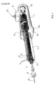
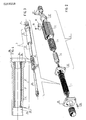
- said electric arbor, fig. 1 is made up of a sleeve 3 (fig. 3 and 4) inside of which is inserted arbor shaft 23 (fig. 1 and 3) supported by bearings 6 (fig. 1 and 3) and by the group of bearings 6 ⁇ and 6 ⁇ (fig. 1 and 3); induction motor 2 (fig. 1 and 2) is fastened by four screws 26 (fig. 1 and 2) cantilevered by flanges 25 (fig. 1 and 2).
- Rotor 5 (fig. 2 and 9) which translates the electromagnetic energy into mechanical energy is mounted, also cantilevered, on the arbor shaft.
- Sleeve 3 (fig. 3 and 4) comprises two coaxial tubular parts 3 ⁇ and 3 ⁇ (fig. 3 and 4); they are made from remelted chrome steel, preshaped by forging, successively worked by chip removal, then core thermally treated (including cooling at -70°C) (hardness: 62 HRC). The working of the two parts is initially normal, i.e., each single part is worked independently of the other.
- the shoulders at distance 3′′′ of outside part 3 ⁇ will have the identical dimension of the shoulders of inside part 3 ⁇ .
- the two inside seats 35 ⁇ and 36 ⁇ (fig. 4) of part 3 ⁇ are ground while respective seats 35 and 36 are ground, thus obtaining a very close tolerance of concentricity which does not exceed the value of 0.002 mm.
- Part 3 ⁇ finally will undergo another operation of removal of the head which was used for workings performed together with part 3 ⁇ (fig. 4).
- sleeve 3 (fig. 3 and 4) is finished with a diamond grinding wheel with resin binder to obtain a slight roughness (Ra: 0.08-0.15 ⁇ m) and very limited machining tolerances: nominal diameter +0.002/+0.004 mm; roundness within 0.001 mm and cylindricality, over the entire length of the sleeve, within 0.0015 mm.
- the sleeve can be mounted in a bushing with ball bearing cage allowing the dynamic rectilinear movement of the electric arbor with great precision and rigidity.
- bearings 6, 6 ⁇ and 6 ⁇ (fig. 1 and 3) of very great precision, matched at the manufacturer's to have absolute guarantee of desired prestress values without having to perform any measurement or adjustment.
- the particular method of making sleeve 3 and the materials selected for the two components 3 ⁇ and 3 ⁇ guarantee the perfect functioning even with temperature variations; actually the possible expansion difference, for the two parts in question 3 ⁇ and 3 ⁇ (fig. 4) is so small as to be practically insignificant and in any case would be translated into a load variation far less than the load variations that arbor 1 (fig. 1 and 2) must support because of the work that it must perform.
- Arbor shaft 23 (fig. 1 and 3), made of case-hardened, tempered steel (hardness 60 HRC), is provided in various shapes of the front end part ("nose"): -- for clamping of tool 30 (fig. 1) by means of a chuck 29 and relative nut 28 (fig. 1); -- for holding of conical tools clamped by means of a nut; -- for holding conical tools with fast coupling and uncoupling; -- for tools or tool-holders with flange clamp
- the version of the arbor shaft is also provided with a central bore for bringing in of cooling liquid and/or lubrication of the tool, since in many cases, given the high speed of rotation, the cooling liquid and/or lubrication made to come to the tool by an outside jet actually does not reach the tool because of the vortex produced by the tool itself.
- a dynamic and static sealing device 24 (fig. 1 and 3). It is a gasket that does not allow infiltration of liquids and solid particles which otherwise would seriously damage bearings 6 ⁇ and 6 ⁇ .
- the feature of said device 24 consists in the fact that when the electric arbor is stopped, the gasket, made of a synthetic material resistant to very many chemical agents, presses against a thermally treated, lapped steel washer; when the unit is in operation said gasket first lightens the pressure against the washer, then, when a certain number of rpms is reached, the gasket is removed completely by centrifugal effect to allow the highest rotation condition without the minimum friction.
- Stator 4 (fig. 2 and 5) of the electric arbor in question, according to the invention, is made up of magnetic laminations (fig. 6) of very small thickness, to allow small losses even at high frequencies up to and beyond 3000 Hz, and incorporated with epoxy resin 14 (fig. 5 and 7) charged with sand particles which improve the thermal conductivity without compromising its electrical insulation which results from very high resistivity.
- the composition of the material from which the laminations (fig.6) are made is such as to allow a high magnetic saturation, so a proportioning has been sought in stator slots 8 (fig. 6), outside ring 7 (fig. 6) and teeth 9 (fig.
- insulations 10 (fig.7) of the stator slots to allow a considerable reduction of the thickness of said insulations 10 without compromising the insulation of the stator.
- resin 14 (fig. 5 and 7) is decisive, which is inserted hot and accelerates the individual molecules of the resin, which being placed between the coils of winding 13 (fig.7) and between the winding 13 itself and frame 12, 12 ⁇ and 12 ⁇ (fig. 5) and winding 13 itself and frame 12, 12 ⁇ and 12 ⁇ (fig. 5) and core track 4 ⁇ (fig. 5) guarantees the final result and gives the stator thus constructed great reliability in time.
- Rotor 5 (fig. 1 and 9) made with magnetic laminations (fig. 10) with low loss and slight thickness, dimensioned for low-resistance conductors makes it possible to use a larger than normal shaft.
- the construction is particularly sturdy thanks to rings 17 (fig. 9), housings 20 (fig. 9) of stainless steel and with the damping resin that neutralizes the effects of resonance to which conductors 16 (fig. 9) are subjected allows very high rotation speeds while allowing a good service life of the bearings.
- This rotor thus constructed, makes it possible to dimension the diameter of the rotor itself greater than normal, by which a notably higher torque is available even at low rotation conditions.
- the "modular" construction i.e., with easily interchangeable groups, allows the achievement of units that reasonably meet a large number of specific requirements; also allowing easy updating of the same unit to adapt it to the ever faster development of the market which the user must face.
- an electric arbor made according to the invention can attain allows the use of highly productive tools, for example: of hard metal, ceramics, natural diamonds, synthetic diamonds and boron nitride.
Landscapes
- Engineering & Computer Science (AREA)
- Power Engineering (AREA)
- Iron Core Of Rotating Electric Machines (AREA)
- Manufacture Of Motors, Generators (AREA)
- Connection Of Motors, Electrical Generators, Mechanical Devices, And The Like (AREA)
Applications Claiming Priority (2)
| Application Number | Priority Date | Filing Date | Title |
|---|---|---|---|
| CH4690/86A CH670412A5 (fr) | 1986-11-24 | 1986-11-24 | |
| CH4690/86 | 1986-11-24 |
Publications (2)
| Publication Number | Publication Date |
|---|---|
| EP0269558A2 true EP0269558A2 (fr) | 1988-06-01 |
| EP0269558A3 EP0269558A3 (fr) | 1989-03-15 |
Family
ID=4280808
Family Applications (1)
| Application Number | Title | Priority Date | Filing Date |
|---|---|---|---|
| EP87810448A Withdrawn EP0269558A3 (fr) | 1986-11-24 | 1987-08-04 | Arbre électrique intégré avec un moteur à induction et son procédé de fabrication |
Country Status (4)
| Country | Link |
|---|---|
| US (2) | US4796353A (fr) |
| EP (1) | EP0269558A3 (fr) |
| JP (1) | JPS6485546A (fr) |
| CH (1) | CH670412A5 (fr) |
Cited By (2)
| Publication number | Priority date | Publication date | Assignee | Title |
|---|---|---|---|---|
| EP0903833A1 (fr) * | 1997-09-18 | 1999-03-24 | Siemens Aktiengesellschaft | Machine électrique avec rotor à cage d'écureil |
| EP3598618A1 (fr) * | 2018-07-19 | 2020-01-22 | Siemens Mobility GmbH | Machine rotative dynamoélectrique dotée des éléments de réduction de bruits tonals |
Families Citing this family (8)
| Publication number | Priority date | Publication date | Assignee | Title |
|---|---|---|---|---|
| CH670412A5 (fr) * | 1986-11-24 | 1989-06-15 | Tecnodelta | |
| DK157391A (da) * | 1991-09-06 | 1993-03-07 | Danfoss Flensburg Gmbh | Rotor til en elektrisk maskine |
| US5522124A (en) * | 1994-05-18 | 1996-06-04 | Cogsdill Tool Products, Inc. | Roller burnishing apparatus having directly driven, coaxially disposed burnishing head assembly |
| ES2147489B1 (es) * | 1997-05-19 | 2001-04-01 | Danobat | Acoplamiento del husillo del cabezal al rotor en un torno. |
| US6951256B1 (en) * | 2004-04-24 | 2005-10-04 | Ru Song Xiao | Machine tool having coaxial driving device |
| BE1018854A3 (nl) | 2009-08-11 | 2011-10-04 | Atlas Copco Airpower Nv | Droger voor samengeperst gas en werkwijze daarbij toegepast. |
| CN102039430B (zh) * | 2009-10-19 | 2012-11-28 | 达航工业股份有限公司 | 可换刀的小型化心轴单元以及主轴装置 |
| JP6298086B2 (ja) * | 2016-02-24 | 2018-03-20 | ファナック株式会社 | 電動機のロータ及びその製造方法 |
Family Cites Families (10)
| Publication number | Priority date | Publication date | Assignee | Title |
|---|---|---|---|---|
| GB272987A (en) * | 1926-03-18 | 1927-06-20 | Sydney Dale | Improvements in or relating to electric motors |
| GB317291A (en) * | 1928-06-13 | 1929-08-15 | Frederick Newton | Improvements in and relating to electric motors for driving spinning cans and the like |
| DE1760929B2 (de) * | 1968-07-20 | 1972-12-14 | Antriebsvorrichtung fuer eine trommelwaschmaschine | |
| GB1264078A (fr) * | 1970-06-08 | 1972-02-16 | ||
| JPS5060705A (fr) * | 1973-10-01 | 1975-05-24 | ||
| FR2266575B1 (fr) * | 1974-04-08 | 1976-12-17 | Roulements Soc Nouvelle | |
| DE3274074D1 (en) * | 1982-01-08 | 1986-12-11 | Fanuc Ltd | A spindle head unit |
| DE3340857A1 (de) * | 1983-11-11 | 1985-05-23 | Schaeffler Waelzlager Kg | Lagerung einer welle in der bohrung eines gehaeuses |
| DE3509635C1 (de) * | 1985-03-16 | 1986-02-06 | Index-Werke Kg Hahn & Tessky, 7300 Esslingen | Werkzeughalteeinrichtung fuer Drehmaschinen |
| CH670412A5 (fr) * | 1986-11-24 | 1989-06-15 | Tecnodelta |
-
1986
- 1986-11-24 CH CH4690/86A patent/CH670412A5/it not_active IP Right Cessation
-
1987
- 1987-07-29 US US07/079,029 patent/US4796353A/en not_active Expired - Fee Related
- 1987-08-04 EP EP87810448A patent/EP0269558A3/fr not_active Withdrawn
- 1987-11-17 JP JP62291675A patent/JPS6485546A/ja active Pending
-
1988
- 1988-07-25 US US07/233,968 patent/US4916341A/en not_active Expired - Fee Related
Cited By (3)
| Publication number | Priority date | Publication date | Assignee | Title |
|---|---|---|---|---|
| EP0903833A1 (fr) * | 1997-09-18 | 1999-03-24 | Siemens Aktiengesellschaft | Machine électrique avec rotor à cage d'écureil |
| EP3598618A1 (fr) * | 2018-07-19 | 2020-01-22 | Siemens Mobility GmbH | Machine rotative dynamoélectrique dotée des éléments de réduction de bruits tonals |
| US11539275B2 (en) | 2018-07-19 | 2022-12-27 | Siemens Mobility GmbH | Dynamoelectric rotary machine with elements for reducing tonal noises |
Also Published As
| Publication number | Publication date |
|---|---|
| CH670412A5 (fr) | 1989-06-15 |
| US4916341A (en) | 1990-04-10 |
| US4796353A (en) | 1989-01-10 |
| JPS6485546A (en) | 1989-03-30 |
| EP0269558A3 (fr) | 1989-03-15 |
Similar Documents
| Publication | Publication Date | Title |
|---|---|---|
| US4796353A (en) | Process for producing an electric arbor integrated with an induction motor | |
| CA2763291C (fr) | Outil pneumatique avec generateur d'electricite integre | |
| US4549341A (en) | Method for producing a permanent magnet rotor | |
| US5028830A (en) | Rotor apparatus for axial field electromagnetic devices | |
| US3299304A (en) | Laminated core having low compressibility characteristics for an electrical inductive device | |
| US20190238016A1 (en) | Rotor for an electric machine, electric machine with the rotor and to method for producing the rotor | |
| US3320660A (en) | Methods for assembling end shield members in dynamoelectric machines | |
| US5525851A (en) | Apparatus for producing high-speed rotation | |
| JP4566336B2 (ja) | 同期機ロータ | |
| CN110932438A (zh) | 具有端轴的用于异步电力机器的转子 | |
| Boglietti et al. | About the design of very high frequency induction motors for spindle applications | |
| US4888510A (en) | Rotary electric machine | |
| US4590668A (en) | Method of and apparatus for assembling dynamoelectric machine | |
| US2802124A (en) | High speed short-circuited rotor | |
| US11811280B2 (en) | Squirrel-cage rotor and associated asynchronous electrical machine | |
| US2703849A (en) | Rotor for dynamoelectric machines and the method of making | |
| US3258624A (en) | Snap ring assembly for securing a rotor to a shaft | |
| CN213185843U (zh) | 一种轴向磁场电机 | |
| WO2000064029A1 (fr) | Element de retenue d'arbre induit | |
| CN113441906A (zh) | 一种汽车发电机外壳的加工工艺 | |
| WO1994000904A1 (fr) | Moteur a induction a plusieurs niveaux | |
| US2590525A (en) | Dynamoelectric machine construction | |
| KR200166027Y1 (ko) | 시동전동기 회전자 코일 고정링 | |
| Boglietti et al. | About the design of very high frequency induction motors for spindle applications | |
| CN210093044U (zh) | 用于动力工具的电动马达 |
Legal Events
| Date | Code | Title | Description |
|---|---|---|---|
| PUAI | Public reference made under article 153(3) epc to a published international application that has entered the european phase |
Free format text: ORIGINAL CODE: 0009012 |
|
| AK | Designated contracting states |
Kind code of ref document: A2 Designated state(s): AT BE DE ES FR GB GR IT LU NL SE |
|
| PUAL | Search report despatched |
Free format text: ORIGINAL CODE: 0009013 |
|
| RHK1 | Main classification (correction) |
Ipc: H02K 7/16 |
|
| AK | Designated contracting states |
Kind code of ref document: A3 Designated state(s): AT BE DE ES FR GB GR IT LU NL SE |
|
| 17P | Request for examination filed |
Effective date: 19890615 |
|
| 17Q | First examination report despatched |
Effective date: 19910507 |
|
| STAA | Information on the status of an ep patent application or granted ep patent |
Free format text: STATUS: THE APPLICATION HAS BEEN WITHDRAWN |
|
| 18W | Application withdrawn |
Withdrawal date: 19920912 |
|
| RIN1 | Information on inventor provided before grant (corrected) |
Inventor name: MANTOVANI, ELIS |