EP0903833A1 - Machine électrique avec rotor à cage d'écureil - Google Patents
Machine électrique avec rotor à cage d'écureil Download PDFInfo
- Publication number
- EP0903833A1 EP0903833A1 EP98116861A EP98116861A EP0903833A1 EP 0903833 A1 EP0903833 A1 EP 0903833A1 EP 98116861 A EP98116861 A EP 98116861A EP 98116861 A EP98116861 A EP 98116861A EP 0903833 A1 EP0903833 A1 EP 0903833A1
- Authority
- EP
- European Patent Office
- Prior art keywords
- rotor
- stator
- electrical machine
- core
- rings
- Prior art date
- Legal status (The legal status is an assumption and is not a legal conclusion. Google has not performed a legal analysis and makes no representation as to the accuracy of the status listed.)
- Withdrawn
Links
- 241000555745 Sciuridae Species 0.000 title description 2
- 238000004804 winding Methods 0.000 claims description 16
- 239000000945 filler Substances 0.000 claims description 3
- 239000011810 insulating material Substances 0.000 claims description 2
- 238000001816 cooling Methods 0.000 description 3
- RYGMFSIKBFXOCR-UHFFFAOYSA-N Copper Chemical compound [Cu] RYGMFSIKBFXOCR-UHFFFAOYSA-N 0.000 description 2
- 229910052802 copper Inorganic materials 0.000 description 2
- 239000010949 copper Substances 0.000 description 2
- 230000015572 biosynthetic process Effects 0.000 description 1
- 239000002826 coolant Substances 0.000 description 1
- 230000007797 corrosion Effects 0.000 description 1
- 238000005260 corrosion Methods 0.000 description 1
- 238000013016 damping Methods 0.000 description 1
- 230000006866 deterioration Effects 0.000 description 1
- 239000004033 plastic Substances 0.000 description 1
- 239000002985 plastic film Substances 0.000 description 1
- 229920006255 plastic film Polymers 0.000 description 1
- 230000001681 protective effect Effects 0.000 description 1
- 125000006850 spacer group Chemical group 0.000 description 1
- 230000001360 synchronised effect Effects 0.000 description 1
- 238000009423 ventilation Methods 0.000 description 1
Images


Classifications
-
- H—ELECTRICITY
- H02—GENERATION; CONVERSION OR DISTRIBUTION OF ELECTRIC POWER
- H02K—DYNAMO-ELECTRIC MACHINES
- H02K3/00—Details of windings
- H02K3/04—Windings characterised by the conductor shape, form or construction, e.g. with bar conductors
- H02K3/12—Windings characterised by the conductor shape, form or construction, e.g. with bar conductors arranged in slots
-
- H—ELECTRICITY
- H02—GENERATION; CONVERSION OR DISTRIBUTION OF ELECTRIC POWER
- H02K—DYNAMO-ELECTRIC MACHINES
- H02K17/00—Asynchronous induction motors; Asynchronous induction generators
- H02K17/02—Asynchronous induction motors
- H02K17/16—Asynchronous induction motors having rotors with internally short-circuited windings, e.g. cage rotors
-
- H—ELECTRICITY
- H02—GENERATION; CONVERSION OR DISTRIBUTION OF ELECTRIC POWER
- H02K—DYNAMO-ELECTRIC MACHINES
- H02K2205/00—Specific aspects not provided for in the other groups of this subclass relating to casings, enclosures, supports
- H02K2205/12—Machines characterised by means for reducing windage losses or windage noise
-
- H—ELECTRICITY
- H02—GENERATION; CONVERSION OR DISTRIBUTION OF ELECTRIC POWER
- H02K—DYNAMO-ELECTRIC MACHINES
- H02K3/00—Details of windings
- H02K3/46—Fastening of windings on the stator or rotor structure
- H02K3/50—Fastening of winding heads, equalising connectors, or connections thereto
Definitions
- the invention relates to an electrical machine with a rotor laminated core arranged on a rotor shaft, in which Runner bars are arranged, which on the end faces of the runner sheet stack protruding runner bars by each a short-circuit ring electrically and mechanically with each other are connected and with a through a cylindrical gap separate from the rotor laminated core package, the with Stator coils is assembled, the front of the stator core form protruding stator coil winding heads.
- Synchronous machines come as electrical machines of this type with damper cage and asynchronous machines with cage rotor in Consideration.
- An asynchronous machine of this type is from DE-40 14 116 A1 known.
- DE 195 25 704 C1 describes an encapsulated rotor for one Asynchronous motor as a wet-running motor for driving a circular pump known.
- the rotor core is made of a corrosion-resistant Protective jacket protected against the coolant.
- DE-40 03 155 A1 is a forced ventilation known electrical machine with claw-pole rotor, whereby to form air ducts plastic ring walls between the stator core and the end shields arranged are. After all, it is with a collector motor for household appliances known from DE-87 12 026.7 U1 for noise reduction, the runner and / or stator core by wrapping with To provide plastic film with smooth outer surfaces.
- DE-A-23 61 764 describes an asynchronous machine with a squirrel-cage rotor known, in particular in grooves of the rotor core rotor bars made of copper are arranged, whose end faces protrude beyond the rotor laminated core each with a short-circuit ring, electrically and mechanically are interconnected. Is on the rotor shaft the rotor laminated core between support rings or end plates held. The rotor rotates at a cylindrical distance Gap in the hole of the stator core, where stator coils are arranged in the slots of the stator core are protruding from the stator core Form stator coil ends.
- EP-0 749 198 A2 are for damping the natural vibrations of the cage rotor an asynchronous machine on both sides of the rotor laminated core Spacers and preferably in one piece with them trained support rings provided, such that each short-circuit ring in the radial direction by one on the rotor shaft tight support ring is supported and the short-circuit ring by an associated shrink ring that the Short-circuit ring surrounds, is pressed onto the support ring. Also a relatively complex short-circuit rotor of this type works at higher speeds with relatively strong running noise.
- the object of the invention is in an electrical machine of the type mentioned at the outset to reduce the sound power level.
- the advantage of Invention is particularly seen in the fact that the shield the edges or protrusions leading to noise between the rotating rotor bars and the coil legs or winding heads of the stator core is avoided and a relatively smooth surface of the stand heads in the area the coil legs protruding from the stator core and forms end windings.
- An advantageous embodiment of the invention is the Features of claim 2 characterized.
- Another Execution of the invention is that the rings are cylindrical are, for example, in the axial extension of the stator core stack between stator and rotor flow edges Avoid on the stator coil winding heads.
- bridging elements are provided, which are substantially cylindrical up to a conical, closed winding end diameter form in which the runner bars and short-circuit rings of the runner rotate.
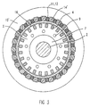
- FIG. 1 is on the rotor shaft 2 of the rotor 1 of an electrical machine, for example an asynchronous machine, a rotor core 3, consisting made of dynamo sheets, pressed on, both sides of the rotor sheet stack Support rings 7, 8, end plates or end plates are provided, which are firmly connected to the rotor shaft, e.g. are shrunk onto them.
- a squirrel cage are several rotor bars axially through the rotor laminated core 4, in particular made of copper, the front rotor bars 4 ', 4' 'protruding from the rotor laminated core electrically and mechanically connected to short-circuit rings 5, 6 are.
- Cooling air holes 9 can be guided through the rotor laminated core.
- the electric machine further includes one under formation a cylindrical gap 16 arranged around the rotor 1 Stand 10.
- the stand 10 consists of a stator core 10 ', in which a plurality of stator coils 11 are arranged, wherein from the stator core package with coil legs the stator coil end windings 12, 13 are led out.
- rotor 1 is a shield 14, 15 or 14 'provided.
- deposits form 14 ', bridging elements or filler pieces between the coil legs or winding heads 12, 13 of the stator core 10 'die for a smooth surface in the winding head inside diameter of the stand 10 provides shielding against the rotating Runner parts 4 ', 4' ', 5, 6.
Landscapes
- Engineering & Computer Science (AREA)
- Power Engineering (AREA)
- Iron Core Of Rotating Electric Machines (AREA)
- Insulation, Fastening Of Motor, Generator Windings (AREA)
Applications Claiming Priority (2)
| Application Number | Priority Date | Filing Date | Title |
|---|---|---|---|
| DE19741200 | 1997-09-18 | ||
| DE1997141200 DE19741200C1 (de) | 1997-09-18 | 1997-09-18 | Elektrische Maschine |
Publications (1)
| Publication Number | Publication Date |
|---|---|
| EP0903833A1 true EP0903833A1 (fr) | 1999-03-24 |
Family
ID=7842833
Family Applications (1)
| Application Number | Title | Priority Date | Filing Date |
|---|---|---|---|
| EP98116861A Withdrawn EP0903833A1 (fr) | 1997-09-18 | 1998-09-07 | Machine électrique avec rotor à cage d'écureil |
Country Status (2)
| Country | Link |
|---|---|
| EP (1) | EP0903833A1 (fr) |
| DE (1) | DE19741200C1 (fr) |
Cited By (1)
| Publication number | Priority date | Publication date | Assignee | Title |
|---|---|---|---|---|
| EP3598618A1 (fr) * | 2018-07-19 | 2020-01-22 | Siemens Mobility GmbH | Machine rotative dynamoélectrique dotée des éléments de réduction de bruits tonals |
Families Citing this family (4)
| Publication number | Priority date | Publication date | Assignee | Title |
|---|---|---|---|---|
| FR2903245B1 (fr) * | 2006-06-28 | 2015-03-27 | Valeo Equip Electr Moteur | Stator pour machine electrique tournante et machine electrique tournante comportant un tel stator |
| DE602008005838D1 (de) | 2008-02-27 | 2011-05-12 | Alstom Technology Ltd | Ventilatorkühlung eines Elektroantriebs |
| EP2528204B1 (fr) * | 2011-05-27 | 2017-12-27 | ABB Schweiz AG | Rotor à cage d'écureuil solide pour machine à induction et son procédé de fabrication |
| EP3544154A1 (fr) * | 2018-03-19 | 2019-09-25 | Siemens Aktiengesellschaft | Machine rotative dynamoélectrique pourvue de recouvrements d'encoche |
Citations (4)
| Publication number | Priority date | Publication date | Assignee | Title |
|---|---|---|---|---|
| US4546279A (en) * | 1984-05-07 | 1985-10-08 | Westinghouse Electric Corp. | Dynamoelectric machine with rotor ventilation system including exhaust coolant gas diffuser and noise baffle |
| EP0269558A2 (fr) * | 1986-11-24 | 1988-06-01 | Tecnodelta S.A. | Arbre électrique intégré avec un moteur à induction et son procédé de fabrication |
| GB2239128A (en) * | 1989-10-31 | 1991-06-19 | Mitsubishi Electric Corp | Noise reduction in air cooled induction rotary electric machine |
| JPH07288944A (ja) * | 1994-04-13 | 1995-10-31 | Meidensha Corp | 誘導電動機の通風音防止構造 |
Family Cites Families (6)
| Publication number | Priority date | Publication date | Assignee | Title |
|---|---|---|---|---|
| CH560479A5 (fr) * | 1972-12-19 | 1975-03-27 | Asea Ab | |
| DE8712026U1 (de) * | 1987-09-04 | 1988-07-07 | Siemens AG, 1000 Berlin und 8000 München | Kollektormotor zum Antrieb von Hausgeräten, insbesondere Waschmaschinen |
| DE4003155A1 (de) * | 1990-02-03 | 1991-08-29 | Bosch Gmbh Robert | Elektrische maschine mit fremdbelueftung |
| DE4014116A1 (de) * | 1990-05-02 | 1991-11-07 | Loher Ag | Asynchronmaschine |
| DE19521700A1 (de) * | 1995-06-14 | 1996-12-19 | Abb Daimler Benz Transp | Käfigläufer für eine Asynchronmaschine |
| DE19525704C1 (de) * | 1995-07-14 | 1996-07-25 | Grundfos As | Gekapselter Rotor |
-
1997
- 1997-09-18 DE DE1997141200 patent/DE19741200C1/de not_active Expired - Fee Related
-
1998
- 1998-09-07 EP EP98116861A patent/EP0903833A1/fr not_active Withdrawn
Patent Citations (4)
| Publication number | Priority date | Publication date | Assignee | Title |
|---|---|---|---|---|
| US4546279A (en) * | 1984-05-07 | 1985-10-08 | Westinghouse Electric Corp. | Dynamoelectric machine with rotor ventilation system including exhaust coolant gas diffuser and noise baffle |
| EP0269558A2 (fr) * | 1986-11-24 | 1988-06-01 | Tecnodelta S.A. | Arbre électrique intégré avec un moteur à induction et son procédé de fabrication |
| GB2239128A (en) * | 1989-10-31 | 1991-06-19 | Mitsubishi Electric Corp | Noise reduction in air cooled induction rotary electric machine |
| JPH07288944A (ja) * | 1994-04-13 | 1995-10-31 | Meidensha Corp | 誘導電動機の通風音防止構造 |
Non-Patent Citations (1)
| Title |
|---|
| PATENT ABSTRACTS OF JAPAN vol. 096, no. 002 29 February 1996 (1996-02-29) * |
Cited By (2)
| Publication number | Priority date | Publication date | Assignee | Title |
|---|---|---|---|---|
| EP3598618A1 (fr) * | 2018-07-19 | 2020-01-22 | Siemens Mobility GmbH | Machine rotative dynamoélectrique dotée des éléments de réduction de bruits tonals |
| US11539275B2 (en) | 2018-07-19 | 2022-12-27 | Siemens Mobility GmbH | Dynamoelectric rotary machine with elements for reducing tonal noises |
Also Published As
| Publication number | Publication date |
|---|---|
| DE19741200C1 (de) | 1999-01-21 |
Similar Documents
| Publication | Publication Date | Title |
|---|---|---|
| EP2368308B1 (fr) | Machine électrique à courant de refroidissement axial et déplacé radialement, et procédé correspondant | |
| EP2807728B1 (fr) | Rotor pour machine électrique tournante | |
| DE102008064495B3 (de) | Elektrische Maschine mit mehreren Kühlströmen und Kühlverfahren | |
| DE69804284T3 (de) | Fahrzeugsgenerator | |
| DE19956918C2 (de) | Elektrische Maschine | |
| DE102018128521A1 (de) | Stützeinrichtung für einen Rotor einer fremderregten Innenläufer-Synchronmaschine, Rotor, fremderregte Innenläufer-Synchronmaschine sowie Kraftfahrzeug | |
| DE60201937T2 (de) | Elektrische Maschine mit äusserem Läufer | |
| WO2001011755A1 (fr) | Machine electrique a flux axial | |
| EP2104975A1 (fr) | Induit à aimants permanents présentant des fentes de refroidissement radiales et procédé de réalisation correspondant | |
| DE102004016655A1 (de) | Stator-Baugruppe mit einem Spulenträger-Einsatz für Schlitze im Kern | |
| DE8913328U1 (de) | Generator | |
| DE69826907T2 (de) | Elektromotor | |
| DE10153578B4 (de) | Wechselstromgenerator für Fahrzeuge mit Permanentmagneten im Rotor und Verfahren zur Herstellung desselben | |
| EP2162971B1 (fr) | Stator muni d'une isolation pour moteur électrique et isolation pour stator, et machine-outil électrique | |
| DE1939184A1 (de) | Anordnung zur Kuehlung der Rotoren elektrischer Maschinen,insbesondere elektrischer Kleinmotoren | |
| DE102012100332A1 (de) | Stator für eine rotierende elektrische Maschine und Verfahren zu seiner Herstellung | |
| DE102009010475A1 (de) | Wicklungsfixierungsbauteil und damit ausgerüstete rotierende elektrische Maschine | |
| DE102005016856A1 (de) | Elektrische Asynchronmaschine mit Zahnspulen im Stator-Wicklungssystem | |
| WO2022242901A1 (fr) | Moteur électrique comprenant un arbre de rotor et un noyau feuilleté | |
| DE102019218445A1 (de) | Elektromaschine mit Rotorkühlung und Kraftfahrzeug | |
| EP0903833A1 (fr) | Machine électrique avec rotor à cage d'écureil | |
| DE3314426A1 (de) | Schenkelpollaeufer fuer eine elektrische rotationsmaschine | |
| DE102005058249B4 (de) | Magnetoelektrischer Generator | |
| DE10020705A1 (de) | Elektrische Maschine | |
| EP3084927B1 (fr) | Rotor d'une machine électrique rotative |
Legal Events
| Date | Code | Title | Description |
|---|---|---|---|
| PUAI | Public reference made under article 153(3) epc to a published international application that has entered the european phase |
Free format text: ORIGINAL CODE: 0009012 |
|
| AK | Designated contracting states |
Kind code of ref document: A1 Designated state(s): AT DE ES FR GB |
|
| AX | Request for extension of the european patent |
Free format text: AL;LT;LV;MK;RO;SI |
|
| 17P | Request for examination filed |
Effective date: 19990419 |
|
| AKX | Designation fees paid |
Free format text: AT DE ES FR GB |
|
| 17Q | First examination report despatched |
Effective date: 19991223 |
|
| STAA | Information on the status of an ep patent application or granted ep patent |
Free format text: STATUS: THE APPLICATION HAS BEEN WITHDRAWN |
|
| 18W | Application withdrawn |
Withdrawal date: 20000323 |