EP0269882A2 - Compresseur à pistons stationnaire pour comprimer le gaz naturel - Google Patents
Compresseur à pistons stationnaire pour comprimer le gaz naturel Download PDFInfo
- Publication number
- EP0269882A2 EP0269882A2 EP87116060A EP87116060A EP0269882A2 EP 0269882 A2 EP0269882 A2 EP 0269882A2 EP 87116060 A EP87116060 A EP 87116060A EP 87116060 A EP87116060 A EP 87116060A EP 0269882 A2 EP0269882 A2 EP 0269882A2
- Authority
- EP
- European Patent Office
- Prior art keywords
- piston
- compressor
- compressor according
- yoke
- crank pin
- Prior art date
- Legal status (The legal status is an assumption and is not a legal conclusion. Google has not performed a legal analysis and makes no representation as to the accuracy of the status listed.)
- Withdrawn
Links
Images


Classifications
-
- F—MECHANICAL ENGINEERING; LIGHTING; HEATING; WEAPONS; BLASTING
- F04—POSITIVE - DISPLACEMENT MACHINES FOR LIQUIDS; PUMPS FOR LIQUIDS OR ELASTIC FLUIDS
- F04B—POSITIVE-DISPLACEMENT MACHINES FOR LIQUIDS; PUMPS
- F04B39/00—Component parts, details, or accessories, of pumps or pumping systems specially adapted for elastic fluids, not otherwise provided for in, or of interest apart from, groups F04B25/00 - F04B37/00
- F04B39/0005—Component parts, details, or accessories, of pumps or pumping systems specially adapted for elastic fluids, not otherwise provided for in, or of interest apart from, groups F04B25/00 - F04B37/00 adaptations of pistons
- F04B39/0016—Component parts, details, or accessories, of pumps or pumping systems specially adapted for elastic fluids, not otherwise provided for in, or of interest apart from, groups F04B25/00 - F04B37/00 adaptations of pistons with valve arranged in the piston
-
- F—MECHANICAL ENGINEERING; LIGHTING; HEATING; WEAPONS; BLASTING
- F04—POSITIVE - DISPLACEMENT MACHINES FOR LIQUIDS; PUMPS FOR LIQUIDS OR ELASTIC FLUIDS
- F04B—POSITIVE-DISPLACEMENT MACHINES FOR LIQUIDS; PUMPS
- F04B25/00—Multi-stage pumps
-
- F—MECHANICAL ENGINEERING; LIGHTING; HEATING; WEAPONS; BLASTING
- F04—POSITIVE - DISPLACEMENT MACHINES FOR LIQUIDS; PUMPS FOR LIQUIDS OR ELASTIC FLUIDS
- F04B—POSITIVE-DISPLACEMENT MACHINES FOR LIQUIDS; PUMPS
- F04B27/00—Multi-cylinder pumps specially adapted for elastic fluids and characterised by number or arrangement of cylinders
- F04B27/04—Multi-cylinder pumps specially adapted for elastic fluids and characterised by number or arrangement of cylinders having cylinders in star- or fan-arrangement
- F04B27/053—Multi-cylinder pumps specially adapted for elastic fluids and characterised by number or arrangement of cylinders having cylinders in star- or fan-arrangement with an actuating element at the inner ends of the cylinders
-
- F—MECHANICAL ENGINEERING; LIGHTING; HEATING; WEAPONS; BLASTING
- F04—POSITIVE - DISPLACEMENT MACHINES FOR LIQUIDS; PUMPS FOR LIQUIDS OR ELASTIC FLUIDS
- F04B—POSITIVE-DISPLACEMENT MACHINES FOR LIQUIDS; PUMPS
- F04B35/00—Piston pumps specially adapted for elastic fluids and characterised by the driving means to their working members, or by combination with, or adaptation to, specific driving engines or motors, not otherwise provided for
- F04B35/04—Piston pumps specially adapted for elastic fluids and characterised by the driving means to their working members, or by combination with, or adaptation to, specific driving engines or motors, not otherwise provided for the means being electric
Definitions
- the invention relates to a stationary piston compressor driven by an electric motor for compressing natural gas, which is used as fuel in the drive motor of motor vehicles and stored in the compressed state in the vehicle to be driven, with four cylinders connected in series on the gas side, each with a piston guided therein.
- Piston compressors of this type are therefore used to refuel motor vehicles with compressed natural gas. They should therefore be installed in the private garage or in its area or in the area of a parking space for the vehicle owner, provided that there is a connection to a natural gas distribution network.
- three- or four-stage piston compressors have been used so far, as are customary as breathing air compressors for filling compressed air bottles.
- the pistons of these compressors are driven by a crankshaft and connecting rods.
- Such compressors run uneasily because the mass forces are not balanced, which is associated with corresponding disturbing noises.
- these compressors are provided with oil lubrication.
- the invention has for its object to improve a piston compressor of the type mentioned in such a way that its noise is further reduced and that its drive torque is reduced when starting, so that the electric motor can be connected to the usual network.
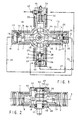
- the compressor has four cylinders 1, 2, 3 and 4, of which cylinders 1 and 2 have a common cylinder axis 5 lying in the plane of the drawing in FIG. 1 and cylinders 3 and 4 also have a common axis 6 which is set back somewhat with respect to the drawing plane of FIG. 1.
- a piston 7 is mounted in the cylinder 1 and is connected via a piston rod 8 to a yoke 9, which transmits the driving force from a crank pin 10 to the piston 7 via an eccentric disk 11.
- a piston 12, which is movably mounted in a cylinder insert 14 of the cylinder 2, is also connected to the yoke 9 via a piston rod 13.
- the compression space 15 of the cylinder 1 forming the first compression stage, which is the smallest in the position of the piston 7 shown in FIG.
- a suction valve 18 is provided in the piston 7, which, during the suction stroke of the piston 7, connects the compression space 15 to the side of the piston facing away from this space.
- the cylinder 1 is provided with a cylinder cover 19 which is detachably fastened to it and to which a line 20 shown in broken lines is connected is, which leads the gas compressed to 5 bar in the compression chamber 15 to the next compression stage in the cylinder 2.
- the piston 12 of the second compression stage is in its bottom dead center in the position shown in FIG. 1, so that the compression space 21 is the largest.
- the compression space 21 is delimited at the end by a plate 22 which has two openings, to which a suction valve 23 and a pressure valve 24 are assigned.
- the cylinder insert 14 and the plate 22 are held by a cylinder cover 25 which is detachably attached to the cylinder 2. From the cylinder cover 25 leads a line 26 shown in dash-dotted lines that in the compression space 21 to e.g. 19 bar compressed gas to the third compression stage in cylinder 3.
- This cylinder is also provided with a cylinder insert 27, in which a piston 28 is slidably mounted, which is attached with its piston rod 29 to a second yoke 30.
- an eccentric disc 31 (FIG. 2) slides, which forms a piece with the eccentric disc 11 in the yoke 9 and is also rotatably mounted on the crank pin 10.
- the two eccentric discs 11 and 31 are offset from one another by an angle of 180 °.
- a piston 32 which is mounted in a cylinder insert 33 in the cylinder 4, is fastened to the yoke 30, opposite the piston 28.
- the cylinder insert 33 here also forms the cylinder cover, in which there is a compression space 34, a suction valve (not shown) and a pressure valve 35.
- the cylinder insert 27 in the cylinder 3 delimits a compression space 37 in the same way as the cylinder insert 14 of the second compression stage together with a plate 36 and is together with the plate 36 from a detachably attached cylinder cover 38 is held in cylinder 3.
- the plate 36 has two openings, in the area of which a suction valve 39 and a pressure valve 40 are arranged. From the cylinder cover 38, a line 41 drawn in broken lines leads the gas compressed in the third compression stage to 60 bar, for example, to the fourth compression stage in the cylinder 4. The gas compressed here to the final pressure of 180 bar, for example, leaves the compressor via a line 42 connected to the cylinder insert 33.
- crank pin 10 As shown in FIG. 2, two counterweights 43 rotating with it are attached to the crank pin 10.
- the crank pin 10 merges into a stub shaft 45 which is connected to an electric motor 47 via a coupling piece 46 (FIG. 3).
- the stub shaft 45 is mounted in a bearing cover 48 which is detachably fastened in the housing 44.
- the free end of the crank pin 10 is supported via a sleeve 50, which carries the upper counterweight 43 in FIG. 2, in a bearing cover 49 which, like the bearing cover 48, is attached in the housing 44.
- a connection bore 65 is provided on the housing 44 between the cylinders 2 and 3, through which the gas to be compressed is drawn in from a source (not shown) at a pressure of, for example, 1 bar.
- This gas flows through the housing 44 and the cylinder 1, for which purpose a connecting channel, not shown, is provided in the piston guide piece 8a of the piston 7. From the piston side facing away from the compression chamber 15, the gas then passes through the suction valve 18 during the suction stroke of the Piston 7 in the compression space 15. It is also possible to make the connection bore 65 directly on the cylinder, specifically on the underside of the piston in the region of the end of the suction stroke of the piston 7.
- the electric drive motor 47 is arranged below the compressor, the cylinders 1 to 4 of which lie in two essentially horizontal planes.
- the compressor is fastened together with the electric motor 47 to a support frame 51 which surrounds the electric motor on three sides and is fastened to the floor by means of four rubber bearings 52.
- An electrically driven fan 53 is also fastened to the support frame 51, which draws in ambient air and directs it downward via a channel formed in the support frame 51 into a space 54 below the electric motor 47.
- the connecting lines 20, 26 and 41 are guided into this space 54 in order to cool the gas to be conducted in them from one compression stage to the next compression stage.
- An electrical switch box 55 is provided between the fan 53 and the room 54, but is located outside the air duct.
- a hood 56 which is divided into a lower part and an upper part.
- the two parts overlap somewhat at half height.
- an air filter 57 is provided between the two parts for the ambient air sucked in by the fan 53.
- the hood 56 forms a central collar 58, which is spanned by a cover 59, an air filter 60 being provided between the collar and the cover.
- the cooling air flowing through the space 54 emerges via this air filter 60 after it has risen next to the electric motor 47 and has cooled around the compressor.
- an eyelet 62 can be screwed in, which serves to receive a load hook.
- the 4 is a slider 63 in the form of a square provided for driving the yokes 9 and 30 - instead of a slider with two eccentric discs.
- the square 63 has two parallel sides, horizontal in FIG. 4, which slide in a horizontal longitudinal slot 64 in the yoke 9. The extension of the longitudinal slot 64 is thus transverse to the direction of movement of the pistons 7 and 12.
- the two parallel sides of the square 63 which are vertical in FIG. 4, are movable in a longitudinal slot of the yoke 30, the longitudinal extension of which is vertical, that is again transverse to Movement of the pistons 28 and 32.
- Rolling elements can be arranged between the sliding surfaces of the cant 63 and the longitudinal slots, for example in the form of needles. Such rolling elements can also be arranged between the crank pin 10 extending through the square piece and the surrounding bore in the square 63.
- 66 denotes the high-pressure collector for the compressed natural gas, while a pressure switch 67 is provided for switching the electric motor 47 on and off.
Landscapes
- Engineering & Computer Science (AREA)
- Mechanical Engineering (AREA)
- General Engineering & Computer Science (AREA)
- Compressors, Vaccum Pumps And Other Relevant Systems (AREA)
- Compressor (AREA)
Applications Claiming Priority (2)
| Application Number | Priority Date | Filing Date | Title |
|---|---|---|---|
| CH4560/86 | 1986-11-14 | ||
| CH456086A CH671610A5 (fr) | 1986-11-14 | 1986-11-14 |
Publications (2)
| Publication Number | Publication Date |
|---|---|
| EP0269882A2 true EP0269882A2 (fr) | 1988-06-08 |
| EP0269882A3 EP0269882A3 (fr) | 1988-07-06 |
Family
ID=4278355
Family Applications (1)
| Application Number | Title | Priority Date | Filing Date |
|---|---|---|---|
| EP87116060A Withdrawn EP0269882A3 (fr) | 1986-11-14 | 1987-10-31 | Compresseur à pistons stationnaire pour comprimer le gaz naturel |
Country Status (4)
| Country | Link |
|---|---|
| EP (1) | EP0269882A3 (fr) |
| AU (1) | AU599768B2 (fr) |
| CA (1) | CA1301724C (fr) |
| CH (1) | CH671610A5 (fr) |
Cited By (15)
| Publication number | Priority date | Publication date | Assignee | Title |
|---|---|---|---|---|
| EP0378967A1 (fr) * | 1989-01-19 | 1990-07-25 | GebràDer Sulzer Aktiengesellschaft | Compresseur à piston |
| AU599768B2 (en) * | 1986-11-14 | 1990-07-26 | Greenfield Ag | A stationary reciprocating compressor for compressing natural gas |
| AU625116B2 (en) * | 1989-03-23 | 1992-07-02 | Greenfield Ag | Reciprocating compressor |
| EP0878659A3 (fr) * | 1997-05-13 | 1999-05-26 | SAFE S.r.l. | Système pour la distribution de gaz sous pression |
| US6283723B1 (en) * | 1997-01-27 | 2001-09-04 | Vairex Corporation | Integrated compressor expander apparatus |
| EP1310673A1 (fr) * | 1999-09-09 | 2003-05-14 | Sanyo Electric Co., Ltd. | Compresseur à haute pression à plusieurs étages |
| EP1176309A3 (fr) * | 2000-07-28 | 2003-08-06 | SANYO ELECTRIC Co., Ltd. | Compresseur à pistons |
| US6653004B1 (en) | 1999-10-12 | 2003-11-25 | Jeffrey Lewis Barber | Process control for multiple air supplies |
| CN101672264B (zh) * | 2009-09-30 | 2011-10-19 | 浙江鸿友压缩机制造有限公司 | 直线往复活塞式压缩机 |
| US20140238327A1 (en) * | 2013-02-27 | 2014-08-28 | State of Oregon acting by and through the State Board of Higher Education on behalf of Oregon | Internal combustion engine for natural gas compressor operation |
| EP2495395A4 (fr) * | 2009-10-26 | 2014-10-22 | Yugen Kaisha K R And D | Dispositif de cylindre rotatif |
| US9528465B2 (en) | 2014-04-02 | 2016-12-27 | Oregon State University | Internal combustion engine for natural gas compressor operation |
| CN108591009A (zh) * | 2017-03-23 | 2018-09-28 | 中清能(北京)科技有限公司 | 一种活塞式空压机、运动转换机构及车用空压机 |
| CN109322810A (zh) * | 2018-11-28 | 2019-02-12 | 浙江盛源空压机制造有限公司 | 一种星型空压机 |
| EP3486485A1 (fr) * | 2017-11-20 | 2019-05-22 | Kabushiki Kaisha Kobe Seiko Sho (Kobe Steel, Ltd.) | Compresseur |
Families Citing this family (3)
| Publication number | Priority date | Publication date | Assignee | Title |
|---|---|---|---|---|
| CN103437973B (zh) * | 2013-09-18 | 2015-12-30 | 安徽华晶机械股份有限公司 | 立式星型高压空压机 |
| CN103452798A (zh) * | 2013-09-18 | 2013-12-18 | 安徽华晶机械股份有限公司 | 立式星型高压空压机的传动装置 |
| US11913441B2 (en) * | 2021-12-29 | 2024-02-27 | Transportation Ip Holdings, Llc | Air compressor system having a hollow piston forming an interior space and a check valve in a piston crown allowing air to exit the interior space |
Family Cites Families (10)
| Publication number | Priority date | Publication date | Assignee | Title |
|---|---|---|---|---|
| FR485398A (fr) * | 1917-05-09 | 1918-01-04 | Paul Schou | Pompe |
| FR837768A (fr) * | 1938-01-25 | 1939-02-20 | Compresseur pour la production de l'air comprimé de service sur les aéroplanes et appareils analogues | |
| US2517367A (en) * | 1946-09-24 | 1950-08-01 | Winkler Margenthaler Inc | Gas compressor |
| GB752546A (en) * | 1954-03-01 | 1956-07-11 | Specialties Dev Corp | Improvements in multi-stage reciprocating compressors |
| US3587406A (en) * | 1968-07-26 | 1971-06-28 | Copeland Refrigeration Corp | Compressor |
| DE2545998A1 (de) * | 1974-10-15 | 1976-04-29 | Notario Luis Iturriaga | Compressor mit wechsellaeufigen kolben |
| DE2454956A1 (de) * | 1974-11-20 | 1976-05-26 | Zlof Dieter Dipl Betriebsw | Mehrstufiger hubkolbenkompressor |
| JPS5823032Y2 (ja) * | 1979-11-08 | 1983-05-17 | 武蔵精密工業株式会社 | 水平対向型圧縮機 |
| AU524681B2 (en) * | 1980-07-24 | 1982-09-30 | Tecumseh Products Company | Split crankcase radial compressor |
| CH671610A5 (fr) * | 1986-11-14 | 1989-09-15 | Sulzer Ag |
-
1986
- 1986-11-14 CH CH456086A patent/CH671610A5/de not_active IP Right Cessation
-
1987
- 1987-10-23 CA CA000550041A patent/CA1301724C/fr not_active Expired - Lifetime
- 1987-10-31 EP EP87116060A patent/EP0269882A3/fr not_active Withdrawn
-
1988
- 1988-03-25 AU AU13739/88A patent/AU599768B2/en not_active Expired
Cited By (21)
| Publication number | Priority date | Publication date | Assignee | Title |
|---|---|---|---|---|
| AU599768B2 (en) * | 1986-11-14 | 1990-07-26 | Greenfield Ag | A stationary reciprocating compressor for compressing natural gas |
| US5033940A (en) * | 1989-01-19 | 1991-07-23 | Sulzer Brothers Limited | Reciprocating high-pressure compressor piston with annular clearance |
| EP0378967A1 (fr) * | 1989-01-19 | 1990-07-25 | GebràDer Sulzer Aktiengesellschaft | Compresseur à piston |
| AU625116B2 (en) * | 1989-03-23 | 1992-07-02 | Greenfield Ag | Reciprocating compressor |
| US6283723B1 (en) * | 1997-01-27 | 2001-09-04 | Vairex Corporation | Integrated compressor expander apparatus |
| EP0878659A3 (fr) * | 1997-05-13 | 1999-05-26 | SAFE S.r.l. | Système pour la distribution de gaz sous pression |
| EP1310673A1 (fr) * | 1999-09-09 | 2003-05-14 | Sanyo Electric Co., Ltd. | Compresseur à haute pression à plusieurs étages |
| US6653004B1 (en) | 1999-10-12 | 2003-11-25 | Jeffrey Lewis Barber | Process control for multiple air supplies |
| US6692239B2 (en) | 2000-07-28 | 2004-02-17 | Sanyo Electric Co., Ltd. | Reciprocating compressor |
| US6666657B2 (en) | 2000-07-28 | 2003-12-23 | Sanyo Electric Co., Ltd. | Reciprocating parallel flow compressor with discharge muffler |
| EP1176309A3 (fr) * | 2000-07-28 | 2003-08-06 | SANYO ELECTRIC Co., Ltd. | Compresseur à pistons |
| CN101672264B (zh) * | 2009-09-30 | 2011-10-19 | 浙江鸿友压缩机制造有限公司 | 直线往复活塞式压缩机 |
| EP2495395A4 (fr) * | 2009-10-26 | 2014-10-22 | Yugen Kaisha K R And D | Dispositif de cylindre rotatif |
| TWI496990B (zh) * | 2009-10-26 | 2015-08-21 | Yugen Kaisha K R & D | 回轉式汽缸裝置 |
| US20140238327A1 (en) * | 2013-02-27 | 2014-08-28 | State of Oregon acting by and through the State Board of Higher Education on behalf of Oregon | Internal combustion engine for natural gas compressor operation |
| US9316178B2 (en) * | 2013-02-27 | 2016-04-19 | State Of Oregon Acting By And Through The State Board Of Higher Education On Behalf Of Oregon State University | Internal combustion engine for natural gas compressor operation |
| US9528465B2 (en) | 2014-04-02 | 2016-12-27 | Oregon State University | Internal combustion engine for natural gas compressor operation |
| CN108591009A (zh) * | 2017-03-23 | 2018-09-28 | 中清能(北京)科技有限公司 | 一种活塞式空压机、运动转换机构及车用空压机 |
| EP3486485A1 (fr) * | 2017-11-20 | 2019-05-22 | Kabushiki Kaisha Kobe Seiko Sho (Kobe Steel, Ltd.) | Compresseur |
| CN109812395A (zh) * | 2017-11-20 | 2019-05-28 | 株式会社神户制钢所 | 压缩机 |
| CN109322810A (zh) * | 2018-11-28 | 2019-02-12 | 浙江盛源空压机制造有限公司 | 一种星型空压机 |
Also Published As
| Publication number | Publication date |
|---|---|
| CA1301724C (fr) | 1992-05-26 |
| CH671610A5 (fr) | 1989-09-15 |
| AU599768B2 (en) | 1990-07-26 |
| AU1373988A (en) | 1989-09-28 |
| EP0269882A3 (fr) | 1988-07-06 |
Similar Documents
| Publication | Publication Date | Title |
|---|---|---|
| EP0269882A2 (fr) | Compresseur à pistons stationnaire pour comprimer le gaz naturel | |
| EP1031727B1 (fr) | Système de refroidissement pour un compresseur à piston | |
| EP0725897B1 (fr) | Compresseur a piston pour milieux gazeux | |
| DE112019002266T5 (de) | Klimaanlage für ein fahrzeug | |
| DE2619561A1 (de) | Kolbenverdichter | |
| DE3120190A1 (de) | Hubkolben-kurbelwellen-brennkraftmaschine | |
| DE2555140A1 (de) | Flotationskammer-maschine | |
| DE4219462A1 (de) | Hydraulik-Aggregat | |
| DE3340733A1 (de) | Kolbenverdichter | |
| EP1339591A1 (fr) | Agencement d'un compresseur a piston sec sur un vehicule | |
| DE19813624A1 (de) | Luftgekühlter Verbrennungsmotor mit um eine vertikale Achse rotierender Kurbelwelle, insbesondere Einzylinder-Dieselmotor | |
| DE1503401A1 (de) | Luftdichte Motorkompressoren | |
| DE29614589U1 (de) | Hubkolbenmaschine mit veränderbar einstellbarem Massenausgleich | |
| DE2659282A1 (de) | Kraftfahrzeug mit einer brennkraftmaschine | |
| EP0560203A1 (fr) | Support de vilebrequin pour moteur à combustion deux-temps avec étanchéité de carter de vilebrequin | |
| DD147787A3 (de) | Hubkolbenverdichter-anlage | |
| DE671236C (de) | Kuehlanlage fuer die Kuehlfluessigkeit von Brennkraftmaschinen in Fahrzeugen | |
| DE3109778A1 (de) | Hubkolben-maschine | |
| DE2534610A1 (de) | Verfahren zur steuerung des betriebes eines zweigeschwindigkeits-elektromotors | |
| WO2002018788A1 (fr) | Compresseur a pistons avec compensation dynamique des masses au niveau des transmissions a manivelles | |
| DE3512961A1 (de) | Schraubenverdichter in kompaktausfuehrung | |
| DE69712897T2 (de) | Bus mit klimaanlage | |
| WO2002018787A1 (fr) | Compresseur a piston comprenant un vilebrequin a equilibrage dynamique des masses, notamment destine aux vehicules sur rails (masse d'equilibrage amovible) | |
| EP1181230B1 (fr) | Ascenseur hydraulique | |
| DE2626860A1 (de) | Kolbenverdichter fuer eine anlage zur kaelteerzeugung |
Legal Events
| Date | Code | Title | Description |
|---|---|---|---|
| PUAI | Public reference made under article 153(3) epc to a published international application that has entered the european phase |
Free format text: ORIGINAL CODE: 0009012 |
|
| PUAL | Search report despatched |
Free format text: ORIGINAL CODE: 0009013 |
|
| AK | Designated contracting states |
Kind code of ref document: A2 Designated state(s): AT DE GB IT |
|
| AK | Designated contracting states |
Kind code of ref document: A3 Designated state(s): AT DE GB IT |
|
| 17P | Request for examination filed |
Effective date: 19881221 |
|
| 17Q | First examination report despatched |
Effective date: 19890703 |
|
| STAA | Information on the status of an ep patent application or granted ep patent |
Free format text: STATUS: THE APPLICATION IS DEEMED TO BE WITHDRAWN |
|
| 18D | Application deemed to be withdrawn |
Effective date: 19901227 |
|
| RIN1 | Information on inventor provided before grant (corrected) |
Inventor name: BAUMANN, HEINZ |