EP0269898A2 - Appareil pour délivrer un courant pulsé - Google Patents
Appareil pour délivrer un courant pulsé Download PDFInfo
- Publication number
- EP0269898A2 EP0269898A2 EP87116235A EP87116235A EP0269898A2 EP 0269898 A2 EP0269898 A2 EP 0269898A2 EP 87116235 A EP87116235 A EP 87116235A EP 87116235 A EP87116235 A EP 87116235A EP 0269898 A2 EP0269898 A2 EP 0269898A2
- Authority
- EP
- European Patent Office
- Prior art keywords
- tube
- raceway
- pump
- clamp
- pulsatile
- Prior art date
- Legal status (The legal status is an assumption and is not a legal conclusion. Google has not performed a legal analysis and makes no representation as to the accuracy of the status listed.)
- Withdrawn
Links
Images








Classifications
-
- A—HUMAN NECESSITIES
- A61—MEDICAL OR VETERINARY SCIENCE; HYGIENE
- A61M—DEVICES FOR INTRODUCING MEDIA INTO, OR ONTO, THE BODY; DEVICES FOR TRANSDUCING BODY MEDIA OR FOR TAKING MEDIA FROM THE BODY; DEVICES FOR PRODUCING OR ENDING SLEEP OR STUPOR
- A61M60/00—Blood pumps; Devices for mechanical circulatory actuation; Balloon pumps for circulatory assistance
- A61M60/50—Details relating to control
- A61M60/508—Electronic control means, e.g. for feedback regulation
- A61M60/562—Electronic control means, e.g. for feedback regulation for making blood flow pulsatile in blood pumps that do not intrinsically create pulsatile flow
-
- A—HUMAN NECESSITIES
- A61—MEDICAL OR VETERINARY SCIENCE; HYGIENE
- A61M—DEVICES FOR INTRODUCING MEDIA INTO, OR ONTO, THE BODY; DEVICES FOR TRANSDUCING BODY MEDIA OR FOR TAKING MEDIA FROM THE BODY; DEVICES FOR PRODUCING OR ENDING SLEEP OR STUPOR
- A61M60/00—Blood pumps; Devices for mechanical circulatory actuation; Balloon pumps for circulatory assistance
- A61M60/10—Location thereof with respect to the patient's body
- A61M60/104—Extracorporeal pumps, i.e. the blood being pumped outside the patient's body
- A61M60/109—Extracorporeal pumps, i.e. the blood being pumped outside the patient's body incorporated within extracorporeal blood circuits or systems
- A61M60/113—Extracorporeal pumps, i.e. the blood being pumped outside the patient's body incorporated within extracorporeal blood circuits or systems in other functional devices, e.g. dialysers or heart-lung machines
-
- A—HUMAN NECESSITIES
- A61—MEDICAL OR VETERINARY SCIENCE; HYGIENE
- A61M—DEVICES FOR INTRODUCING MEDIA INTO, OR ONTO, THE BODY; DEVICES FOR TRANSDUCING BODY MEDIA OR FOR TAKING MEDIA FROM THE BODY; DEVICES FOR PRODUCING OR ENDING SLEEP OR STUPOR
- A61M60/00—Blood pumps; Devices for mechanical circulatory actuation; Balloon pumps for circulatory assistance
- A61M60/20—Type thereof
- A61M60/205—Non-positive displacement blood pumps
- A61M60/216—Non-positive displacement blood pumps including a rotating member acting on the blood, e.g. impeller
- A61M60/226—Non-positive displacement blood pumps including a rotating member acting on the blood, e.g. impeller the blood flow through the rotating member having mainly radial components
- A61M60/232—Centrifugal pumps
-
- A—HUMAN NECESSITIES
- A61—MEDICAL OR VETERINARY SCIENCE; HYGIENE
- A61M—DEVICES FOR INTRODUCING MEDIA INTO, OR ONTO, THE BODY; DEVICES FOR TRANSDUCING BODY MEDIA OR FOR TAKING MEDIA FROM THE BODY; DEVICES FOR PRODUCING OR ENDING SLEEP OR STUPOR
- A61M60/00—Blood pumps; Devices for mechanical circulatory actuation; Balloon pumps for circulatory assistance
- A61M60/20—Type thereof
- A61M60/247—Positive displacement blood pumps
- A61M60/253—Positive displacement blood pumps including a displacement member directly acting on the blood
- A61M60/268—Positive displacement blood pumps including a displacement member directly acting on the blood the displacement member being flexible, e.g. membranes, diaphragms or bladders
- A61M60/279—Peristaltic pumps, e.g. roller pumps
-
- A—HUMAN NECESSITIES
- A61—MEDICAL OR VETERINARY SCIENCE; HYGIENE
- A61M—DEVICES FOR INTRODUCING MEDIA INTO, OR ONTO, THE BODY; DEVICES FOR TRANSDUCING BODY MEDIA OR FOR TAKING MEDIA FROM THE BODY; DEVICES FOR PRODUCING OR ENDING SLEEP OR STUPOR
- A61M60/00—Blood pumps; Devices for mechanical circulatory actuation; Balloon pumps for circulatory assistance
- A61M60/30—Medical purposes thereof other than the enhancement of the cardiac output
- A61M60/36—Medical purposes thereof other than the enhancement of the cardiac output for specific blood treatment; for specific therapy
- A61M60/38—Blood oxygenation
-
- A—HUMAN NECESSITIES
- A61—MEDICAL OR VETERINARY SCIENCE; HYGIENE
- A61M—DEVICES FOR INTRODUCING MEDIA INTO, OR ONTO, THE BODY; DEVICES FOR TRANSDUCING BODY MEDIA OR FOR TAKING MEDIA FROM THE BODY; DEVICES FOR PRODUCING OR ENDING SLEEP OR STUPOR
- A61M60/00—Blood pumps; Devices for mechanical circulatory actuation; Balloon pumps for circulatory assistance
- A61M60/40—Details relating to driving
- A61M60/424—Details relating to driving for positive displacement blood pumps
- A61M60/438—Details relating to driving for positive displacement blood pumps the force acting on the blood contacting member being mechanical
- A61M60/441—Details relating to driving for positive displacement blood pumps the force acting on the blood contacting member being mechanical generated by an electromotor
- A61M60/443—Details relating to driving for positive displacement blood pumps the force acting on the blood contacting member being mechanical generated by an electromotor with means converting the rotation into a translational movement of the displacement member
-
- A—HUMAN NECESSITIES
- A61—MEDICAL OR VETERINARY SCIENCE; HYGIENE
- A61M—DEVICES FOR INTRODUCING MEDIA INTO, OR ONTO, THE BODY; DEVICES FOR TRANSDUCING BODY MEDIA OR FOR TAKING MEDIA FROM THE BODY; DEVICES FOR PRODUCING OR ENDING SLEEP OR STUPOR
- A61M60/00—Blood pumps; Devices for mechanical circulatory actuation; Balloon pumps for circulatory assistance
- A61M60/50—Details relating to control
- A61M60/508—Electronic control means, e.g. for feedback regulation
- A61M60/515—Regulation using real-time patient data
-
- A—HUMAN NECESSITIES
- A61—MEDICAL OR VETERINARY SCIENCE; HYGIENE
- A61M—DEVICES FOR INTRODUCING MEDIA INTO, OR ONTO, THE BODY; DEVICES FOR TRANSDUCING BODY MEDIA OR FOR TAKING MEDIA FROM THE BODY; DEVICES FOR PRODUCING OR ENDING SLEEP OR STUPOR
- A61M60/00—Blood pumps; Devices for mechanical circulatory actuation; Balloon pumps for circulatory assistance
- A61M60/50—Details relating to control
- A61M60/508—Electronic control means, e.g. for feedback regulation
- A61M60/538—Regulation using real-time blood pump operational parameter data, e.g. motor current
-
- A—HUMAN NECESSITIES
- A61—MEDICAL OR VETERINARY SCIENCE; HYGIENE
- A61M—DEVICES FOR INTRODUCING MEDIA INTO, OR ONTO, THE BODY; DEVICES FOR TRANSDUCING BODY MEDIA OR FOR TAKING MEDIA FROM THE BODY; DEVICES FOR PRODUCING OR ENDING SLEEP OR STUPOR
- A61M60/00—Blood pumps; Devices for mechanical circulatory actuation; Balloon pumps for circulatory assistance
- A61M60/50—Details relating to control
- A61M60/508—Electronic control means, e.g. for feedback regulation
- A61M60/538—Regulation using real-time blood pump operational parameter data, e.g. motor current
- A61M60/546—Regulation using real-time blood pump operational parameter data, e.g. motor current of blood flow, e.g. by adapting rotor speed
-
- A—HUMAN NECESSITIES
- A61—MEDICAL OR VETERINARY SCIENCE; HYGIENE
- A61M—DEVICES FOR INTRODUCING MEDIA INTO, OR ONTO, THE BODY; DEVICES FOR TRANSDUCING BODY MEDIA OR FOR TAKING MEDIA FROM THE BODY; DEVICES FOR PRODUCING OR ENDING SLEEP OR STUPOR
- A61M60/00—Blood pumps; Devices for mechanical circulatory actuation; Balloon pumps for circulatory assistance
- A61M60/50—Details relating to control
- A61M60/508—Electronic control means, e.g. for feedback regulation
- A61M60/538—Regulation using real-time blood pump operational parameter data, e.g. motor current
- A61M60/554—Regulation using real-time blood pump operational parameter data, e.g. motor current of blood pressure
-
- A—HUMAN NECESSITIES
- A61—MEDICAL OR VETERINARY SCIENCE; HYGIENE
- A61M—DEVICES FOR INTRODUCING MEDIA INTO, OR ONTO, THE BODY; DEVICES FOR TRANSDUCING BODY MEDIA OR FOR TAKING MEDIA FROM THE BODY; DEVICES FOR PRODUCING OR ENDING SLEEP OR STUPOR
- A61M60/00—Blood pumps; Devices for mechanical circulatory actuation; Balloon pumps for circulatory assistance
- A61M60/50—Details relating to control
- A61M60/585—User interfaces
-
- A—HUMAN NECESSITIES
- A61—MEDICAL OR VETERINARY SCIENCE; HYGIENE
- A61M—DEVICES FOR INTRODUCING MEDIA INTO, OR ONTO, THE BODY; DEVICES FOR TRANSDUCING BODY MEDIA OR FOR TAKING MEDIA FROM THE BODY; DEVICES FOR PRODUCING OR ENDING SLEEP OR STUPOR
- A61M60/00—Blood pumps; Devices for mechanical circulatory actuation; Balloon pumps for circulatory assistance
- A61M60/80—Constructional details other than related to driving
- A61M60/845—Constructional details other than related to driving of extracorporeal blood pumps
- A61M60/851—Valves
- A61M60/853—Valves the valve being formed by a flexible tube element which is clamped for restricting the flow
-
- A—HUMAN NECESSITIES
- A61—MEDICAL OR VETERINARY SCIENCE; HYGIENE
- A61M—DEVICES FOR INTRODUCING MEDIA INTO, OR ONTO, THE BODY; DEVICES FOR TRANSDUCING BODY MEDIA OR FOR TAKING MEDIA FROM THE BODY; DEVICES FOR PRODUCING OR ENDING SLEEP OR STUPOR
- A61M2205/00—General characteristics of the apparatus
- A61M2205/33—Controlling, regulating or measuring
-
- A—HUMAN NECESSITIES
- A61—MEDICAL OR VETERINARY SCIENCE; HYGIENE
- A61M—DEVICES FOR INTRODUCING MEDIA INTO, OR ONTO, THE BODY; DEVICES FOR TRANSDUCING BODY MEDIA OR FOR TAKING MEDIA FROM THE BODY; DEVICES FOR PRODUCING OR ENDING SLEEP OR STUPOR
- A61M2205/00—General characteristics of the apparatus
- A61M2205/33—Controlling, regulating or measuring
- A61M2205/3303—Using a biosensor
-
- A—HUMAN NECESSITIES
- A61—MEDICAL OR VETERINARY SCIENCE; HYGIENE
- A61M—DEVICES FOR INTRODUCING MEDIA INTO, OR ONTO, THE BODY; DEVICES FOR TRANSDUCING BODY MEDIA OR FOR TAKING MEDIA FROM THE BODY; DEVICES FOR PRODUCING OR ENDING SLEEP OR STUPOR
- A61M2230/00—Measuring parameters of the user
- A61M2230/04—Heartbeat characteristics, e.g. ECG, blood pressure modulation
-
- A—HUMAN NECESSITIES
- A61—MEDICAL OR VETERINARY SCIENCE; HYGIENE
- A61M—DEVICES FOR INTRODUCING MEDIA INTO, OR ONTO, THE BODY; DEVICES FOR TRANSDUCING BODY MEDIA OR FOR TAKING MEDIA FROM THE BODY; DEVICES FOR PRODUCING OR ENDING SLEEP OR STUPOR
- A61M60/00—Blood pumps; Devices for mechanical circulatory actuation; Balloon pumps for circulatory assistance
- A61M60/80—Constructional details other than related to driving
- A61M60/855—Constructional details other than related to driving of implantable pumps or pumping devices
- A61M60/89—Valves
- A61M60/892—Active valves, i.e. actuated by an external force
Definitions
- This invention relates to a pulsatile flow delivery apparatus which can produce an arterial pulsatile pressure wave form close to that produced by the natural heart.
- a pulsatile roller pump as shown in Figure 1 has been used for extracorporeal circulation during either cardiopulmonary bypass or extended cardiac support or assistance.
- the pump is based on the principle of intermittently switching on and off the rotation of an arm 3 bearing two or three milking rollers 3a moving inside a horse shoe shaped raceway 1 that holds a tube 2, thus milking the blood (or any fluid) intermittently, i.e., in a pulsatile fashion.
- the speed of rotation is set so as to obtain the desired minute output at the set pulse frequency.
- the currently available pulsatile pump has three main shortcomings whose solution are desirable.
- the pulse wave of the pulsatile roller pump is the resultant of the summation of the sequential milking of each of the rotating two (or three) rollers, thus the pulse wave contour is scalloped or indented.
- the velocity of pressure change or ascent slope of the pressure wave (dp/dt) is relatively slow with a relatively narrow pulse pressure and far from the natural cardiac beat pulse wave contour.
- the intended pulsatile flow becomes almost a constant flow type perfusion, i.e., the pump can not follow high frequency pulse rates.
- This invention is therefore aimed at solving the above-mentioned shortcomings to provide a simple, economic and reliable pulsatile flow delivery apparatus which can produce an arterial pulsatile pressure wave form very close to that produced by the natural heart.
- a pulsatile flow delivery apparatus comprising a pump means for producing a continuous flow of fluid; an elastic tube having an inlet and an outlet and connected at the inlet to the pump means for flowing the fluid therethrough, at least a part of the tube being made of a material with a rubber hardness code of no greater than 70° (Japanese Industrial Standard K 6301 A testing); an occlusive clamp means placed on the outlet of the tube for opening and closing the outlet of the tube; and control means connected to the clamp means for controlling the timing for opening and closing of the clamp means to thereby convert the flow of the fluid flown from the tube into a pulsatile flow.
- a pulsatile flow delivery apparatus comprising a horse shoe shaped raceway having an inner side of a prescribed curvature; a tube for flowing a fluid therethrough, the tube having a pump head portion disposed along the inner side of the raceway, the tube being made of a material with a rubber hardness code of no greater than 70° (Japanese Industrial Standard K 6301 A testing); a milking mechanism comprising a pivot shaft, a rotating arm fixedly secured to the shaft and a milking roller rotatably mounted on one end of the rotating arm, the milking means being disposed so that, as the rotating arm rotates, the milking roller travels along the inner side of the raceway to squeeze the pump head portion of the tube against the raceway, to thereby milk the pump head portion intermittently as the rotating arm rotates; an occlusive clamp means for opening and closing a portion of the tube downstream the pump head portion; and control means connected to the clamp means for controlling the timing for opening and closing of the clamp means to
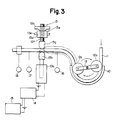
- FIG. 3 depicts a pulsatile flow delivery apparatus in accordance with this invention being provided in conjunction with a conventional two-roller pump but could be a three-roller pump or a centrifugal pump instead.
- the apparatus includes a horse shoe shaped raceway 10 which holds, within its inner curvature, a pump head tubing 11, and a rotating arm 12 carrying two milking rollers 12a at opposite ends thereof.
- the pump head tubing 11 is made out of a material with a rubber hardness code of ⁇ 70° (Japanese Industrial Standard) which will allow storage of the stroke volume at an adequate intraluminal pressure when the outlet is intermittently occluded while the two rotating rollers 12a continuously propel blood (or any fluid) by their milking effect on the pump head tubing.
- the outlet of this tube 11 is held by a clamp 13 located at a specific distance from the end of the raceway 10.
- the clamp 13 has one stationary component 13a and one mobile component 13b that is moved up and down by a solenoid 13c.
- the stationary component 13a is comprised of a nut member 13e fixedly secured to a base (not shown) through a bracket 13d, a screw 13f threaded into the nut member 13e and having an occlusiveness control knob 13g at its one end, and a fixing nut 13h threaded on the screw 13f for fixing the screw 13f in the determined position by the nut member 13e.
- This clamp 13 occludes the outlet of the tubing 11 intermittently and at properly timed sequence, usually sychronized to the patient's electrocardiographic signal, or to the patient's pace maker or to an intrinsic device's signal picked up by an electrocardiograph 15, properly amplified and processed by a synchronizer 14 which in turn sends the final command signals to the solenoid 13c.
- transducers 16 and 17 to measure intraluminal pressure of the tube compartment between the clamp and the pump, and downstream the clamp, respectively, as well as a flow measuring sensor 18 are used in this experimental prototype.
- the tube outlet clamp 13 actuated in a synchronized manner with the patient's electrocardiogram keeps the tube occluded during the patient's cardiac ejection, during which time the rollers 12a continue their milking effect and propelling of blood into the closed compartment of the compliant tube.
- the intraluminal pressure continues to rise until the occluding clamp 13 opens, commanded by the synchronizing components 14 and 15, following the cardiac ejection, i.e., during diastole of the patient's cardiac cycle.
- the pressurized blood rushes downstream suddenly, i.e., in a pulsatile fashion into the patient's cardiovascular system.
- the rollers 12a maintain a constant flow at a rate determined by the set pump revolutions. The timing of the pulse and the duration of it can be freely adjusted and controlled by the component 14, and immediately from the pump rate.
- Figure 4 is a recording obtained with the embodiment utilizing an intrinsic signal to drive the solenoid 13a of the clamp 13.
- the tracings of panel (a) on the left hand side are those obtained with the conventional two-roller pump operated in a non-pulsatile fashion; those on the panel (b) are tracings obtained with the same roller pump whose revolutions per minute are the same as in panel (a) but the pulsatile flow conversion device has been activated at a rate of 60 per minute.
- the tracing A was obtained via the pressure transducer 16 and illustrates the pressure change of the tube 11 compartment between the clamp 13 and the raceway 10; the tracing B was obtained via the pressure transducer 17 and illustrates the tube intraluminal pressure changes downstream the clamp 13; tracing C is the phasic flow recording, while D is the mean flow recording measured downstream the clamp 13.
- the tracing E is the dp/dt of pressure B and measures the rate of pressure changes in the tubing just downstream the clamp 13.
- the pulsatile flow conversion device in accordance with this invention is provided in conjunction with standard conventional two or three roller pumps or centrifugal pumps.
- the apparatus requires the use of the perfusion tube 11 made out of a compliant material having a rubber hardness code of ⁇ 70° (JIS) to allow compartmentalization of the apparatus and the creation of a pressurizing compartment between the outlet occluding clamp 13 and the pump head.
- JIS rubber hardness code
- the opening and closing of this clamp 13 mediated by the solenoid 13c is actuated by proper electronic synchronization to the patient's electrocardiogram, to a cardiac pacemaker or to an intrinsic pulse rate controlling mechanism.
- the continuous flow produced by the ordinary roller or centrifugal pump is intermittently stored for pressurization and released at a high pressure in a short time, thus converting the originally low pressure continuous flow into a more effective high pressure pulsatile flow.
- the created pulse wave contour is smooth and not scalloped, the pulse pressure is wider and with a higher dp/dt than those produced by the conventional pulsatile roller or pulsatile centrifugal pumps.
- the tube outlet occluding clamp 13 is a separate entity from the pump itself and is driven by the solenoid 13c, it lends itself to easy synchronization with the patient's cardiac electrical activity, thus allowing the delivery of the pulsatile flow at the desired timing in relation to the cardiac cycle of the patient.
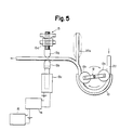
- FIG. 5 depicts the application of this pulsatile flow conversion device with still a different arrangement of the compliant tube compartment.
- the items in common with the previous arrangement are identified with the same numbers for simplification purposes.
- a commonly used somewhat rigid polyvinyl chloride tubing 20 has been used for the pump head.
- a compliant pouch 20a made out of a material with rubber hardness code of ⁇ 70° (JIS) and with specific dimensions to produce the best pressure - volume curves for the specific needs has been connected just downstream the raceway 10 of the pump before the occluding clamp 13.
- FIG. 6 shows a further modified pulsatile flow delivery apparatus in accordance with this invention.
- the apparatus includes a horse shoe shaped raceway 30 with an arc of 180° to 190°, which holds a pump head tubing 31.
- the pump head tubing 31 is made out of a somewhat compliant material with a rubber hardness code of ⁇ 70° (JIS), which avoids an excessive build up of the intraluminal pressure, and yet allows enough volume to be stored.
- a rotating arm 32 which holds a roller 32a at its one end and rotatable about a pivot shaft, is disposed adjacent to the raceway 30 for milking the tube 31.
- the outlet of the tube 31 is placed within an occluding clamp mechanism 33 for occluding or opening the outlet of the tubing for the predetermined time.
- the occlusiveness of the rotating roller 32a against the raceway 30 is controlled by an adjusting knob 32b which moves the roller closer to or away from the raceway 30.
- the rotating arm 32 is provided with two reflecting plates 34 and 35 at two different height levels, both held by the same axis of the rotating arm 32.
- the reflecting plate 34 is phased ⁇ 1 angle couterclockwise to the rotating arm 32
- the reflecting plate 35 is phased ⁇ 2 angle clockwise to the rotating arm 32. Both plates can be fixed at various ⁇ 1 and ⁇ 2 angles.
- Two light sources and light sensors, 36 and 37, to sense the reflected light by the reflecting plates are mounted on the top of the raceway 30, each set at the proper height to meet the corresponding reflecting plate.
- the inlet sensor 36 is located at the beginning of the raceway 10; the outlet sensor 37 is mounted at the exit side of the raceway.
- the inlet sensor 36 is set to meet the reflecting plate 34, and the outlet sensor 37 is at the height to meet the reflecting plate 35.
- Proximity magnetic sensors could be used in lieu of the light sensors.
- the sensor 36 senses the light beam reflected by the plate it sends a signal to the solenoid to open the clamping mechanism 33 of the outlet of the tube 31.
- the sensor 37 senses its reflected light beam on the plate 35, it sends a signal to the solenoid to close the clamping mechanism 13 of the outlet of the tube.
- the reflecting plates 34 and 35 as well as the sensors 36 and 37 make up the control mechanism of the clamp opening and closing the pump head tube outlet.
- the outlet of the pump head tube 31 is closed by the clamping mechanism 33.
- the rotating roller 32a starts its race on the raceway, and the milking effect on the pump head tube while the tube outlet is still closed.
- the intraluminal pressure of the tube increases as the rotating roller 32a races its way to the predetermined angle ⁇ 1, at which time the reflecting plate 34 is in front of the light source and sensor 36, thus the reflected beam is sensed by the sensor 36 which sends the signal to the solenoid to open the clamping mechanism 33 and the tube outlet is open. This results in a sudden flow of the pressurized contents of the tubing, in a pulsatile fashion, into the cardiovascular system of the patient.
- the sensor 37 picks up the reflected beam and sends the signal to the solenoid to close the clamping mechanism 33 on the outlet of the tubing.
- the timing of this closure is set so that the tube outlet is clamped just before the roller 32a leaves behind the raceway 30, which assures a non regurgitant flow within the tube 31.
- the rotating roller 32a continues its rotation off the raceway to the next cycle, during which time the pressure within the pump head tube 31 should be theoretically zero or whatever pressure exists in the inlet tubing.
- Figure 7 illustrates the pressure wave contour of a pilot experiment in a goat. To be noted is the close resemblance to the pressure wave produced by the natural heart. Furthermore the pressure wave tracing of Figure 7 was obtained at ⁇ 1 angle of 50°. By increasing the ⁇ 1 angle (pressurizing angle) to 80°, the rate of change of the upstroke slope, i.e., the dp/dt increases (Figure 8). These pressure characteristics are obtained because the physical properties of the pump head tubing (rubber hardness code of less than 70°) maintains the intraluminal pressure changes within a relatively narrow range with volume changes. Thus the peak pressures of both figures 7 and 8 experiments are close to 150 mmHg regardless of the ⁇ 1 angle, but the ascent slope is steeper in Figure 8.
- the sensors can be mounted on top of the raceway at the desired angle ⁇ 1 and ⁇ 2, thus requiring only one reflecting plate coaxial to the rotating arm 32. If the sensors are mounted on a holder that can be adjusted, the angles ⁇ 1 and ⁇ 2 can be varied even during rotation of the pump, i.e., without having to stop the pump.
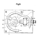
- FIG. 9 depicts a further modified pulsatile flow delivery apparatus in accordance with this invention.
- a rotating arm 40 holding a rotating roller 40a is attached at its axis of rotation to a cam 41 or command controller of the opening and closing a tube outlet clamp 42.
- a cam 41 or command controller of the opening and closing a tube outlet clamp 42 Opposing this cam 41, there is an occluding push rod 42a of the clamp that transmits and converts the circular motion of the cam 41 into a horizontal one.
- This occluding push rod 42a is kept in contact to the cam by a spring mechanism not illustrated in the figure.
- Opposing the free sided end of the occluding push rod 42a there is an occluder 42b of the clamp.
- the outlet of a pump head tube 31 is clamped between the occluding push rod 42a and the occluder 42b.
- the occluder 42b has a mechanism 42c for adjusting the tubing occlusiveness.
- the shape of the cam 41 as well as the angle at which the cam 41 is to actuate the push rod 42a in relation to the location of the rotating arm 40 within the raceway 30 are designed to provide a pressurizing angle ⁇ 1.
- the occluding push rod 42a keeps the clamp 42 closed for as long as the roller 40a is off the raceway 30 and for the pressurizing angle ⁇ 1 after the roller 40a has started its race on the raceway 30, at which point the cam 41 becomes operational, the occluding push rod 42a moves away from the occluder 42b and the clamp 42 opens.
- the cam 41 pushes back the push occluding rod 42a to the right of the Figure against the occluder 42b thus closing the clamp 42 controlling the outlet of the tubing 31.
- the occluding push rod 42a and the occluder 42b make up the components of the clamp 42, whose command controller is the cam 41.
- the pressure wave contour obtained by this cam driven clamp pulsatile pump is similar to that obtained by the solenoid clamp pump illustrated in Figure 6.
- the slope of the pressure change dp/dt as well as duration of the pulse can be modified to produce the best pressure wave contour for the patient.
- An alternative to using a horizontal cam mounted on the same axis of the rotating roller arm to convert the circular motion into a horizontal motion is to use a corrugated belt to transmit the rotation of the main axis to a separate vertical cam, so that the push rod 42a moves up and down instead of horizontally, thus converting the rotational motion of the axis of the main pump axis into a vertical one.
- the embodiments illustrated in Figures 6 and 9 are based on the interaction of two factors: the well known continuous flow pump function of the milking roller on one hand, and the compliance characteristics of the milked tube that enables storing pressure on the other.
- the embodiments of Figures 6 and 9 to minimize unnecessary and potentially undesirable excessive build up of pressure during the time flow is interrupted to convert the continuous flow of standard two or three roller pumps into a pulsatile pump, only one rotating milking roller is provided. Since the horse shoe shaped raceway has an arc of 180° to 190°, a check valve mechanism must be incorporated in the form of a tube clamp on the outlet of the pump head tubing.
- the stored pressure in the tube before the clamp opens as well as the duration of the ejection in relation to the cycle of the pump can be adjusted to produce the best pulsatile characteristics of the pressure wave.
- the stroke volume, or volume ejected in each cycle, is determined by the capacity of the milked pump head tube sustained by the arc of the raceway that comes in contact with the rotating milking roller before the outlet clamp closes. Since each pulse is produced by one single revolution or cycle of the pump, the resulting pulsatile pressure wave contour is sharp and not scalloped as that produced by the existing two or three roller pumps.
- pressure can be stored before the actual flow starts, by controlling the opening time of the clamp, i.e., ⁇ 1 angle, adequate pulse pressures as well as a relatively steep ascent slope of the pressure wave dp/dt can be obtained and adjusted to each patient's condition to produce the pulsatile characteristics that resembles the patient's natural heart the most.
- the pump is only one half of the total cardiopulmonary bypass set, the other half is the artificial lung or oxygenator.
- Current commercially available oxygenators were all designed to be used in conjunction with continuous flow pumps, roller or centrifugal, placed upstream or downstream to the pump, and for flows of up to 6 liters/min only.
- the required oxygenator outlet connector to fulfill this relatively low flow rate is 9 mm in lumen, which is inadequate when pulsatile pump systems are used even at flow rate of less than 6 liters per minute.
- the inventor has developed a dual roller pump which combines actually two pumps in one: the monoroller pulsatile pump, and the conventional two or three roller pump. Both pumps share the same power source or motor and the same axis of rotation, i.e., they are superimposed. Therefore both pumps have the same speed of rotation.
- the raceways for the two pumps are of different diameters, and arcs.
- the raceway for the monoroller pump must be larger than the raceway for the two-roller pump. Additional compensation of flow is achieved by using different tubing diameters for the pump head portion.
- the conventional two-roller pump can be converted into a pulsatile flow conversion device by borrowing the clamp of the monoroller pump.
- the solenoid of such clamp should respond to the two separate command signals, i.e., the signal from the monoroller pump or the signal synchronized to the electrocardiogram, cardiac pacemaker or an intrinsic trigger mechanism as described previously to function as a pulsatile flow conversion device independently but not simultaneously.
- the selection is to be made with an external switch type selector.
- this dual roller pump can be used as such or singularly as a pulsatile monoroller pump, as a pulsatile flow conversion device or as a conventional two-roller pump.
- Figures 10 and 11 illustrate one such dual pump which is comprised of a pulsatile monoroller pump F and a two-roller pump G.
- the horse shoe shaped raceway 50 with an arc of 180° - 190° assigned to the pulsatile monoroller pump F is larger in diameter than the raceway 10 for the two-roller pump G, and occupies the upper deck.
- the respective roller bearing rotating arms 52 and 12 have different lengths, commensurate to the diameter of the raceways and hold one or two rollers 52a, 12a. Both rotating arms 52 and 12 are fixed to the same rotational axis 54.
- the rotating arms 52 and 12 have built in their respective roller occlusiveness control mechanisms 53 and 12b.
- the tube outlet clamp 33 is identical to that described in the aforementioned embodiments and will be simplified, except that its solenoid 33c has been made to respond separately to two commands originated either by the sensors of the monoroller pump F when used as the clamping mechanism for the pulsatile monoroller pump, or the patient's electrocardiogram, cardiac pacemaker or an intrinsic rate controller, when used as the clamp mechanism for the pulsatile flow conversion device.
- a light reflecting plate 34 has been attached to the main rotational axis, parallel to the rotating arm 52 of the monoroller pump F, but within the pump casing, i.e., within the box containing the motor.
- Inlet and outlet sensors 36 and 37 are located also within the pump casing and fixed in such a manner as to allow adjustment of the ⁇ 1 angle (pressurizing angle) with the inlet sensor, and the timing of outlet clamp closure with the outlet sensor from the outside of the box, and while the pump is in operation. Accordingly if two tubes 51 and 11 are placed in their respective raceways 50 and 10, the activation of the dual pump will produce pulsatile flow in one and continuous flow in the other. The two-roller pump flow is greater than that produced by the monoroller pulsatile flow.
- This dual pulsatile pump allows pulsatile perfusion in conjunction even with hollow fiber type oxygenators that have a high pressure gradient.
- These type of oxygenators were designed to be placed downstream a two-roller or centrifugal type pump. Because of their excessive resistance they are not suitable to be used with the pulsatile monoroller pump.
- pulsatile perfusion is just as easy as if a bubble type oxygenator upstream the two-roller pump had been used. Since there is only one control to manipulate both pumps, its operation is as simple as that of any standard roller pump.
- the dual pump can be used singularly under the designated mode of function, either as the standard conventional two-roller pump or the pulsatile monoroller pump.
- the solenoid driven tube outlet clamp can be used as pulsatile flow conversion device when combined to the two-roller pump.
- the solenoid should be activated by a command system other than that of the monoroller pump sensors.
- the patient's electrocardiogram, a cardiac pacemaker or an intrinsic system can be chosen to activate the solenoid. Used as a pulsatile flow conversion device will have certain advantages in terms of synchronization with the patient's cardiac activity.
- the dual pulsatile pump has the versatility of all three perfusion modes: continuous flow, ECG synchronized pulsatile flow, and non-synchronized pulsatile flow perfusion.
- these modes of perfusion can be changed freely without the need of stopping the pump at any time, since it only requires opening or closing a bypass line.
- pulsatile perfusion is considered to be most physiologic mode for extended cardiac support or ventricular assist devices.
- the simplicity of the monoroller pulsatile pump and the economic implications of such system for not requiring expensive cardiac valve prosthesis make this monoroller pulsatile pump a very attractive pump for such purposes, i.e., as a ventricular assist device.
- Patients requiring mechanical ventricular assist of this type often need the support of both sides of the heart, i.e., the left and the right ventricles.
- Two independent pumps can be used for separate support of each side of the heart.
- two monoroller pulsatile pumps can be superimposed to solve the problems of having to operate two pumps with two controls.
- the inventor has developed a biventricular assist dual monoroller pump which comprises two monoroller pulsatile pumps.
- the two superimposed monoroller pulsatile pumps share the same axis of rotation, but have different diameter raceways, although with the same arc angle.
- the clamp mechanism must be independently assigned to each roller so that the opening and closure time of the tube outlet could be separately adjusted.
- the stroke volume which is a function of the effectively used length of the raceway before the clamp closes the tube outlet, could be changed to a considerable extent, so that the total flow of one of the pumps could be changed independently from the other while maintaining the same pulse rate or r.p.m..
- the pulsatile monoroller pump to be assigned to assist the right side of the heart is the one with the smaller diameter raceway, and should occupy the lower deck of the two superimposed roller pumps.
- the stroke volume can be decreased by closing the outlet clamp earlier than in the normally used position of full arc raceway.
- closing the clamp earlier will produce variable degrees of pressurization within the pump head tube. It is desirable to avoid unnecessary excessive pressurization of the tubing contents when the clamp is made to close considerably earlier than the initially needed full arc of the raceway for full flow assistance.
- An adjustable modular arc segmental raceway designed so that a specific arc segment or segments of the tail end of the raceway could be slid out sequentially away from the roller path, will adjust the effective raceway arc to the newly set earlier clamp closure time. This design should allow adjustment of the arc or length of the raceway without the need of stopping the pump.
- the stroke volume of the lower deck pump could be drastically decreased without altering the upper deck pump stroke volume, nor r.p.m. or minute volume. The end result is a considerably different minute volume for each of the pumps.
- An alternative to having an adjustable modular arc segmental raceway to control the stroke volume is to delay the closure of the outlet clamp beyond the length of the raceway. This will create a transient regurgitant or back flow before the next ejection. By controlling the duration of this back flow, the net forward minute flow could be controlled.
- This arrangement has the advantage of maintaining the largest stroke output possible for the tubing size used, thus minimizing the possibilities of blood clotting inside the tubing, since a relatively high r.p.m. (or pulse frequency) could be maintained even at low flow rates.
- a desirable byproduct of this arrangement is the wide pulse pressure in the patient's cardiovascular system with its inherent physiologic advantages even during low flow rate perfusion, a feature not available in any of the currently used, specifically designed pumps for assist purposes, i.e., the pneumatically or electrically driven, valved, sac or pusher plate type pump.
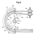
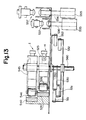
- FIGS 12 and 13 depict a biventricular assist dual pulsatile monoroller pump which comprises lower and upper solenoid type monoroller pulsatile pumps H and I.
- the lower deck pump H is assigned to be used for support of the right heart, and the upper deck pump I for the left heart.
- the lower deck pump H has a smaller diameter raceway 520.
- the tail end of this raceway 520 is modular and has two segments 521 and 522 of the raceway arc that can be sequentially slid out away from the roller pathway.
- Light sensors and light reflecting plates have been attached underneath the top of, and within the pump case.
- the opening sensors or pressurizing angle sensors 531, 551 are independently adjustable between 0° and 90°; the closing sensors 532, 552 are adjustable between 90° and 330°, to be used normally at 180°.
- the sensors 531 and 532 are for the pump H while the sensors 551 and 552 are for the pump I. These sensors should be adjustable from the outside of the pump case and while the pump is in operation.
- These sensors send their respective signals to their respective solenoids 535, 555, the solenoid 535 being for the pump H while the sensor 555 is for the pump I.
- Two identical sets of clamps, 537 for the pump H and 557 for the pump I, are required, each with their independent tube occlusiveness control 538, 558 as well as their respective occluding push rods 536, 556 to transmit the motion of the solenoids.
- the roller bearing rotating arms 525 and 545 have built in their respective roller occlusiveness control mechanisms 527 and 547, so that each roller occlusiveness can be adjusted separately.
- the tail end or exit side of the raceway has been divided in 4 segments 70, 71, 72 and 73, each having basically a rectangular shape. Of these, segments 72 and 73 are stationary. The segment 73 is the main body of the raceway. The segment 72 is actually not a part of the raceway in itself, but is an extra segment that has been added to provide an anchoring point for the sliding components.
- the segments 70 and 71 are the two sliding raceway arc segments, and are held between the stationary segments 72 and 73. In order to provide the ability to slide in and out the roller path, these sliding segments are fastened to each other and to the stationary components with either wedge shape or rectangular shape rail type interlocking fasteners 80 and 81.
- the two fasteners 81 adjacent to the stationary components are attached to their respective stationary segments.
- the fastener 80 is attached to the sliding segment 70.
- the interlocking fasteners 80 and 81 will provide the stability in terms of up and down motion of the sliding segments.
- those sliding segments In order to maintain the uniform occlusiveness of these raceway arc segments when being used as raceways, those sliding segments must be firmly secured against an inner stopper 74 with a convexity that conforms exactly to the concavity of the raceway arc segments.
- the components 75, 76 and 77 constitute the elements that move and fix the sliding segments.
- the component 75 is stationary and holds the mast bolt attached to the sliding segments.
- a double nut system 76, 77 screwed on this mast bolt the sliding segments 70 and 71 can be not only slid in against the stopper 74 or out away from the stopper, but also they can be fixed and locked in the desired position.
- FIGs 16 and 17 depict the biventricular assist dual pulsatile monoroller pump made out of two superimposed cam type monoroller pulsatile pumps J and K.
- the cam type monoroller pulsatile pump is less versatile than the solenoid type to alter the stroke volume without changing pump head tubing or stopping the pump, since the outlet clamp is actuated mechanically. However, by modifying the stationary component of this clamp it can be made to close with variable and controllable delay to induce the transient back flow.
- the two superimposed monoroller pumps J and K share the same rotational axis 660; the lower deck pump J has a smaller raceway 620 than the upper deck pump K.
- the cam 661 is comprised of upper and lower members and common for both outlet clamps 637 and 657 which share the same moving occluding push rod 636.
- the opposing stationary occluders 637a and 657a are separate. This stationary occluder has been modified to make it actually mobile independently from the cam, mediated by a solenoid 635, 655.
- a reflecting plate 630 common for the sensors of both pumps, is attached to the main rotational axis inside the box of the pump, underneath the top table of the pump, and exactly parallel to the rotating arms of the pumps.
- the sensors that send the signals for activation of the solenoids to close or open their respective clamps are separate; the timing for closure of each of the clamps is independently controllable from the outside of the pump box, thus the duration or amount of the transient back flow can be varied from zero to whatever angle has been chosen in order to adjust the net forward flow of each of the pumps.
- the sensors 631 and 651 to activate the opening of the clamps are permanently fixed at any point beyond the ⁇ 1 angle of the rotating arms, but way before the cam starts to close the clamp.
- the sensors 632 and 652 that activate the closure of their respective clamps are normally set and locked at a point slightly before the cam closes the clamps.
- the occluder By adding a mechanical locking mechanism to the solenoid driven portion of the clamp itself, i.e., the occluder can be kept in the closed position, and truly stationary, as it would normally be used, mechanically, without the need of activating the solenoid when the back flow is not desired.
- Each of the pumps (upper deck pump with the larger stroke volume, and the lower deck pump with the smaller stroke volume) will function separately exactly as the desired pulsatile monoroller pump. Since they are superimposed and share the same rotational axis, the flow rate of one pump can not be changed, by adjusting speed of rotation or pulse frequency, without influencing that of the other pump. Since in the great majority of patients needing biventricular support (right and left ventricles or hearts), the right heart requires less assist flow rate to begin with and recovers sooner than the left, the need for different assist flow rates becomes obvious.
- This pump is designed so that the lower deck pump has a smaller stroke volume, and therefore lower flow rate than the upper deck pump.
- the lower deck raceway is modular, so that the effective arc length can be made shorter, decreasing further the stroke volume. If a change of the stroke volume is not desired but the net forward flow needs to be decreased, then a transient period of back-flow can be created by making the outlet tube clamp close after the roller has left the raceway. Adjusting the amount of back-flow by controlling the timing of the outlet clamp closure in relation to the cycle of the pump, will effectively curtail the net forward flow of one pump while keeping the same r.p.m. to maintain the upper deck pump flow rate constant.
- the closure time of the outlet clamp can similarly be moved to allow some back-flow, thus decreasing the net forward minute flow rate.
- Delivering a full stroke volume at a relatively fast frequency or r.p.m. maintains an effective washout phenomenon, an important factor to avoid clotting inside the tubing, which is apt to occur at low r.p.m. or pulse frequency.
- This problem mars even the specially designed cardiac assist valved pumps (pneumatically driven sac types, or electrically driven pusher plate types) when used at low flow rate.
Landscapes
- Health & Medical Sciences (AREA)
- Engineering & Computer Science (AREA)
- Heart & Thoracic Surgery (AREA)
- Cardiology (AREA)
- Life Sciences & Earth Sciences (AREA)
- Public Health (AREA)
- Biomedical Technology (AREA)
- Hematology (AREA)
- Mechanical Engineering (AREA)
- Animal Behavior & Ethology (AREA)
- General Health & Medical Sciences (AREA)
- Anesthesiology (AREA)
- Veterinary Medicine (AREA)
- Pulmonology (AREA)
- Emergency Medicine (AREA)
- Human Computer Interaction (AREA)
- Medical Informatics (AREA)
- External Artificial Organs (AREA)
- Reciprocating Pumps (AREA)
Applications Claiming Priority (4)
| Application Number | Priority Date | Filing Date | Title |
|---|---|---|---|
| JP288363/86 | 1986-12-03 | ||
| JP61288363A JPS63143076A (ja) | 1986-12-03 | 1986-12-03 | 拍動流ポンプ |
| JP794287U JPH0349710Y2 (fr) | 1987-01-22 | 1987-01-22 | |
| JP7942/87 | 1987-01-22 |
Publications (2)
| Publication Number | Publication Date |
|---|---|
| EP0269898A2 true EP0269898A2 (fr) | 1988-06-08 |
| EP0269898A3 EP0269898A3 (fr) | 1989-09-06 |
Family
ID=26342346
Family Applications (1)
| Application Number | Title | Priority Date | Filing Date |
|---|---|---|---|
| EP87116235A Withdrawn EP0269898A3 (fr) | 1986-12-03 | 1987-11-04 | Appareil pour délivrer un courant pulsé |
Country Status (4)
| Country | Link |
|---|---|
| US (1) | US4976593A (fr) |
| EP (1) | EP0269898A3 (fr) |
| KR (1) | KR950002536B1 (fr) |
| CA (1) | CA1296591C (fr) |
Cited By (3)
| Publication number | Priority date | Publication date | Assignee | Title |
|---|---|---|---|---|
| EP0330761A1 (fr) * | 1988-02-27 | 1989-09-06 | Fresenius AG | Procédé de mesure et d'indication dans des systémes à liquide d'appareils médicaux et dispositif pour la mise en oeuvre du procédé |
| WO2011003595A1 (fr) | 2009-07-06 | 2011-01-13 | King Saud University | Dispositif de pompage de sang |
| EP4037722A4 (fr) * | 2019-09-19 | 2024-01-24 | Triphasic Cardiac Pump Pty Ltd | Pompe pour imiter un débit sanguin physiologique chez un patient |
Families Citing this family (32)
| Publication number | Priority date | Publication date | Assignee | Title |
|---|---|---|---|---|
| US5215450A (en) * | 1991-03-14 | 1993-06-01 | Yehuda Tamari | Innovative pumping system for peristaltic pumps |
| US5336051A (en) * | 1989-09-22 | 1994-08-09 | Yehuda Tamari | Inline non-invasive pressure monitoring system for pumps |
| US5342181A (en) * | 1992-06-15 | 1994-08-30 | Datascope Investment Corp. | Single roller blood pump and pump/oxygenator system using same |
| US5711654A (en) * | 1995-06-07 | 1998-01-27 | Baxter International Inc. | Peristaltic pump with rotor position sensing employing a reflective object sensor |
| US5916191A (en) * | 1996-04-30 | 1999-06-29 | Medtronic, Inc. | Pulsatile flow generation in heart-lung machines |
| JPH1018973A (ja) * | 1996-06-28 | 1998-01-20 | Tamagawa Nagao | チューブポンプ |
| JP3587226B2 (ja) | 1996-07-11 | 2004-11-10 | セイコーエプソン株式会社 | インクジェット記録装置およびそれに用いられるポンプ |
| US6099272A (en) * | 1997-09-18 | 2000-08-08 | Fsi International | Peristaltic pump with flow control |
| US6977140B1 (en) | 1998-09-29 | 2005-12-20 | Organ Recovery Systems, Inc. | Method for maintaining and/or restoring viability of organs |
| US6673594B1 (en) * | 1998-09-29 | 2004-01-06 | Organ Recovery Systems | Apparatus and method for maintaining and/or restoring viability of organs |
| EP1141547A1 (fr) * | 1998-12-17 | 2001-10-10 | Claude F. Mondiere | Pompe a sang neonatale |
| US6620121B1 (en) * | 1999-05-27 | 2003-09-16 | East Carolina University | Pulse wave generator for cardiopulmonary bypass and extracorporeal oxygenation apparatus |
| ITCS990022A1 (it) * | 1999-12-16 | 2000-03-16 | Luise Renata De | Circolatore extracorporeo pulsatile secondario da accoppiare ad un cir cuito dotato di circolatore a flusso continuo. |
| US6406267B1 (en) | 2000-06-16 | 2002-06-18 | Claude F. Mondiere | Extracorporeal circulation pump |
| US20110098624A1 (en) * | 2001-02-14 | 2011-04-28 | Mccotter Craig | Method and apparatus for treating renal disease with hemodialysis utilizing pulsatile pump |
| US6722865B2 (en) | 2001-09-07 | 2004-04-20 | Terumorcardiovascular Systems Corporation | Universal tube clamp assembly |
| US7150607B2 (en) * | 2002-11-18 | 2006-12-19 | International Remote Imaging Systems, Inc. | Uniform flow displacement pump |
| US7118203B2 (en) * | 2003-08-25 | 2006-10-10 | Hewlett-Packard Development Company, L.P. | Peristaltic pump |
| US8393879B2 (en) * | 2004-04-27 | 2013-03-12 | Hewlett-Packard Development Company, L.P. | Peristaltic pump |
| US7591639B2 (en) * | 2004-04-27 | 2009-09-22 | Hewlett-Packard Development Company, L.P. | Peristaltic pump |
| US7878773B2 (en) * | 2004-10-12 | 2011-02-01 | Maztech, Inc. | Dynamically tensioned peristaltic tubing pump |
| US8317499B2 (en) * | 2005-11-18 | 2012-11-27 | Araz Ibragimov | Pulsatile peristaltic pump for use in a cardiopulmonary bypass |
| US8079836B2 (en) * | 2006-03-01 | 2011-12-20 | Novartis Ag | Method of operating a peristaltic pump |
| US20080249456A1 (en) * | 2007-03-27 | 2008-10-09 | Syuuji Inamori | Pulsation-type auxiliary circulation system, pulsatile flow generation control device, and pulsatile flow generation control method |
| US8074809B2 (en) * | 2009-07-17 | 2011-12-13 | Gordon H. King | Apparatus and method for the treatment of liquid/solid mixtures |
| US8870025B2 (en) * | 2009-10-23 | 2014-10-28 | Nestec S.A. | Method and device for aseptically dispensing multiple portions of a fluid |
| JP5962894B2 (ja) * | 2012-03-09 | 2016-08-03 | 国立大学法人広島大学 | 送血流量制御装置および体外循環装置 |
| US20140154640A1 (en) * | 2012-11-30 | 2014-06-05 | Techtronic Floor Care Technology Limited | Dental hygiene device |
| AU2019207523B2 (en) * | 2018-01-11 | 2023-11-02 | Triphasic Cardiac Pump Pty Ltd | "Cardiac pump" |
| JP7300453B2 (ja) * | 2018-08-27 | 2023-06-29 | 日機装株式会社 | 血液浄化装置 |
| US20240082475A1 (en) * | 2020-11-25 | 2024-03-14 | Cytostorm, Inc. | Extracorporeal plasma separation, adsorption, and delivery systems and methods |
| CN113713209B (zh) * | 2021-08-27 | 2022-06-07 | 四川大学华西医院 | 一种高精度镇痛泵及控制方法 |
Family Cites Families (21)
| Publication number | Priority date | Publication date | Assignee | Title |
|---|---|---|---|---|
| GB190206361A (en) * | 1902-03-15 | 1903-01-29 | Alexander Munro | Improvements in Reservoir Pens and the like. |
| DE1653397A1 (de) * | 1966-01-10 | 1971-07-08 | Ceskoslovenska Akademie Ved | Verfahren und Einrichtung zum Foerdern von Fluessigkeiten in duennen Schlaeuchen |
| US3431864A (en) * | 1966-12-22 | 1969-03-11 | Charles B Jones Jr | Peristaltic pump |
| FR1527784A (fr) * | 1967-01-10 | 1968-06-07 | Ceskoslovenska Akademie Ved | Procédé et dispositif pour la circulation des liquides dans des flexibles minces |
| GB1330833A (en) * | 1969-10-07 | 1973-09-19 | Marsson Ind Ltd | Peristaltic pump |
| US3620650A (en) * | 1969-12-05 | 1971-11-16 | Robert F Shaw | Gas-disabled liquid-pumping apparatus |
| US3679331A (en) * | 1970-04-24 | 1972-07-25 | Delta Scient Corp | Metering pump and valve |
| DE2148468A1 (de) * | 1970-10-08 | 1972-04-13 | Snam Progetti | Peristaltische Pumpe mit mehreren kontinuierlich einstellbaren Kanaelen |
| US3726613A (en) * | 1970-10-12 | 1973-04-10 | Casimir W Von | Pulsefree peristaltic pump |
| US3811800A (en) * | 1972-07-12 | 1974-05-21 | K Shill | Blood pump |
| US3935885A (en) * | 1974-02-01 | 1976-02-03 | Alter Richard R | Capsule-filling machines |
| IL44372A (en) * | 1974-03-08 | 1976-10-31 | Drori Mordeki | Fluid-driven feeding device for liquid materials |
| US4165954A (en) * | 1975-08-11 | 1979-08-28 | Corning Glass Works | Linear peristaltic pump having pivotal pump arm |
| US4080958A (en) * | 1976-02-27 | 1978-03-28 | Datascope Corporation | Apparatus for aiding and improving the blood flow in patients |
| US4273121A (en) * | 1978-02-17 | 1981-06-16 | Andros Incorporated | Medical infusion system |
| DE2849048A1 (de) * | 1978-11-11 | 1980-05-14 | Gutehoffnungshuette Sterkrade | Zwangssteuerungssystem fuer kolbenverdichter-ventile |
| DE3131075C2 (de) * | 1981-08-05 | 1984-01-19 | Dr. Eduard Fresenius, Chemisch-pharmazeutische Industrie KG, 6380 Bad Homburg | Vorrichtung zum Reinigen von Blut |
| JPS58190447A (ja) * | 1982-04-30 | 1983-11-07 | 株式会社クラレ | 脈動発生装置 |
| US4568255A (en) * | 1984-11-16 | 1986-02-04 | Armour Pharmaceutical | Peristaltic roller pump |
| US4651490A (en) * | 1986-03-07 | 1987-03-24 | Syenergy Methods, Inc. | Fastening assembly for mechanically attaching a flexible membrane to a roof construction |
| US4767289A (en) * | 1986-12-31 | 1988-08-30 | Minnesota Mining And Manufacturing Company | Peristaltic pump header |
-
1987
- 1987-10-30 CA CA000550738A patent/CA1296591C/fr not_active Expired - Fee Related
- 1987-11-04 EP EP87116235A patent/EP0269898A3/fr not_active Withdrawn
- 1987-12-03 KR KR1019870013772A patent/KR950002536B1/ko not_active Expired - Lifetime
-
1989
- 1989-04-07 US US07/334,577 patent/US4976593A/en not_active Expired - Fee Related
Cited By (4)
| Publication number | Priority date | Publication date | Assignee | Title |
|---|---|---|---|---|
| EP0330761A1 (fr) * | 1988-02-27 | 1989-09-06 | Fresenius AG | Procédé de mesure et d'indication dans des systémes à liquide d'appareils médicaux et dispositif pour la mise en oeuvre du procédé |
| WO2011003595A1 (fr) | 2009-07-06 | 2011-01-13 | King Saud University | Dispositif de pompage de sang |
| US8840382B2 (en) | 2009-07-06 | 2014-09-23 | King Saud University | Blood-pumping device |
| EP4037722A4 (fr) * | 2019-09-19 | 2024-01-24 | Triphasic Cardiac Pump Pty Ltd | Pompe pour imiter un débit sanguin physiologique chez un patient |
Also Published As
| Publication number | Publication date |
|---|---|
| CA1296591C (fr) | 1992-03-03 |
| KR880007094A (ko) | 1988-08-26 |
| EP0269898A3 (fr) | 1989-09-06 |
| KR950002536B1 (ko) | 1995-03-21 |
| US4976593A (en) | 1990-12-11 |
Similar Documents
| Publication | Publication Date | Title |
|---|---|---|
| CA1296591C (fr) | Generateur d'ecoulement pulsatoire | |
| EP0902689B1 (fr) | Generation de pression pulsatoire dans un coeur-poumon artificiel | |
| US7811221B2 (en) | Extracardiac blood flow amplification device | |
| US4360324A (en) | Pulsatile blood pump | |
| US7850593B2 (en) | Fluid pump | |
| US12005247B2 (en) | Pump for artificial circulatory assistance and a pumping system | |
| US4902272A (en) | Intra-arterial cardiac support system | |
| US5222980A (en) | Implantable heart-assist device | |
| CN101856520B (zh) | 全人工心脏装置 | |
| US5743845A (en) | Biventricular pulsatile cardiac support system having a mechanically balanced stroke volume | |
| WO2003068292A1 (fr) | Dispositif et procede d'assistance cardiaque physiologiquement compatible | |
| CA2121809A1 (fr) | Appareil de massage cardiaque | |
| US5314469A (en) | Artificial heart | |
| HU191321B (en) | Blood pump | |
| JPH01136664A (ja) | 拍動ポンプ装置 | |
| US4969864A (en) | Venticular assist device | |
| JPS61244370A (ja) | 血液潅流に用いられるポンプ装置および血液潅流カテ−テルの作動方法 | |
| WO2025072858A1 (fr) | Dispositifs, systèmes et procédés d'assistance cardiaque | |
| WO2001043797A2 (fr) | Pompe ou modulateur pulsatoire extracorporel a ajouter a un systeme de perfusion a ecoulement extracorporel continu | |
| Edelman et al. | TIMING DURING CONCOMITANT ABDOMINAL LEFT VENTRICULAR ASSIST DEVICE (ALVAD) AND INTRA–AORTIC BALLOON PUMPING (IABP) IN MAN | |
| JP2025059330A (ja) | 体外循環血液システム、および体外循環血液システムの使用方法 | |
| Sasaki et al. | A small pulsatile pump for extracorporeal circulation | |
| Zwarts et al. | A computer controlled pulsatile pump: preliminary study | |
| Chesnut et al. | Assisted circulation controlled by electronic computation | |
| JP2023501051A (ja) | 患者における生理的血流を模倣するためのポンプ |
Legal Events
| Date | Code | Title | Description |
|---|---|---|---|
| PUAI | Public reference made under article 153(3) epc to a published international application that has entered the european phase |
Free format text: ORIGINAL CODE: 0009012 |
|
| AK | Designated contracting states |
Kind code of ref document: A2 Designated state(s): DE FR GB IT SE |
|
| PUAL | Search report despatched |
Free format text: ORIGINAL CODE: 0009013 |
|
| AK | Designated contracting states |
Kind code of ref document: A3 Designated state(s): DE FR GB IT SE |
|
| 17P | Request for examination filed |
Effective date: 19900118 |
|
| 17Q | First examination report despatched |
Effective date: 19910328 |
|
| STAA | Information on the status of an ep patent application or granted ep patent |
Free format text: STATUS: THE APPLICATION IS DEEMED TO BE WITHDRAWN |
|
| 18D | Application deemed to be withdrawn |
Effective date: 19911008 |
|
| RIN1 | Information on inventor provided before grant (corrected) |
Inventor name: MIYAMOTO, ALFONSO TADAOMI |