EP0269969A2 - Elément superposé pour ouvertures de toit dans des constructions - Google Patents
Elément superposé pour ouvertures de toit dans des constructions Download PDFInfo
- Publication number
- EP0269969A2 EP0269969A2 EP87117202A EP87117202A EP0269969A2 EP 0269969 A2 EP0269969 A2 EP 0269969A2 EP 87117202 A EP87117202 A EP 87117202A EP 87117202 A EP87117202 A EP 87117202A EP 0269969 A2 EP0269969 A2 EP 0269969A2
- Authority
- EP
- European Patent Office
- Prior art keywords
- upper portion
- lower portion
- superimposed
- roof
- arm
- Prior art date
- Legal status (The legal status is an assumption and is not a legal conclusion. Google has not performed a legal analysis and makes no representation as to the accuracy of the status listed.)
- Granted
Links
- 238000007789 sealing Methods 0.000 claims abstract description 16
- 239000011324 bead Substances 0.000 claims description 3
- 239000004033 plastic Substances 0.000 claims description 3
- 229920003023 plastic Polymers 0.000 claims description 3
- 239000003000 extruded plastic Substances 0.000 claims description 2
- 239000000853 adhesive Substances 0.000 claims 1
- 230000001070 adhesive effect Effects 0.000 claims 1
- 239000000463 material Substances 0.000 abstract description 3
- 230000007704 transition Effects 0.000 abstract 1
- 239000012528 membrane Substances 0.000 description 4
- 238000010276 construction Methods 0.000 description 3
- 230000006835 compression Effects 0.000 description 2
- 238000007906 compression Methods 0.000 description 2
- 230000035515 penetration Effects 0.000 description 2
- 238000007788 roughening Methods 0.000 description 2
- 239000004411 aluminium Substances 0.000 description 1
- 229910052782 aluminium Inorganic materials 0.000 description 1
- XAGFODPZIPBFFR-UHFFFAOYSA-N aluminium Chemical compound [Al] XAGFODPZIPBFFR-UHFFFAOYSA-N 0.000 description 1
- 230000006378 damage Effects 0.000 description 1
- 238000005553 drilling Methods 0.000 description 1
- 238000001125 extrusion Methods 0.000 description 1
- 239000011810 insulating material Substances 0.000 description 1
- 238000004519 manufacturing process Methods 0.000 description 1
- 229910052751 metal Inorganic materials 0.000 description 1
- 239000002184 metal Substances 0.000 description 1
- 229920000642 polymer Polymers 0.000 description 1
- 230000001681 protective effect Effects 0.000 description 1
- 239000003566 sealing material Substances 0.000 description 1
- 238000007493 shaping process Methods 0.000 description 1
- XLYOFNOQVPJJNP-UHFFFAOYSA-N water Substances O XLYOFNOQVPJJNP-UHFFFAOYSA-N 0.000 description 1
Images

Classifications
-
- E—FIXED CONSTRUCTIONS
- E04—BUILDING
- E04D—ROOF COVERINGS; SKY-LIGHTS; GUTTERS; ROOF-WORKING TOOLS
- E04D13/00—Special arrangements or devices in connection with roof coverings; Protection against birds; Roof drainage ; Sky-lights
- E04D13/14—Junctions of roof sheathings to chimneys or other parts extending above the roof
- E04D13/1407—Junctions of roof sheathings to chimneys or other parts extending above the roof for flat roofs
- E04D13/1415—Junctions to walls extending above the perimeter of the roof
-
- E—FIXED CONSTRUCTIONS
- E04—BUILDING
- E04D—ROOF COVERINGS; SKY-LIGHTS; GUTTERS; ROOF-WORKING TOOLS
- E04D13/00—Special arrangements or devices in connection with roof coverings; Protection against birds; Roof drainage ; Sky-lights
- E04D13/03—Sky-lights; Domes; Ventilating sky-lights
- E04D13/0305—Supports or connecting means for sky-lights of flat or domed shape
- E04D13/0315—Supports or connecting means for sky-lights of flat or domed shape characterised by a curb frame
Definitions
- the invention relates to a superimposed member for roof openings of buildings.
- an upper portion which is formed by a domelight, is connected to a lower portion of the superimposed member by means of a mounting device.
- the upper portion of the superimposed member is located on the lower portion of the superimposed member by toggle bolts or the like disposed at the inside of the upper portion of the superimposed member.
- toggle bolts such as so-called quick-acting tensioners or eccentric snap closures, including those of ordinary commercial construction, may be used in connection with the location of the upper portion of the superimposed member on the lower portion according to the invention.
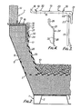
- a rectangular roof opening 4 is formed in a horizontal or slightly inclined roof 1, which is represented by an upper layer of trapezoidal plates 2 and an insulating layer 3.
- a roof membrane 5 in the form of a plastics sheet, such as a high-polymer or PVC sheet, and placed on this is a lower portion 6 of a superimposed member which is designated as a whole by 7.
- the lower portion 6 has the form of a base which surrounds the roof opening 4 on all sides and bounds this by its inside 8 and extends it upwards according to its height.
- the lower portion 6 consists essentially of heat-insulating material in which a bent-up end piece of the roof membrane 5 is included.
- a flashing 9 which is formed from a plastics sheet corresponding to the roof membrane 5 and on which there is also gravel ballasting 10. The flashing 9 is pulled up, by its end region, at the outside 11 of the lower portion 6.
- the superimposed member 7 further comprises an upper portion 12 in the form of a housing which is placed over an angle-section bar member, designated as a whole by 13, with its under side on the upper side of the lower portion 6, adjacent to its inside 8, and engages with an outer arm 14 with a marginal flange 15 bent down at an angle, in a protective manner over the upper outer marginal region of the angle-section bar member 13.
- the sectional shape of the angle-section bar member 13 can be seen, in particular, from Figure 3.
- the angle-section bar member 13 has two section arms 16 and 17 which are disposed at right angles to one another and of which the sectional arm 16 forms a horizontal arm and the sectional arm 17 a vertical or downwardly extending arm in the installed state of the member 13.
- the horizontal arm 16 is provided with an upright marginal strip 18 at its inner longitudinal edge adjacent to the roof opening 4 and otherwise comprises sealing lips 19 extending along its two longitudinal edges.
- Distance beads 20 are disposed along the sealing lips 19, towards the middle of the sectional arm 16.
- the sealing lips 19 consist of a softer material than the other material of the angle-section bar member 13 and can be formed on the sectional arm by co-extrusion during the production of the one-piece extruded plastics sectional member forming the member 13.
- the angle-section bar member 13 consists of hard PVC while the sealing lips 19 consist of soft PVC.
- the sealing lips 19 have the oblique alignment outwards towards the particular adjacent longitudinal edge of the sectional arm 16, which can be seen in particular from Figure 3, while the height of the distance bead adjacent to the sealing lips 19 at the inside causes a defined extent of the compression of the sealing lips 19 by the superimposed upper portion 12 and at the same time prevents a complete compression of the sealing lips 19 which could otherwise lead to a destruction of the sealing material.
- the vertical arm 17 of the angle-section bar membr 13 is engaged over, in its upper end region, by an outer marginal flange 21 which is disposed with spacing from the outside of the vertical arm 17 in such a manner that a cavity 22 is formed which is open at the bottom.
- the cavity 22 is constructed, in its region adjacent to its lower opening, in the form of a detent groove 23 in which a cover strip 24, which can be seen from Figure 4, can be inserted with a gripping action by a head end 25 shaped according to the section of the detent groove 23.
- the cover strip 24 consists of metal and is formed from an aluminium sectional member in the example illustrated. It comprises an attachment portion 26 which is offset outwards by a bend 27 following on the head end.
- the attachment portion 26 serves to receive mechanical attachment elements, particularly screws, for a clamping connection of a pent course to the vertical arm 17 of the angle-section bar member 13.
- Figure 1 shows a connection of the flashing 9 to the vertical arm 17 of the angle-section bar member 13 by a direct adhesion of the flashing 9 to an adhesion surface offered by the outside of the sectional arm 17.
- the sectional arm 17 bears with its inside against the lower portion 6 and has a course facing downwards in accordance with its outside.
- Figure 2 illustrates an embodiment wherein the insulating layer 3 extends obliquely upwards at the inside.
- the lower portion 6 of the superimposed member 7 extends correspondingly obliquely upwards in its region adjacent to the insulating layer 3 and ends in a vertical head portion.
- the construction is the same as in Figure 1 except that instead of a single flashing 9, two flashings 28 and 29 are provided.
- the flashings 28 and 29 consist of pieces of bituminous sheet corresponding to the upper skin of the roof 1, which are clamped to the outside of the vertical arm 17 of the angle-section bar 13 by means of the cover strip 24.
- the cover strip 24 is inserted by its head end 25 in the detent groove 23 with a gripping action, as can be seen from figure 2. Then the correspondingly raised ends of the flashings 28 and 29 are clamped on, in their end region engaged over by the cover strip 24, by means of screws which, as indicated at 30, are screwed through the cover strip 24, the two flashings 28 and 29 and through the vertical arm 24.
- the bend 27 forms a secure covering of the upper edges of the flashings 28 and 29 so that the penetration of water through rainfall is reliably prevented.
- the latter can be provided with a roughening 31 (Figure 3) at its outside, while the cover strip 24 has corresponding roughening 32 ( Figure 4) at its inside.
- quick-acting toggle bolts 115 are provided which are secured, for example screwed, to the inside 8 of the lower portion 6 in a number and distribution corresponding to the size of the roof opening 4 or of the superimposed member 11.
- Each quick-acting toggle bolt 115 comprises a bearing member 116 which is secured to the inside 8 of the lower portion 6, and has a base plate 117 directed downwards towards the roof opening 4, as well as a locking hook 119 which can be actuated by means of a tensioning lever 118 and which can be brought into locking engagement with a receiving member 121 provided on the inside 120 of the upper portion 12 in order to locate the latter.
- the tensioning lever 118 is pivotally mounted, by means of a pivot pin 122, in the bearing member 116 and is constructed in a manner known per se in the form of an eccentric lever in that a shank 124 is pivotally and eccentrically connected to the tensioning lever 118 by means of a swivel axis 123 and receives, at one end, a rod 125 comprising the hook 119 at the end.
- the rod 125 is adjustable in height in the shank 124, in that it can, for example, be screwed more or less deep into the shank 124 by means of a threaded connection. In this manner, the correct amount of spacing of the locking hook 119 can be produced for its co-operation with the receiving member 121 of the upper portion 12.
- the receiving member 121 of the upper portion 12 consists of a sectional member which offers a channel-shaped receiving cross-section for the locking hook 119 and which can be formed from a corresponding integral sectional shaping of the inner wall of the upper portion 12.
- this sectional member may be formed from a separate added piece which is screwed or riveted onto the inside 120 of the upper portion 12 as indicated at 126.
- the quick-acting toggle bolt 115 illustrated is shown in chain lines in its position out of engagement and in full lines in its locking position in which the tensioning lever 118 is beyond the dead centre position.
- the tensioning lever 118 is pivoted about its pivot axis 122 in counter-clockwise direction, the entrainment of the locking hook 119 guided in the receiving member 121 and connected eccentrically to the tensioning lever 118 at 123 is effected as is its clamping on the receiving member 121 with the tensioning lever 118 pivoted by the pivot axis 123 via the pivot axis 122 inwards towards the inside 8 of the lower portion 6, to beyond the dead centre position.
- the tensioning lever 118 can be locked in this tensioning position by means of an interlocking mechanism 127 as a safety device against unauthorized opening of the quick-acting toggle bolt 115.
- the interlocking mechanism 127 is secured to the base plate 117 and comprises a receiving member for the tensioning lever 118 and a cover portion which can be locked by means of a lock.
Landscapes
- Engineering & Computer Science (AREA)
- Architecture (AREA)
- Civil Engineering (AREA)
- Structural Engineering (AREA)
- Roof Covering Using Slabs Or Stiff Sheets (AREA)
- Building Environments (AREA)
Priority Applications (1)
| Application Number | Priority Date | Filing Date | Title |
|---|---|---|---|
| AT87117202T ATE64642T1 (de) | 1983-11-11 | 1984-11-09 | Ueber dachoeffnungen von bauten liegender koerper. |
Applications Claiming Priority (4)
| Application Number | Priority Date | Filing Date | Title |
|---|---|---|---|
| DE19838332453U DE8332453U1 (de) | 1983-11-11 | 1983-11-11 | Aufsatzkoerper fuer dachoeffnungen von gebaeuden |
| DE8332453U | 1983-11-11 | ||
| DE19833340860 DE3340860A1 (de) | 1983-11-11 | 1983-11-11 | Aufsatzkoerper fuer dachoeffnungen von gebaeuden |
| DE3340860 | 1983-11-11 |
Related Parent Applications (1)
| Application Number | Title | Priority Date | Filing Date |
|---|---|---|---|
| EP84307751.2 Division | 1984-11-09 |
Publications (3)
| Publication Number | Publication Date |
|---|---|
| EP0269969A2 true EP0269969A2 (fr) | 1988-06-08 |
| EP0269969A3 EP0269969A3 (en) | 1989-03-08 |
| EP0269969B1 EP0269969B1 (fr) | 1991-06-19 |
Family
ID=25815566
Family Applications (2)
| Application Number | Title | Priority Date | Filing Date |
|---|---|---|---|
| EP87117202A Expired - Lifetime EP0269969B1 (fr) | 1983-11-11 | 1984-11-09 | Elément superposé pour ouvertures de toit dans des constructions |
| EP84307751A Expired EP0142965B1 (fr) | 1983-11-11 | 1984-11-09 | Elément superposé pour ouvertures de toit dans des constructions |
Family Applications After (1)
| Application Number | Title | Priority Date | Filing Date |
|---|---|---|---|
| EP84307751A Expired EP0142965B1 (fr) | 1983-11-11 | 1984-11-09 | Elément superposé pour ouvertures de toit dans des constructions |
Country Status (4)
| Country | Link |
|---|---|
| EP (2) | EP0269969B1 (fr) |
| AU (2) | AU569126B2 (fr) |
| DE (2) | DE3476234D1 (fr) |
| NZ (1) | NZ210184A (fr) |
Cited By (4)
| Publication number | Priority date | Publication date | Assignee | Title |
|---|---|---|---|---|
| FR2641300A1 (fr) * | 1989-01-03 | 1990-07-06 | Couvraneuf | Solin pour releve d'etancheite d'un ouvrage |
| EP0377366A1 (fr) * | 1989-01-03 | 1990-07-11 | Couvraneuf Societe Anonyme Dite : | Solin pour relevé d'étanchéité |
| EP1061199A1 (fr) * | 1999-06-18 | 2000-12-20 | VELUX Industri A/S | Chassis isolant pour tabatière |
| EP2568094B2 (fr) † | 2011-09-12 | 2021-03-17 | FAKRO PP Spolka z ograniczona odpowiedzialnoscia | Lucarne, en particulier d'une fenêtre de toit apte à être montée à l'intérieur d'un ensemble de panneaux solaires |
Families Citing this family (2)
| Publication number | Priority date | Publication date | Assignee | Title |
|---|---|---|---|---|
| DE3719257A1 (de) * | 1987-06-10 | 1988-12-22 | Eberspaecher J | Zarge |
| DE9400144U1 (de) * | 1994-01-07 | 1994-02-24 | E.M.B. Metallbau und Brandschutztechnik GmbH, 46446 Emmerich | Aufsatzkörper für Dachöffnungen |
Family Cites Families (7)
| Publication number | Priority date | Publication date | Assignee | Title |
|---|---|---|---|---|
| US2842073A (en) * | 1954-09-29 | 1958-07-08 | Sanford K Huston | Skylight |
| US3417527A (en) * | 1967-01-12 | 1968-12-24 | Brunswick Corp | Skylight dome |
| DE2752414C2 (de) * | 1977-11-24 | 1980-01-24 | Blefa Ag, 5910 Kreuztal | Dachfenster |
| US4193237A (en) * | 1978-06-07 | 1980-03-18 | Imperial Glass Structure | Skylight structure |
| US4409767A (en) * | 1978-07-10 | 1983-10-18 | Wasco Products, Inc. | Skylight construction |
| US4243255A (en) * | 1979-04-06 | 1981-01-06 | Rexnord Inc. | Low silhouette adjustable latch with secondary lock |
| DE3216774A1 (de) * | 1982-05-05 | 1983-11-10 | E.L. Hirz GmbH & Co KG, 4130 Moers | Dachfenster |
-
1984
- 1984-11-09 DE DE8484307751T patent/DE3476234D1/de not_active Expired
- 1984-11-09 EP EP87117202A patent/EP0269969B1/fr not_active Expired - Lifetime
- 1984-11-09 DE DE8787117202T patent/DE3484740D1/de not_active Expired - Lifetime
- 1984-11-09 EP EP84307751A patent/EP0142965B1/fr not_active Expired
- 1984-11-12 NZ NZ210184A patent/NZ210184A/en unknown
- 1984-11-12 AU AU35319/84A patent/AU569126B2/en not_active Ceased
-
1988
- 1988-01-22 AU AU10753/88A patent/AU590143B2/en not_active Ceased
Cited By (7)
| Publication number | Priority date | Publication date | Assignee | Title |
|---|---|---|---|---|
| FR2641300A1 (fr) * | 1989-01-03 | 1990-07-06 | Couvraneuf | Solin pour releve d'etancheite d'un ouvrage |
| EP0377366A1 (fr) * | 1989-01-03 | 1990-07-11 | Couvraneuf Societe Anonyme Dite : | Solin pour relevé d'étanchéité |
| FR2653799A2 (fr) * | 1989-01-03 | 1991-05-03 | Couvraneuf | Solin pour releve d'etancheite d'un ouvrage. |
| EP1061199A1 (fr) * | 1999-06-18 | 2000-12-20 | VELUX Industri A/S | Chassis isolant pour tabatière |
| DK199900873A (da) * | 1999-06-18 | 2001-04-02 | Vkr Holding As | Isoleringsramme for et ovenlysvindue |
| CZ298598B6 (cs) * | 1999-06-18 | 2007-11-21 | Vkr Holding A/S | Izolacní rám |
| EP2568094B2 (fr) † | 2011-09-12 | 2021-03-17 | FAKRO PP Spolka z ograniczona odpowiedzialnoscia | Lucarne, en particulier d'une fenêtre de toit apte à être montée à l'intérieur d'un ensemble de panneaux solaires |
Also Published As
| Publication number | Publication date |
|---|---|
| AU3531984A (en) | 1985-05-16 |
| EP0269969B1 (fr) | 1991-06-19 |
| NZ210184A (en) | 1987-06-30 |
| AU1075388A (en) | 1988-04-28 |
| AU569126B2 (en) | 1988-01-21 |
| DE3476234D1 (en) | 1989-02-23 |
| EP0142965A3 (en) | 1985-12-27 |
| EP0142965A2 (fr) | 1985-05-29 |
| EP0142965B1 (fr) | 1989-01-18 |
| DE3484740D1 (de) | 1991-07-25 |
| AU590143B2 (en) | 1989-10-26 |
| EP0269969A3 (en) | 1989-03-08 |
Similar Documents
| Publication | Publication Date | Title |
|---|---|---|
| US4483112A (en) | Roof edge system | |
| US4419850A (en) | Gravel curb | |
| US5349801A (en) | Sheet metal shingle | |
| CA2149507C (fr) | Bande de fixation pour couvertures en feuilles | |
| US5737892A (en) | Channel-mounted interlocking panel roofing structure | |
| US4930275A (en) | Skylight assembly | |
| EP0306880B1 (fr) | Panneau de toiture modulaire | |
| US2610593A (en) | Skylight construction | |
| US3461625A (en) | Self-flashing skylight curb construction | |
| CA1070471A (fr) | Barriere isolante pour lanternaux, etc. | |
| CA2073214C (fr) | Solin pour membrane d'etancheite pour toitures | |
| US4928445A (en) | Skylight construction | |
| US4067152A (en) | Fascia compression clip | |
| US4335546A (en) | Extruded aluminum termination bar | |
| US3503162A (en) | Combination water cant,sealer strip and fascia | |
| EP0269969B1 (fr) | Elément superposé pour ouvertures de toit dans des constructions | |
| US4995208A (en) | Skylight construction | |
| US5619827A (en) | Roof edge flashing and anchoring system | |
| CA2849364C (fr) | Fenetre de toit munie d'un moyen de recouvrement pour cadre | |
| EP2990563A1 (fr) | Élément de fixation et écran de protection contre les intempéries | |
| EP1567732B1 (fr) | Solin et procede d'installation d'une structure penetrant dans un toit au moyen dudit solin | |
| JPS5814746Y2 (ja) | パラペツト笠木の固定装置 | |
| EP1203129B1 (fr) | Utilisation d'un dispositif d'attache destine a un chaperon de toiture | |
| US5737891A (en) | Channel-mounted interlocking panel roofing structure | |
| US20060048461A1 (en) | Connectors for roofs |
Legal Events
| Date | Code | Title | Description |
|---|---|---|---|
| PUAI | Public reference made under article 153(3) epc to a published international application that has entered the european phase |
Free format text: ORIGINAL CODE: 0009012 |
|
| AC | Divisional application: reference to earlier application |
Ref document number: 142965 Country of ref document: EP |
|
| AK | Designated contracting states |
Kind code of ref document: A2 Designated state(s): AT BE CH DE FR GB LI NL |
|
| PUAL | Search report despatched |
Free format text: ORIGINAL CODE: 0009013 |
|
| AK | Designated contracting states |
Kind code of ref document: A3 Designated state(s): AT BE CH DE FR GB LI NL |
|
| 17P | Request for examination filed |
Effective date: 19890227 |
|
| 17Q | First examination report despatched |
Effective date: 19900425 |
|
| GRAA | (expected) grant |
Free format text: ORIGINAL CODE: 0009210 |
|
| AC | Divisional application: reference to earlier application |
Ref document number: 142965 Country of ref document: EP |
|
| AK | Designated contracting states |
Kind code of ref document: B1 Designated state(s): AT BE CH DE FR GB LI NL |
|
| REF | Corresponds to: |
Ref document number: 64642 Country of ref document: AT Date of ref document: 19910715 Kind code of ref document: T |
|
| ET | Fr: translation filed | ||
| REF | Corresponds to: |
Ref document number: 3484740 Country of ref document: DE Date of ref document: 19910725 |
|
| PLBE | No opposition filed within time limit |
Free format text: ORIGINAL CODE: 0009261 |
|
| STAA | Information on the status of an ep patent application or granted ep patent |
Free format text: STATUS: NO OPPOSITION FILED WITHIN TIME LIMIT |
|
| 26N | No opposition filed | ||
| PGFP | Annual fee paid to national office [announced via postgrant information from national office to epo] |
Ref country code: GB Payment date: 19921030 Year of fee payment: 9 |
|
| PG25 | Lapsed in a contracting state [announced via postgrant information from national office to epo] |
Ref country code: GB Effective date: 19931109 |
|
| GBPC | Gb: european patent ceased through non-payment of renewal fee |
Effective date: 19931109 |
|
| PGFP | Annual fee paid to national office [announced via postgrant information from national office to epo] |
Ref country code: FR Payment date: 19961024 Year of fee payment: 13 |
|
| PGFP | Annual fee paid to national office [announced via postgrant information from national office to epo] |
Ref country code: BE Payment date: 19961029 Year of fee payment: 13 |
|
| PGFP | Annual fee paid to national office [announced via postgrant information from national office to epo] |
Ref country code: CH Payment date: 19961126 Year of fee payment: 13 |
|
| PGFP | Annual fee paid to national office [announced via postgrant information from national office to epo] |
Ref country code: NL Payment date: 19961129 Year of fee payment: 13 |
|
| PG25 | Lapsed in a contracting state [announced via postgrant information from national office to epo] |
Ref country code: LI Free format text: LAPSE BECAUSE OF NON-PAYMENT OF DUE FEES Effective date: 19971130 Ref country code: FR Free format text: THE PATENT HAS BEEN ANNULLED BY A DECISION OF A NATIONAL AUTHORITY Effective date: 19971130 Ref country code: CH Free format text: LAPSE BECAUSE OF NON-PAYMENT OF DUE FEES Effective date: 19971130 Ref country code: BE Free format text: LAPSE BECAUSE OF NON-PAYMENT OF DUE FEES Effective date: 19971130 |
|
| BERE | Be: lapsed |
Owner name: COLT INTERNATIONAL HOLDINGS A.G. Effective date: 19971130 |
|
| PG25 | Lapsed in a contracting state [announced via postgrant information from national office to epo] |
Ref country code: NL Free format text: LAPSE BECAUSE OF NON-PAYMENT OF DUE FEES Effective date: 19980601 |
|
| REG | Reference to a national code |
Ref country code: CH Ref legal event code: PL |
|
| NLV4 | Nl: lapsed or anulled due to non-payment of the annual fee |
Effective date: 19980601 |
|
| REG | Reference to a national code |
Ref country code: FR Ref legal event code: ST |
|
| PGFP | Annual fee paid to national office [announced via postgrant information from national office to epo] |
Ref country code: DE Payment date: 20031209 Year of fee payment: 20 |
|
| PGFP | Annual fee paid to national office [announced via postgrant information from national office to epo] |
Ref country code: AT Payment date: 20031216 Year of fee payment: 20 |
|
| PG25 | Lapsed in a contracting state [announced via postgrant information from national office to epo] |
Ref country code: AT Free format text: LAPSE BECAUSE OF EXPIRATION OF PROTECTION Effective date: 20041109 |