EP0270209A2 - Zirkular polarisierte Antenne für zwei Frequenzbänder mit halbkugelförmiger Richtcharakteristik - Google Patents
Zirkular polarisierte Antenne für zwei Frequenzbänder mit halbkugelförmiger Richtcharakteristik Download PDFInfo
- Publication number
- EP0270209A2 EP0270209A2 EP87307944A EP87307944A EP0270209A2 EP 0270209 A2 EP0270209 A2 EP 0270209A2 EP 87307944 A EP87307944 A EP 87307944A EP 87307944 A EP87307944 A EP 87307944A EP 0270209 A2 EP0270209 A2 EP 0270209A2
- Authority
- EP
- European Patent Office
- Prior art keywords
- patches
- antenna
- structures
- patch
- shorted
- Prior art date
- Legal status (The legal status is an assumption and is not a legal conclusion. Google has not performed a legal analysis and makes no representation as to the accuracy of the status listed.)
- Ceased
Links
Images
Classifications
-
- H—ELECTRICITY
- H01—ELECTRIC ELEMENTS
- H01Q—ANTENNAS, i.e. RADIO AERIALS
- H01Q21/00—Antenna arrays or systems
- H01Q21/24—Combinations of antenna units polarised in different directions for transmitting or receiving circularly and elliptically polarised waves or waves linearly polarised in any direction
-
- H—ELECTRICITY
- H01—ELECTRIC ELEMENTS
- H01Q—ANTENNAS, i.e. RADIO AERIALS
- H01Q5/00—Arrangements for simultaneous operation of antennas on two or more different wavebands, e.g. dual-band or multi-band arrangements
- H01Q5/40—Imbricated or interleaved structures; Combined or electromagnetically coupled arrangements, e.g. comprising two or more non-connected fed radiating elements
- H01Q5/42—Imbricated or interleaved structures; Combined or electromagnetically coupled arrangements, e.g. comprising two or more non-connected fed radiating elements using two or more imbricated arrays
-
- H—ELECTRICITY
- H01—ELECTRIC ELEMENTS
- H01Q—ANTENNAS, i.e. RADIO AERIALS
- H01Q9/00—Electrically-short antennas having dimensions not more than twice the operating wavelength and consisting of conductive active radiating elements
- H01Q9/04—Resonant antennas
- H01Q9/0407—Substantially flat resonant element parallel to ground plane, e.g. patch antenna
Definitions
- This invention relates to a dual-band circularly polarised antenna with hemispherical coverage.
- antennas Preferably such antennas should be flush with, or nearly so, the supporting surface.
- microstrip antenna structures The use of microstrip antenna structures is known. James J.R. et al describe in "Microstrip Antenna Theory & Design", Peter Peregrinus Ltd., 1981, the use of a shorted microstrip patch to create an antenna structure.
- a patch of conductor material typically copper, is formed on one face of a dielectric spacer the other face of which carries a ground plane conductor.
- the patch is shorted along one edge portion to the ground plane either by a conductive 'wall' or by a row of conductive pins.
- the feed to the patch can conveniently be by coaxial conductor passing through the ground plane.
- a cavity backed crossed slot antenna which can provide circular polarisation with hemispherical coverage (ideally 5dBic normal to the plane of the slots, reducing to -1dBic in the plane of the slots).
- the two orthogonal slots are fed in phase quadrature.
- the slots are fed with 0° and 90° phase, with symmetrical amplitude excitation.
- four feeds are used, spaced 90° apart in angle and fed with 0°, 90°, 180° and 270° of phase respectively.
- Such an arrangement, using hybrids to provide the feeds is disclosed by King H.E. et al, "A shallow ridged cavity crossed slot antenna for the 240 to 400 MHz frequency range", IEEE Transactions, AP-23, pp687-689, September 1975.
- Another known crossed slot antenna is constructed of four rectangular microstrip patches each of length ⁇ m /4 from the shorted edge, the four patches being fed with 0°, 90°, 180° and 270° of phase respectively. These antennas radiate in a narrow frequency band determined by the length ⁇ m /4, where ⁇ m is the wavelength in the dielectric material.
- a circularly polarised antenna characterised in that the antenna includes first and second multiple patch antenna structures dimensioned to operate at two distinct frequencies, each antenna structure consisting of a like plurality of patches of electrically conductive material, the patches of the first structure being spaced from a ground plane by dielectric material, the patches of the second structure being spaced from the patches of the first structure by dielectric material, the patches of the second structure each overlying a corresponding patch of the first structure and each having a dimension ⁇ m (2) /4 which is less than the dimension ⁇ m (1) /4 of the corresponding patch of the first structure, with feed means for each of the patches, the patches of both structures being disposed in the planes of the patches so that the radiating edges of the two patch structures form superimposed antenna structures.
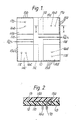
- the dual-band antenna illustrated comprises two crossed slot antennas superimposed on a common ground plane 10.
- the first crossed slot antenna is formed of a set of four patches 11a-11d having effective lengths ⁇ m (1) /4 arranged in rotation so that their radiating edges form the crossed slot structure.
- the patches 11a-11d are copper foil carried on one face of a sheet of dielectric material 12 the other face of which carries the ground plane copper foil 10.
- superimposed on the first antenna is a second dielectric sheet 13 carrying a second set of four copper foil patches 14a-14d, aligned with the first set of patches.
- the patches 14a-14d each have an effective length of ⁇ m (2) /4, where ⁇ m (1) is greater than ⁇ m (2) .
- Both sets of patches are shorted to the ground plane 10 by common sets of shorting pins 15a-15d.
- the patches of the first set are fed by respective coaxial feeds 16a-16d the outer conductors of which are connected to the ground plane.
- the patches of the second set are fed by respective coaxial feeds 17a-17d the outer conductors of which pass through the ground plane and are connected to both the ground plane and the patches of the first set. It is to be noted that the radiating edges of each stacked pair of patches are arranged so that the top patch does not obstruct the radiation from the bottom patch.
- the common shorting plane using either a row of metal pins as illustrated or a continuous metal strip, can be used, having the radiating edges appropriately placed with respect to each other and to the centre lines of the crossed slot. For other frequency separations separate shorting planes might be preferred.
- microstrip substrates with different dielectric constants could be used to alter the relative patch lengths involved (approximately equal to ⁇ m (1) /4 ⁇ 1 and ⁇ m (2) /4 ⁇ 2).
- the lateral dimensions of the antenna are governed by ⁇ m (1) (the larger wavelength) and r (the relative permittivity) of the microstrip substrate.
- the approximate size of the square side of the structure is approximately ⁇ m (1) /2 ⁇ r .
- the exact size is determined by the width chosen for the patches and the "slot" width (i.e. the separation between adjacent patch edges).
- the thickness of the antenna is related to the required bandwidths at the two frequencies f1 and f2.
- very thin substrates With a simple feed probe connected directly to the patch, very thin substrates (height considerably less than patch dimensions) imply bandwiths of a very few per cent. Thicker substrates offer bandwidths approximately 5%-10%, or greater if broadbanding techniques are used.
Landscapes
- Physics & Mathematics (AREA)
- Electromagnetism (AREA)
- Waveguide Aerials (AREA)
- Variable-Direction Aerials And Aerial Arrays (AREA)
Applications Claiming Priority (2)
| Application Number | Priority Date | Filing Date | Title |
|---|---|---|---|
| GB8628599 | 1986-11-29 | ||
| GB8628599A GB2198290B (en) | 1986-11-29 | 1986-11-29 | Dual band circularly polarised antenna with hemispherical coverage |
Publications (2)
| Publication Number | Publication Date |
|---|---|
| EP0270209A2 true EP0270209A2 (de) | 1988-06-08 |
| EP0270209A3 EP0270209A3 (de) | 1990-06-13 |
Family
ID=10608190
Family Applications (1)
| Application Number | Title | Priority Date | Filing Date |
|---|---|---|---|
| EP87307944A Ceased EP0270209A3 (de) | 1986-11-29 | 1987-09-09 | Zirkular polarisierte Antenne für zwei Frequenzbänder mit halbkugelförmiger Richtcharakteristik |
Country Status (4)
| Country | Link |
|---|---|
| US (1) | US4783661A (de) |
| EP (1) | EP0270209A3 (de) |
| JP (1) | JP2590149B2 (de) |
| GB (1) | GB2198290B (de) |
Cited By (10)
| Publication number | Priority date | Publication date | Assignee | Title |
|---|---|---|---|---|
| FR2636780A1 (fr) * | 1988-09-21 | 1990-03-23 | Europ Agence Spatiale | Antenne composite a diplexage a polarisation circulaire |
| EP0408430A1 (de) * | 1989-07-11 | 1991-01-16 | SAT (SOCIETE ANONYME DE TELECOMMUNICATIONS) Société Anonyme française | Antenne mit halbkugelförmigem Strahlungsdiagramm und gegen grosse Hitze widerstandsfähigen Strahlerelementen |
| EP0521384A1 (de) * | 1991-07-01 | 1993-01-07 | Ball Corporation | Schichtartig aufgebaute Mehrfachfrequenz-Streifenleiterantenne |
| US5223848A (en) * | 1988-09-21 | 1993-06-29 | Agence Spatiale Europeenne | Duplexing circularly polarized composite |
| FR2748162A1 (fr) * | 1996-04-24 | 1997-10-31 | Brachat Patrice | Antenne imprimee compacte pour rayonnement a faible elevation |
| US6008764A (en) * | 1997-03-25 | 1999-12-28 | Nokia Mobile Phones Limited | Broadband antenna realized with shorted microstrips |
| EP2159878A1 (de) * | 2008-08-28 | 2010-03-03 | ERA Technology Limited | Schichtartig aufgebaute Patch-Gruppenantenne |
| CN109845035A (zh) * | 2016-10-14 | 2019-06-04 | 松下知识产权经营株式会社 | 天线、无线发送装置以及位置测量系统 |
| TWI766633B (zh) * | 2020-11-18 | 2022-06-01 | 稜研科技股份有限公司 | 寬頻線極化天線結構 |
| US12107336B2 (en) | 2020-11-18 | 2024-10-01 | Tmy Technology Inc. | Broadband linear polarization antenna structure |
Families Citing this family (48)
| Publication number | Priority date | Publication date | Assignee | Title |
|---|---|---|---|---|
| US6181277B1 (en) * | 1987-04-08 | 2001-01-30 | Raytheon Company | Microstrip antenna |
| US4924236A (en) * | 1987-11-03 | 1990-05-08 | Raytheon Company | Patch radiator element with microstrip balian circuit providing double-tuned impedance matching |
| JPH0659009B2 (ja) * | 1988-03-10 | 1994-08-03 | 株式会社豊田中央研究所 | 移動体用アンテナ |
| JP2537390B2 (ja) * | 1988-12-23 | 1996-09-25 | 原田工業株式会社 | プレ―ンアンテナ |
| US4980694A (en) * | 1989-04-14 | 1990-12-25 | Goldstar Products Company, Limited | Portable communication apparatus with folded-slot edge-congruent antenna |
| JPH03263903A (ja) * | 1989-04-28 | 1991-11-25 | Misao Haishi | 小形アンテナ |
| JPH03166803A (ja) * | 1989-11-27 | 1991-07-18 | Kokusai Denshin Denwa Co Ltd <Kdd> | 二周波分離給電円偏波用マイクロストリップアンテナ |
| US5173711A (en) * | 1989-11-27 | 1992-12-22 | Kokusai Denshin Denwa Kabushiki Kaisha | Microstrip antenna for two-frequency separate-feeding type for circularly polarized waves |
| US5406292A (en) * | 1993-06-09 | 1995-04-11 | Ball Corporation | Crossed-slot antenna having infinite balun feed means |
| GB2290416B (en) * | 1994-06-11 | 1998-11-18 | Motorola Israel Ltd | An antenna |
| AU697937B2 (en) * | 1994-06-11 | 1998-10-22 | Motorola Israel Limited | Antenna and method of manufacture of a radio |
| US5502451A (en) * | 1994-07-29 | 1996-03-26 | The United States Of America As Represented By The Secretary Of The Air Force | Patch antenna with magnetically controllable radiation polarization |
| CA2164669C (en) * | 1994-12-28 | 2000-01-18 | Martin Victor Schneider | Multi-branch miniature patch antenna having polarization and share diversity |
| DE19614979C2 (de) | 1995-04-20 | 2001-05-17 | Fujitsu Ltd | Hochfrequenz-Sende-Empfangs-Vorrichtung zur Datenkommunikation |
| US5815119A (en) * | 1996-08-08 | 1998-09-29 | E-Systems, Inc. | Integrated stacked patch antenna polarizer circularly polarized integrated stacked dual-band patch antenna |
| US5703601A (en) * | 1996-09-09 | 1997-12-30 | The United States Of America As Represented By The Secretary Of The Army | Double layer circularly polarized antenna with single feed |
| US5945950A (en) * | 1996-10-18 | 1999-08-31 | Arizona Board Of Regents | Stacked microstrip antenna for wireless communication |
| GB9626763D0 (en) * | 1996-12-23 | 1997-02-12 | Northern Telecom Ltd | Mobile communications handsets |
| US6025816A (en) * | 1996-12-24 | 2000-02-15 | Ericsson Inc. | Antenna system for dual mode satellite/cellular portable phone |
| FI113212B (fi) * | 1997-07-08 | 2004-03-15 | Nokia Corp | Usean taajuusalueen kaksoisresonanssiantennirakenne |
| SE511911C2 (sv) * | 1997-10-01 | 1999-12-13 | Ericsson Telefon Ab L M | Antennenhet med en flerskiktstruktur |
| SE511907C2 (sv) | 1997-10-01 | 1999-12-13 | Ericsson Telefon Ab L M | Integrerad kommunikationsanordning |
| US5969681A (en) * | 1998-06-05 | 1999-10-19 | Ericsson Inc. | Extended bandwidth dual-band patch antenna systems and associated methods of broadband operation |
| AU8034400A (en) | 1999-08-27 | 2001-03-26 | Antennas America, Inc. | Compact planar inverted f antenna |
| AU7999500A (en) * | 1999-10-12 | 2001-04-23 | Arc Wireless Solutions, Inc. | Compact dual narrow band microstrip antenna |
| DE10037386A1 (de) * | 2000-08-01 | 2002-02-14 | Bosch Gmbh Robert | Kombiniertes Empfänger- und Transpondermodul |
| US6984522B2 (en) * | 2000-08-03 | 2006-01-10 | Regents Of The University Of Michigan | Isolation and use of solid tumor stem cells |
| GB2370158B (en) * | 2000-12-13 | 2004-10-13 | Harada Ind | Multiband PIFA-type antenna for vehicular applications |
| US6795021B2 (en) * | 2002-03-01 | 2004-09-21 | Massachusetts Institute Of Technology | Tunable multi-band antenna array |
| US6995709B2 (en) * | 2002-08-19 | 2006-02-07 | Raytheon Company | Compact stacked quarter-wave circularly polarized SDS patch antenna |
| TW200807808A (en) * | 2006-07-21 | 2008-02-01 | Advanced Connectek Inc | An array antenna capable of reducing side lobe level |
| US7633454B2 (en) * | 2006-12-20 | 2009-12-15 | Lockheed Martin Corporation | Antenna array system and method for beamsteering |
| US8384599B2 (en) * | 2009-02-13 | 2013-02-26 | William N. Carr | Multiple-cavity antenna |
| US8284104B2 (en) * | 2009-02-13 | 2012-10-09 | Carr William N | Multiple-resonator antenna |
| US8477079B2 (en) * | 2009-02-13 | 2013-07-02 | William N. Carr | Multiple-cavity antenna |
| US9252500B2 (en) | 2010-01-29 | 2016-02-02 | Orban Microwave Products (Omp), N.V. | Circularly polarized antenna and feeding network |
| US8786497B2 (en) * | 2010-12-01 | 2014-07-22 | King Fahd University Of Petroleum And Minerals | High isolation multiband MIMO antenna system |
| US9099777B1 (en) * | 2011-05-25 | 2015-08-04 | The Boeing Company | Ultra wide band antenna element |
| US9368879B1 (en) | 2011-05-25 | 2016-06-14 | The Boeing Company | Ultra wide band antenna element |
| JP2014027417A (ja) * | 2012-07-25 | 2014-02-06 | Denso Wave Inc | アンテナ |
| US9172147B1 (en) | 2013-02-20 | 2015-10-27 | The Boeing Company | Ultra wide band antenna element |
| GB2528839B (en) * | 2014-07-25 | 2019-04-03 | Kathrein Werke Kg | Multiband antenna |
| US9997844B2 (en) * | 2016-08-15 | 2018-06-12 | Microsoft Technology Licensing, Llc | Contactless millimeter wave coupler, an electronic apparatus and a connector cable |
| KR101921182B1 (ko) * | 2017-07-25 | 2018-11-22 | 엘지전자 주식회사 | 어레이 안테나 및 이동 단말기 |
| WO2021019899A1 (ja) * | 2019-07-29 | 2021-02-04 | 株式会社村田製作所 | アンテナ装置、アンテナモジュールおよび通信装置 |
| WO2021153035A1 (ja) * | 2020-01-30 | 2021-08-05 | 株式会社村田製作所 | アンテナ装置 |
| US20230352837A1 (en) * | 2022-04-28 | 2023-11-02 | City University Of Hong Kong | Patch antenna |
| WO2024106464A1 (ja) * | 2022-11-18 | 2024-05-23 | 京セラ株式会社 | アンテナ |
Family Cites Families (6)
| Publication number | Priority date | Publication date | Assignee | Title |
|---|---|---|---|---|
| US4070676A (en) * | 1975-10-06 | 1978-01-24 | Ball Corporation | Multiple resonance radio frequency microstrip antenna structure |
| US4089003A (en) * | 1977-02-07 | 1978-05-09 | Motorola, Inc. | Multifrequency microstrip antenna |
| US4162499A (en) * | 1977-10-26 | 1979-07-24 | The United States Of America As Represented By The Secretary Of The Army | Flush-mounted piggyback microstrip antenna |
| GB2067842B (en) * | 1980-01-16 | 1983-08-24 | Secr Defence | Microstrip antenna |
| JPS5895407A (ja) * | 1981-12-02 | 1983-06-07 | Nippon Telegr & Teleph Corp <Ntt> | 円錐ビ−ムアレ−アンテナ |
| FR2552938B1 (fr) * | 1983-10-04 | 1986-02-28 | Dassault Electronique | Dispositif rayonnant a structure microruban perfectionnee et application a une antenne adaptative |
-
1986
- 1986-11-29 GB GB8628599A patent/GB2198290B/en not_active Expired - Fee Related
-
1987
- 1987-09-09 EP EP87307944A patent/EP0270209A3/de not_active Ceased
- 1987-09-30 US US07/102,715 patent/US4783661A/en not_active Expired - Lifetime
- 1987-11-26 JP JP62298842A patent/JP2590149B2/ja not_active Expired - Lifetime
Cited By (15)
| Publication number | Priority date | Publication date | Assignee | Title |
|---|---|---|---|---|
| FR2636780A1 (fr) * | 1988-09-21 | 1990-03-23 | Europ Agence Spatiale | Antenne composite a diplexage a polarisation circulaire |
| EP0360692A1 (de) * | 1988-09-21 | 1990-03-28 | Agence Spatiale Europeenne | Zusammengesetzte Duplexantenne mit zirkularer Polarisation |
| US5223848A (en) * | 1988-09-21 | 1993-06-29 | Agence Spatiale Europeenne | Duplexing circularly polarized composite |
| EP0408430A1 (de) * | 1989-07-11 | 1991-01-16 | SAT (SOCIETE ANONYME DE TELECOMMUNICATIONS) Société Anonyme française | Antenne mit halbkugelförmigem Strahlungsdiagramm und gegen grosse Hitze widerstandsfähigen Strahlerelementen |
| FR2649832A1 (fr) * | 1989-07-11 | 1991-01-18 | Telecommunications Sa | Antenne a diagramme de rayonnement quasi hemispherique et a partie rayonnante supportant la chaleur |
| EP0521384A1 (de) * | 1991-07-01 | 1993-01-07 | Ball Corporation | Schichtartig aufgebaute Mehrfachfrequenz-Streifenleiterantenne |
| FR2748162A1 (fr) * | 1996-04-24 | 1997-10-31 | Brachat Patrice | Antenne imprimee compacte pour rayonnement a faible elevation |
| EP0805512A1 (de) * | 1996-04-24 | 1997-11-05 | France Telecom | Kompakt gedruckte Antenne mit geringer Strahlung in Elevationsrichtung |
| US5966096A (en) * | 1996-04-24 | 1999-10-12 | France Telecom | Compact printed antenna for radiation at low elevation |
| US6008764A (en) * | 1997-03-25 | 1999-12-28 | Nokia Mobile Phones Limited | Broadband antenna realized with shorted microstrips |
| EP2159878A1 (de) * | 2008-08-28 | 2010-03-03 | ERA Technology Limited | Schichtartig aufgebaute Patch-Gruppenantenne |
| WO2010023454A1 (en) * | 2008-08-28 | 2010-03-04 | Era Technology Limited | Stacked patch antenna array |
| CN109845035A (zh) * | 2016-10-14 | 2019-06-04 | 松下知识产权经营株式会社 | 天线、无线发送装置以及位置测量系统 |
| TWI766633B (zh) * | 2020-11-18 | 2022-06-01 | 稜研科技股份有限公司 | 寬頻線極化天線結構 |
| US12107336B2 (en) | 2020-11-18 | 2024-10-01 | Tmy Technology Inc. | Broadband linear polarization antenna structure |
Also Published As
| Publication number | Publication date |
|---|---|
| GB2198290B (en) | 1990-05-09 |
| US4783661A (en) | 1988-11-08 |
| JP2590149B2 (ja) | 1997-03-12 |
| GB8628599D0 (en) | 1987-01-07 |
| JPS63144606A (ja) | 1988-06-16 |
| GB2198290A (en) | 1988-06-08 |
| EP0270209A3 (de) | 1990-06-13 |
Similar Documents
| Publication | Publication Date | Title |
|---|---|---|
| US4783661A (en) | Dual-band circularly polarised antenna with hemispherical coverage | |
| US4843400A (en) | Aperture coupled circular polarization antenna | |
| US10826183B2 (en) | Circularly polarized antennas | |
| US3971032A (en) | Dual frequency microstrip antenna structure | |
| EP0954886B1 (de) | Annähernd flaches, aperturgekoppeltes antennenelement | |
| US10381732B2 (en) | Antennas with improved reception of satellite signals | |
| US4847625A (en) | Wideband, aperture-coupled microstrip antenna | |
| US5786793A (en) | Compact antenna for circular polarization | |
| EP0188087B1 (de) | Mikrostreifenleiterantennensystem | |
| US4125838A (en) | Dual asymmetrically fed electric microstrip dipole antennas | |
| US5952971A (en) | Polarimetric dual band radiating element for synthetic aperture radar | |
| EP0105103B1 (de) | Streifenleiter-Antennensystem mit nichtleitender Kopplung | |
| US4087822A (en) | Radio frequency antenna having microstrip feed network and flared radiating aperture | |
| US20040104859A1 (en) | Wide bandwidth flat panel antenna array | |
| US5444452A (en) | Dual frequency antenna | |
| US4870426A (en) | Dual band antenna element | |
| GB2230902A (en) | Antenna element | |
| GB2202379A (en) | Wide band antenna | |
| CN101982900A (zh) | L/s/x三波段双极化平面天线阵 | |
| US20030112200A1 (en) | Horizontally polarized printed circuit antenna array | |
| EP0468413A2 (de) | Ebene Antenne mit hohem Gewinn und grossem Wirkungsgrad | |
| EP1646110B1 (de) | Logarithmisch periodische Mikrostreifengruppenantenne mit geerdetem halbkoplanaren Übergang von Wellenleiter auf Mikrostreifenleitung | |
| US12126078B2 (en) | Omnidirectional horizontally polarized antenna with high current protection | |
| EP0493014A1 (de) | Streifenleitungsantenne | |
| CA2182334C (en) | Mini-cap radiating element |
Legal Events
| Date | Code | Title | Description |
|---|---|---|---|
| PUAI | Public reference made under article 153(3) epc to a published international application that has entered the european phase |
Free format text: ORIGINAL CODE: 0009012 |
|
| AK | Designated contracting states |
Kind code of ref document: A2 Designated state(s): BE DE FR IT NL |
|
| PUAL | Search report despatched |
Free format text: ORIGINAL CODE: 0009013 |
|
| AK | Designated contracting states |
Kind code of ref document: A3 Designated state(s): BE DE FR IT NL |
|
| 17P | Request for examination filed |
Effective date: 19900702 |
|
| 17Q | First examination report despatched |
Effective date: 19920624 |
|
| RAP1 | Party data changed (applicant data changed or rights of an application transferred) |
Owner name: NORTHERN TELECOM LIMITED |
|
| APAB | Appeal dossier modified |
Free format text: ORIGINAL CODE: EPIDOS NOAPE |
|
| STAA | Information on the status of an ep patent application or granted ep patent |
Free format text: STATUS: THE APPLICATION HAS BEEN REFUSED |
|
| 18R | Application refused |
Effective date: 19960707 |
|
| APAF | Appeal reference modified |
Free format text: ORIGINAL CODE: EPIDOSCREFNE |
|
| RIN1 | Information on inventor provided before grant (corrected) |
Inventor name: SMITH, MARTIN STEVENS |