EP0270286B1 - Interrupteur d'alarme - Google Patents
Interrupteur d'alarme Download PDFInfo
- Publication number
- EP0270286B1 EP0270286B1 EP87310268A EP87310268A EP0270286B1 EP 0270286 B1 EP0270286 B1 EP 0270286B1 EP 87310268 A EP87310268 A EP 87310268A EP 87310268 A EP87310268 A EP 87310268A EP 0270286 B1 EP0270286 B1 EP 0270286B1
- Authority
- EP
- European Patent Office
- Prior art keywords
- frangible
- front plate
- switch
- areas
- stop element
- Prior art date
- Legal status (The legal status is an assumption and is not a legal conclusion. Google has not performed a legal analysis and makes no representation as to the accuracy of the status listed.)
- Expired - Lifetime
Links
Images




Classifications
-
- G—PHYSICS
- G08—SIGNALLING
- G08B—SIGNALLING SYSTEMS, e.g. PERSONAL CALLING SYSTEMS; ORDER TELEGRAPHS; ALARM SYSTEMS
- G08B25/00—Alarm systems in which the location of the alarm condition is signalled to a central station, e.g. fire or police telegraphic systems
- G08B25/12—Manually actuated calamity alarm transmitting arrangements emergency non-personal manually actuated alarm, activators, e.g. details of alarm push buttons mounted on an infrastructure
-
- H—ELECTRICITY
- H01—ELECTRIC ELEMENTS
- H01H—ELECTRIC SWITCHES; RELAYS; SELECTORS; EMERGENCY PROTECTIVE DEVICES
- H01H3/00—Mechanisms for operating contacts
- H01H3/02—Operating parts, i.e. for operating driving mechanism by a mechanical force external to the switch
- H01H3/022—Emergency operating parts, e.g. for stop-switch in dangerous conditions
- H01H2003/0233—Emergency operating parts, e.g. for stop-switch in dangerous conditions for alarm triggering, e.g. fire alarm, emergency off switches operated by breaking a glass
-
- H—ELECTRICITY
- H01—ELECTRIC ELEMENTS
- H01H—ELECTRIC SWITCHES; RELAYS; SELECTORS; EMERGENCY PROTECTIVE DEVICES
- H01H2300/00—Orthogonal indexing scheme relating to electric switches, relays, selectors or emergency protective devices covered by H01H
- H01H2300/052—Controlling, signalling or testing correct functioning of a switch
Definitions
- the invention relates to an alarm switch which may typically be used as a fire alarm switch and which is of the kind known as a "manual call point". Such switches are mounted in a wall-mounted box with a front face which has a frangible element. Originally, the frangible element was a glass plate, but more satisfactory alternatives have been developed.
- the specification of DE-C-615839 which has been used to delimit the preamble of claim 1 describes an emergency apparatus having a breakable glass plate with separate frangible areas which may readily be broken.
- the object of the invention is to provide an improved switch of this kind which allows ease of resetting.
- an alarm switch comprising a box for wall-mounting; a front plate for the box; a frangible element which may be broken by pushing the front plate, and a switch unit operated as a result of the movement of the front plate because of the frangible element being broken, the frangible element comprising a plurality of frangible areas which may be broken from it and there being a stop element against which one of these frangible areas bears so that this frangible area is broken off by pressure against the front plate, characterised in that the frangible areas and the stop element are movable relative to each other so that the switch can be reset after use by arranging that the stop element co-operates with the next frangible area.
- said movement is rotary, the frangible areas being distributed around a circle.
- the movement may be linear, with the frangible areas arranged in a line.
- the frangible areas may be arranged on a body which is movable relative to a fixed stop.
- the stop may be movable relative to fixed frangible areas.
- the frangible areas are fixed and form part of the front plate.
- body may thus mean the front plate.
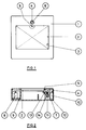
- the switch comprises a box for wall-mounting with a base and a lid 1.
- a transparent front plate 2 of plastics material is situated immediately beneath the lid and is revealed by a central aperture 3 in the lid.
- a frangible element 4 is situated near the top of the box and has a frangible area 5 behind the front plate 2.
- the alarm is operated by pressing the front plate and breaking off the area 5, whereupon a switch is operated in a manner to be described.
- Resetting can be effected by a reset key inserted in the square hole 6 in the element 4.
- the body of the box is shown at 7 and has a micro-switch 8 mounted adjacent an upstanding wall 9 which acts as a pivot for the front plate 2, on which it is supported near one end.
- the other end of the front plate is supported by the frangible area.
- This other end can be regarded as a stop which co-operates with the frangible area 5 of the element 4.
- the micro-switch 8 is held off by the front plate, but when the front plate is pressed to break off the frangible area it pivots to allow the switch contacts to make and operate the alarm.
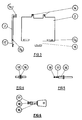
- Figure 2 shows a mounting post 10 on which the element 4 is mounted to be rotatable.
- the post has slots 11 by which is mounted a retraction arm 12 urged downwardly away from element 4 by a spring 13.
- the plate 2 has two dependent brackets, one of which is shown at 14, which embrace the arm 12.
- the arm 12 may be drawn back by a reset key to raise the front plate and reset the switch.
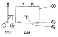
- Figure 3 shows the front plate which has a tongue 15 which operates the micro-switch and indents 9a which co-operate with detents on the top of wall 9.
- the brackets 14 are shown also.
- the reset key has a square shank 16 with a reduced midportion 17 and an end portion 18.
- Figures 7 and 8 show the frangible element 4 as having a body 19 and a square plate 20, the four corners of which are the frangible areas 5.
- the element may be turned by the reset key since the square shank of the key fits the square hole 6 in the element. In this way, when one corner has been broken off the plate 20 by operation of the switch, another corner can be brought into position by turning the element by 90°. The corners are visible through the front plate to show when the switch is armed.
- the dimensions of the element 4 are such that when turned through 45°, a side of the square plate is brought into alignment with the edge of the front plate and the front plate is clear of the frangible plate 20. Thus, the front plate can be moved to operate the switch for testing purposes.
- the retraction arm 12 is shown in Figures 9 and 10 as having a central boss 21 with a star-shaped hole 22. Enlarged areas 23 are provided at the ends of the arm to co-operate with the brackets 14 of the front plate.
- the end portion 18 of the reset key may be inserted into the hole 22 when the key is aligned with or at right-angles to the arm 12 and thus when the element 4 is in the armed position.
- FIG 11 shows an alternative arrangement, where the front plate itself is provided with the frangible areas.
- a projection 23 on the front plate has a hole 24 into which project four frangible teeth 27.
- the front plate is held in the armed position by co-operation of one of the teeth with a stop 25 which is the end of a rotatable arm 26.
- frangible element and stop are reversed with respect to the previously described arrangement.
- frangible areas may be frangible by suitable choice of brittle material - for example plastics, or by local weakening as by reduced thickness or scoring.
- FIG. 12 and 13 there is shown an alternative arrangement for the front plate.
- the microswitch (not shown in Figures 12 and 13) is mounted centrally in the box in this embodiment and on its side with respect to the arrangement of Figure 3 and is operated by the bracket 15a.
- brackets 14 the plate engaging the retraction arm 12 directly in this embodiment. This arrangement allows the unit to be housed in a shallower box.
- the switch comprises a box for wall-mounting with a base 107 and a lid 101.
- a front plate 102 of plastics material which is situated immediately beneath the lid is revealed by a central aperture 103 in the lid.
- a rotatable stop disc 104a with a stop lug 104 is situated beneath a set of frangible teeth 105 which form part of the front plate 102.
- the alarm is operated by pressing the front plate and breaking off a tooth 105 against the lug 104, whereupon a switch is operated in a manner to be described.
- Besetting can be effected by a reset key inserted in the square hole 106 in the element 104a.
- the base of the box is shown at 107 and has a micro-switch 108 which co-operates with a bracket 115a on the front plate.
- the front plate pivots on a wall 109 on which it is supported near one end. The other end of the front plate is supported by the frangible tooth.
- the micro-switch 108 is held in by the front plate, but when the front plate is pressed to break off the frangible tooth it pivots to allow the switch contacts to make (or break) and operate the alarm.
- the front plate has a retraction arm 120 which is moulded integrally in the form of a stirrup including a ring 121 with a square hole 122 ( Figure 16).
- the stop lug 104 has a similar square hole 106.
- a reset key 124 is used to retrieve the front plate and reset the alarm after operation or testing.
- the reset key has a square shank 125 which engages the hole 106, a square end portion 126 which engages the hole 122 and a cylindrical midportion 127.
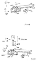
- FIG 16 there is shown a schematic view of the alarm in the armed condition.
- the front plate rests at one end on the wall 109 and at the other end on stop lug 104 by way of a frangible tooth 105.
- the switch 108 is held in.
- Figure 17 shows the condition of the alarm with the front plate having been pressed to operate the alarm. Tooth 105 is broken off against the stop lug 104, so allowing the front plate to drop and the switch 108 to close (or open) to operate the alarm.
- Figures 18 and 19 show the alarm being rearmed.
- the reset key is inserted through the stop disc 104a and the end portion 126 is inserted through hole 122.
- the key is twisted by 45°. This is allowed because of the cylindrical midportion 127.
- the end portion of the key engages the ring 121 and allows the front plate to be drawn back.
- the stop disc 104a has been rotated through 45° and the front plate may be drawn past the lug 104, whereupon further twisting of the key by 45° turns the stop disc to place the lug beneath the next frangible tooth 105 and aligns the end portion 126 with hole 122 so that the key may be withdrawn, the alarm having then been reset, as shown in Figure 19.
- the key may be used to twist the stop disc by 45°, thus allowing the front plate to drop in and close (or open) switch 108. Resetting is accomplished as described above.
Landscapes
- Business, Economics & Management (AREA)
- Emergency Management (AREA)
- Physics & Mathematics (AREA)
- General Physics & Mathematics (AREA)
- Switch Cases, Indication, And Locking (AREA)
Claims (6)
- Interrupteur d'alarme, comprenant un boîtier destiné à être monté sur un mur (1, 7 ; 101, 107), une plaque avant (2 ; 102) du boîtier, un élément cassable (4 ; 23 ; 105) qui peut être cassé par poussée de la plaque avant (2 ; 102), et un ensemble interrupteur (8 ; 108) manoeuvré par le déplacement de la plaque avant (2 ; 102) à la suite de la cassure de l'élément cassable (4 ; 23 ; 105), l'élément cassable (4 ; 23 ; 105) comprenant plusieurs zones cassables (5 ; 27 ; 105) qui peuvent être cassées et un élément d'arrêt (2 ; 25 ; 104) contre lequel l'une des zones cassables est en appui de manière que cette zone cassable soit cassée par une pression appliquée à la plaque avant (2 ; 102), caractérisé en ce que les zones cassables (5 ; 27 ; 105) et l'élément d'arrêt (2 ; 25 ; 104) sont mobiles mutuellement afin que l'interrupteur puisse être réarmé après utilisation par mise en coopération de l'élément d'arrêt (2 ; 25 ; 104) avec la zone cassable suivante (5 ; 27 ; 105).
- Interrupteur d'alarme selon la revendication 1, caractérisé en ce que les zones cassables sont disposées sur un corps fixe, et l'élément d'arrêt est mobile.
- Interrupteur d'alarme selon la revendication 1, caractérisé en ce que les zones cassables (27 ; 105) sont disposées sur la plaque avant (2 ; 102) et l'élément d'arrêt (25 ; 104) est mobile.
- Interrupteur d'alarme selon la revendication 1, caractérisé en ce que les zones cassables sont disposées sur un corps mobile, et l'élément d'arrêt est fixe.
- Interrupteur d'alarme selon l'une quelconque des revendications précédentes, caractérisé en ce que le déplacement relatif des zones cassables (5 ; 27 ; 105) et de l'élément d'arrêt (2 ; 25 ; 104) correspond à une rotation, les zones cassables (5 ; 27 ; 105) étant réparties autour d'un cercle.
- Interrupteur d'alarme selon la revendication 5, caractérisé en ce que la plaque avant porte un bras de recul (12 ; 120) qui lui est fixé et qui a un trou conformé (22 ; 122), et une clé de réarmement est disposée avec une tige (16 ; 125) dont la configuration est telle qu'elle peut coopérer avec un trou conformé (6 ; 106) du corps de l'élément cassable (4) ou de l'élément d'arrêt (104) qui présente le mouvement de rotation, une partie d'extrémité (18 ; 126) dont la configuration permet le passage dans le trou (22 ; 122) du bras de recul (12 ; 12o) et le passage derrière lui lors de la rotation, et une partie médiane (17 ; 127) de dimension réduite permettant la rotation de la clé lorsqu'elle est placée dans le trou (22 ; 122) du bras de recul (12 ; 120).
Priority Applications (1)
| Application Number | Priority Date | Filing Date | Title |
|---|---|---|---|
| AT8787310268T ATE105106T1 (de) | 1986-11-20 | 1987-11-20 | Alarmschalter. |
Applications Claiming Priority (4)
| Application Number | Priority Date | Filing Date | Title |
|---|---|---|---|
| GB8627788 | 1986-11-20 | ||
| GB868627788A GB8627788D0 (en) | 1986-11-20 | 1986-11-20 | Alarm switch |
| GB8713115 | 1987-06-04 | ||
| GB878713115A GB8713115D0 (en) | 1987-06-04 | 1987-06-04 | Alarm switch |
Publications (3)
| Publication Number | Publication Date |
|---|---|
| EP0270286A2 EP0270286A2 (fr) | 1988-06-08 |
| EP0270286A3 EP0270286A3 (en) | 1990-01-17 |
| EP0270286B1 true EP0270286B1 (fr) | 1994-04-27 |
Family
ID=26291560
Family Applications (1)
| Application Number | Title | Priority Date | Filing Date |
|---|---|---|---|
| EP87310268A Expired - Lifetime EP0270286B1 (fr) | 1986-11-20 | 1987-11-20 | Interrupteur d'alarme |
Country Status (5)
| Country | Link |
|---|---|
| US (1) | US4857679A (fr) |
| EP (1) | EP0270286B1 (fr) |
| AU (2) | AU8147187A (fr) |
| CA (1) | CA1292299C (fr) |
| DE (1) | DE3789703T2 (fr) |
Families Citing this family (15)
| Publication number | Priority date | Publication date | Assignee | Title |
|---|---|---|---|---|
| DE3834105C2 (de) * | 1988-10-07 | 1996-09-05 | Gerald Dipl Ing Harms | Notschalter |
| GB2255232A (en) * | 1991-04-23 | 1992-10-28 | Emi Plc Thorn | Alarm call points |
| FR2707784B1 (fr) * | 1993-07-15 | 1995-10-20 | Neutronic | Dispositif déclencheur d'alarme, notamment pour installation de détection d'incendie. |
| GB2283271B (en) * | 1993-10-08 | 1997-02-12 | Pickersgill Kaye Ltd | Emergency cover plate |
| GB2313614A (en) * | 1996-05-31 | 1997-12-03 | Medaes Ltd | Breakable cover for an emergency control device |
| GB2370670B (en) * | 2000-09-22 | 2005-03-02 | Manhar Amlani | Emergency signalling device |
| PT1288881E (pt) * | 2001-09-03 | 2005-09-30 | Siemens Building Tech Ag | Sinalizador manual de emergencia |
| DE102004018269B3 (de) * | 2004-04-15 | 2005-08-11 | Novar Gmbh | Manueller Gefahrenmelder |
| GB2415830B (en) * | 2004-07-01 | 2006-05-17 | Europ Safety Systems Ltd | Call point |
| DE102004042573B3 (de) * | 2004-09-02 | 2005-10-13 | Novar Gmbh | Manueller Gefahrenmelder |
| GB2435546B (en) * | 2006-02-28 | 2009-07-22 | Maxhunt Ltd | Call points |
| GB2441900B (en) * | 2007-09-26 | 2009-03-11 | Gianni Ind Inc | Emergency switch |
| KR101784074B1 (ko) * | 2015-09-03 | 2017-11-06 | 엘지전자 주식회사 | 센싱 장치 |
| CN106548608B (zh) | 2015-09-18 | 2021-06-04 | 海湾安全技术有限公司 | 手拉报警装置推板 |
| RU185715U1 (ru) * | 2018-08-15 | 2018-12-14 | Дмитрий Анатольевич Шильдяев | Извещатель пожарный ручной |
Family Cites Families (7)
| Publication number | Priority date | Publication date | Assignee | Title |
|---|---|---|---|---|
| DE615839C (de) * | 1935-07-15 | Carl Ehinger | OEffentlicher Alarmgeber mit unter einer Glasschutzscheibe angeordnetem Meldekontakt und Fernsprecher sowie einer im Umkreise des Alarmgebergehaeuses befindlichen Alarmglocke | |
| US2822451A (en) * | 1955-12-07 | 1958-02-04 | Willis G Holmes | Alarm sending station |
| US3143611A (en) * | 1962-03-12 | 1964-08-04 | Notifier Corp | Switch operating and resetting mechanism for alarm station |
| US3715743A (en) * | 1970-10-26 | 1973-02-06 | Simplex Time Recorder Co | Fire alarm signalling apparatus |
| GB2078004A (en) * | 1980-06-10 | 1981-12-23 | Ashworth Thomas & Co Ltd | Fire alarms |
| DK188082A (da) * | 1981-04-28 | 1982-10-29 | Tann Synchronome Ltd | Mekanisk aktiveret signalleringsapparat |
| AU1577783A (en) * | 1983-06-15 | 1984-12-20 | Emhart Industries Inc. | Fire alarm switch box |
-
1987
- 1987-11-19 CA CA000552203A patent/CA1292299C/fr not_active Expired - Lifetime
- 1987-11-19 US US07/135,297 patent/US4857679A/en not_active Expired - Lifetime
- 1987-11-20 AU AU81471/87A patent/AU8147187A/en not_active Abandoned
- 1987-11-20 DE DE3789703T patent/DE3789703T2/de not_active Expired - Fee Related
- 1987-11-20 EP EP87310268A patent/EP0270286B1/fr not_active Expired - Lifetime
-
1991
- 1991-08-22 AU AU82668/91A patent/AU631752B2/en not_active Ceased
Also Published As
| Publication number | Publication date |
|---|---|
| CA1292299C (fr) | 1991-11-19 |
| AU8266891A (en) | 1991-10-24 |
| AU8147187A (en) | 1988-05-26 |
| EP0270286A3 (en) | 1990-01-17 |
| DE3789703T2 (de) | 1994-08-11 |
| US4857679A (en) | 1989-08-15 |
| EP0270286A2 (fr) | 1988-06-08 |
| DE3789703D1 (de) | 1994-06-01 |
| AU631752B2 (en) | 1992-12-03 |
Similar Documents
| Publication | Publication Date | Title |
|---|---|---|
| EP0270286B1 (fr) | Interrupteur d'alarme | |
| EP1203361B1 (fr) | Points d'appels ou unites a bris de glace | |
| US3629530A (en) | An electric safety switch apparatus | |
| AU2002300262B2 (en) | Manual Call Point | |
| US5311161A (en) | Molded case circuit breaker motor operator interface assembly | |
| US8443639B2 (en) | Resistant mechanical combination lock and improvements thereto | |
| EP1503390A2 (fr) | Interrupteur d'alarme | |
| CZ20011076A3 (cs) | Dveřní terminál se skříňkou | |
| CN222600884U (zh) | 辅助自锁结构和断路器 | |
| EP0592925A1 (fr) | Avertisseur manuel de risques | |
| GB2255232A (en) | Alarm call points | |
| CN213242434U (zh) | 开关电器的指示装置 | |
| JPS5824362Y2 (ja) | 回路しや断器用警報スイツチ | |
| GB2366450A (en) | A re-armable tripping device | |
| US5219066A (en) | Wall mounted alarm switch with adjustable height actuator | |
| CN220963181U (zh) | 附件集成模块及断路器 | |
| CN222530254U (zh) | 一种防止误操作危险的定时开关防护装置 | |
| CN113327824A (zh) | 剩余电流动作断路器操作机构和剩余电流动作断路器 | |
| CA1305991C (fr) | Commutateur rotatif commandant au moins deux elements de controle | |
| US2703830A (en) | Plug and receptacle construction | |
| JPH0119294Y2 (fr) | ||
| JPH0643968Y2 (ja) | 鍵付き押釦スイッチのロック機構 | |
| JPS646923Y2 (fr) | ||
| US3280279A (en) | Alarm signal device for openable closures | |
| EP0704873A1 (fr) | Interrupteur |
Legal Events
| Date | Code | Title | Description |
|---|---|---|---|
| PUAI | Public reference made under article 153(3) epc to a published international application that has entered the european phase |
Free format text: ORIGINAL CODE: 0009012 |
|
| AK | Designated contracting states |
Kind code of ref document: A2 Designated state(s): AT BE CH DE ES FR GB GR IT LI LU NL SE |
|
| PUAL | Search report despatched |
Free format text: ORIGINAL CODE: 0009013 |
|
| AK | Designated contracting states |
Kind code of ref document: A3 Designated state(s): AT BE CH DE ES FR GB GR IT LI LU NL SE |
|
| 17P | Request for examination filed |
Effective date: 19900727 |
|
| 17Q | First examination report despatched |
Effective date: 19920323 |
|
| GRAA | (expected) grant |
Free format text: ORIGINAL CODE: 0009210 |
|
| RAP1 | Party data changed (applicant data changed or rights of an application transferred) |
Owner name: SIGNATURE INDUSTRIES LIMITED |
|
| AK | Designated contracting states |
Kind code of ref document: B1 Designated state(s): AT BE CH DE ES FR GB GR IT LI LU NL SE |
|
| PG25 | Lapsed in a contracting state [announced via postgrant information from national office to epo] |
Ref country code: IT Free format text: LAPSE BECAUSE OF FAILURE TO SUBMIT A TRANSLATION OF THE DESCRIPTION OR TO PAY THE FEE WITHIN THE PRESCRIBED TIME-LIMIT;WARNING: LAPSES OF ITALIAN PATENTS WITH EFFECTIVE DATE BEFORE 2007 MAY HAVE OCCURRED AT ANY TIME BEFORE 2007. THE CORRECT EFFECTIVE DATE MAY BE DIFFERENT FROM THE ONE RECORDED. Effective date: 19940427 Ref country code: CH Effective date: 19940427 Ref country code: NL Effective date: 19940427 Ref country code: LI Effective date: 19940427 Ref country code: AT Effective date: 19940427 Ref country code: GR Free format text: LAPSE BECAUSE OF FAILURE TO SUBMIT A TRANSLATION OF THE DESCRIPTION OR TO PAY THE FEE WITHIN THE PRESCRIBED TIME-LIMIT Effective date: 19940427 Ref country code: BE Effective date: 19940427 Ref country code: SE Free format text: THE PATENT HAS BEEN ANNULLED BY A DECISION OF A NATIONAL AUTHORITY Effective date: 19940427 |
|
| REF | Corresponds to: |
Ref document number: 105106 Country of ref document: AT Date of ref document: 19940515 Kind code of ref document: T |
|
| REF | Corresponds to: |
Ref document number: 3789703 Country of ref document: DE Date of ref document: 19940601 |
|
| ET | Fr: translation filed | ||
| REG | Reference to a national code |
Ref country code: CH Ref legal event code: PL |
|
| PG25 | Lapsed in a contracting state [announced via postgrant information from national office to epo] |
Ref country code: ES Free format text: LAPSE BECAUSE OF FAILURE TO SUBMIT A TRANSLATION OF THE DESCRIPTION OR TO PAY THE FEE WITHIN THE PRESCRIBED TIME-LIMIT Effective date: 19940807 |
|
| NLV1 | Nl: lapsed or annulled due to failure to fulfill the requirements of art. 29p and 29m of the patents act | ||
| PG25 | Lapsed in a contracting state [announced via postgrant information from national office to epo] |
Ref country code: LU Free format text: LAPSE BECAUSE OF NON-PAYMENT OF DUE FEES Effective date: 19941130 |
|
| PLBE | No opposition filed within time limit |
Free format text: ORIGINAL CODE: 0009261 |
|
| STAA | Information on the status of an ep patent application or granted ep patent |
Free format text: STATUS: NO OPPOSITION FILED WITHIN TIME LIMIT |
|
| 26N | No opposition filed | ||
| PGFP | Annual fee paid to national office [announced via postgrant information from national office to epo] |
Ref country code: GB Payment date: 19971013 Year of fee payment: 11 |
|
| PGFP | Annual fee paid to national office [announced via postgrant information from national office to epo] |
Ref country code: DE Payment date: 19971127 Year of fee payment: 11 |
|
| PG25 | Lapsed in a contracting state [announced via postgrant information from national office to epo] |
Ref country code: GB Free format text: LAPSE BECAUSE OF NON-PAYMENT OF DUE FEES Effective date: 19981120 |
|
| GBPC | Gb: european patent ceased through non-payment of renewal fee |
Effective date: 19981120 |
|
| PG25 | Lapsed in a contracting state [announced via postgrant information from national office to epo] |
Ref country code: DE Free format text: LAPSE BECAUSE OF NON-PAYMENT OF DUE FEES Effective date: 19990901 |
|
| PGFP | Annual fee paid to national office [announced via postgrant information from national office to epo] |
Ref country code: FR Payment date: 20011129 Year of fee payment: 15 |
|
| PG25 | Lapsed in a contracting state [announced via postgrant information from national office to epo] |
Ref country code: FR Free format text: LAPSE BECAUSE OF NON-PAYMENT OF DUE FEES Effective date: 20030731 |
|
| REG | Reference to a national code |
Ref country code: FR Ref legal event code: ST |