EP0270401A1 - Trägergeschoss zum Abwerfen von Tochtergeschossen in kontrollierter Weise - Google Patents
Trägergeschoss zum Abwerfen von Tochtergeschossen in kontrollierter Weise Download PDFInfo
- Publication number
- EP0270401A1 EP0270401A1 EP87402418A EP87402418A EP0270401A1 EP 0270401 A1 EP0270401 A1 EP 0270401A1 EP 87402418 A EP87402418 A EP 87402418A EP 87402418 A EP87402418 A EP 87402418A EP 0270401 A1 EP0270401 A1 EP 0270401A1
- Authority
- EP
- European Patent Office
- Prior art keywords
- sub
- projectiles
- projectile
- projectile according
- ejection
- Prior art date
- Legal status (The legal status is an assumption and is not a legal conclusion. Google has not performed a legal analysis and makes no representation as to the accuracy of the status listed.)
- Granted
Links
- 239000000463 material Substances 0.000 claims abstract description 9
- 239000000126 substance Substances 0.000 claims description 3
- 230000008520 organization Effects 0.000 description 2
- 238000000926 separation method Methods 0.000 description 2
- 239000000470 constituent Substances 0.000 description 1
- 238000010586 diagram Methods 0.000 description 1
- 238000002474 experimental method Methods 0.000 description 1
- 239000002360 explosive Substances 0.000 description 1
- 239000004033 plastic Substances 0.000 description 1
- 239000002984 plastic foam Substances 0.000 description 1
- 239000000843 powder Substances 0.000 description 1
- 239000003380 propellant Substances 0.000 description 1
Images

Classifications
-
- F—MECHANICAL ENGINEERING; LIGHTING; HEATING; WEAPONS; BLASTING
- F42—AMMUNITION; BLASTING
- F42B—EXPLOSIVE CHARGES, e.g. FOR BLASTING, FIREWORKS, AMMUNITION
- F42B12/00—Projectiles, missiles or mines characterised by the warhead, the intended effect, or the material
- F42B12/02—Projectiles, missiles or mines characterised by the warhead, the intended effect, or the material characterised by the warhead or the intended effect
- F42B12/36—Projectiles, missiles or mines characterised by the warhead, the intended effect, or the material characterised by the warhead or the intended effect for dispensing materials; for producing chemical or physical reaction; for signalling ; for transmitting information
- F42B12/56—Projectiles, missiles or mines characterised by the warhead, the intended effect, or the material characterised by the warhead or the intended effect for dispensing materials; for producing chemical or physical reaction; for signalling ; for transmitting information for dispensing discrete solid bodies
- F42B12/58—Cluster or cargo ammunition, i.e. projectiles containing one or more submissiles
- F42B12/62—Cluster or cargo ammunition, i.e. projectiles containing one or more submissiles the submissiles being ejected parallel to the longitudinal axis of the projectile
-
- Y—GENERAL TAGGING OF NEW TECHNOLOGICAL DEVELOPMENTS; GENERAL TAGGING OF CROSS-SECTIONAL TECHNOLOGIES SPANNING OVER SEVERAL SECTIONS OF THE IPC; TECHNICAL SUBJECTS COVERED BY FORMER USPC CROSS-REFERENCE ART COLLECTIONS [XRACs] AND DIGESTS
- Y10—TECHNICAL SUBJECTS COVERED BY FORMER USPC
- Y10S—TECHNICAL SUBJECTS COVERED BY FORMER USPC CROSS-REFERENCE ART COLLECTIONS [XRACs] AND DIGESTS
- Y10S102/00—Ammunition and explosives
- Y10S102/703—Flechette
Definitions
- the present invention relates to a projectile forming the head of a vector, such as a bomb, missile, etc., such a vector possibly comprising a propellant and being provided with a tail unit or a guidance or piloting system, so to have a defined ballistic trajectory.
- a vector such as a bomb, missile, etc.
- a vector possibly comprising a propellant and being provided with a tail unit or a guidance or piloting system, so to have a defined ballistic trajectory.
- the present invention relates to a projectile comprising sub-projectiles ejected at a given time on the trajectory of the carrier projectile, in a controlled direction.
- main projectile carrying sub-charges (or sub-projectiles) to be distributed over large surfaces or volumes.
- sub-projectiles or sub-projectiles
- special precautions are not usually taken for the organization of the sub-projectiles inside the main projectile; this results in a random distribution and orientation of the sub-projectiles during the dropping or, at least, a significant lack of precision on the speed and attitude of the sub-projectiles; the result is that only a portion, which is sometimes small, of the sub-projectiles reaches its goal, the rest being lost.
- the present invention aims to allow to drop sub-projectiles in a preferred direction with satisfactory control of their attitude, so that is not disturbed their subsequent ballistic behavior.
- the subject of the invention is a projectile comprising sub-projectiles, each of these having a fixed tail, for example with three fins; money- projectiles are stored in a single orientation (head forward and tail towards the rear of the main projectile) in one or more rows.
- the bodies of the sub-projectiles are tangent to each other, the empennages being placed one inside the other in a self-locking manner.
- the projectile also includes wedging elements between the body of the main projectile and the structure formed by the sub-projectiles.
- the projectile comprises additional wedging elements disposed between the different sub-projectiles of the same row.
- the spaces which remain free between the sub-projectiles and the wedging elements are filled with a pulverulent substance which has the function of improving the rigidity of the assembly and, when the projectile comprises several rows of sub-projectiles, ensure and maintain a spacing between the layers.
- the invention relates to a projectile as defined by claim 1.
- This projectile with a longitudinal axis XX, is generally identified 1 and consists of a cylindrical envelope 3, ending on one side by a warhead 2 of aerodynamic shape, for example substantially conical; at the other end, the projectile is fixed on the rest of the vector, represented by dotted lines 30.
- sub-projectiles 5 Inside the envelope 3 are longitudinally disposed sub-projectiles 5. Each of them consists of a cylindrical body 54 terminating towards the front by an aerodynamic head 55, for example substantially conical, and of the 'other side by a tail 56, allowing it to maintain a given attitude on a given trajectory.
- the sub-projectiles 5 are arranged in the projectile in one or, as in the case of FIG. 1, several rows, marked 71, 72 and 73. They are disposed there with a unique orientation, namely their head 55 directed towards the front of the projectile.
- Sub-projectiles can be of the explosive ammunition, fireworks (infrared or illuminating) type, lure or kinetic energy munition.
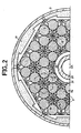
- FIG. 2 is a cross-sectional view of one half of the projectile 1 of FIG. 1, at the level of the tail of the sub-projectiles of one of the rows 71, 72 or 73.
- the outer casing 3 is illustrated and, towards the center, an axis 20 supporting the warhead 2 and an inner casing 31.
- the axis 20 of the warhead is movable in the casing 31 to allow the ejection of the warhead, as described below. All of the sub-projectiles 5 are disposed between the envelopes 3 and 31.
- each of the sub-projectiles 5 and their tail unit 56 has also been shown, the elements 54 and 56 being hatched for the clarity of the drawing.
- the tail of each sub-projectile 5 consists of three fins, arranged at 120 °.
- the bodies 54 of the sub-projectiles are arranged in a hexagon, one of which example is shown in dotted lines 74, the center of the bodies 54 forming the vertices of the hexagon and the bodies 54 being tangent to each other.
- the fins are arranged one inside the other so that the structure formed by all of the sub-projectiles is self-locking, that is to say that in the center of hexagon 74 there are six fins belonging respectively to the six sub-projectiles 5 of the hexagon, blocked one inside the other.
- wedging elements 82 between the sub-projectiles 5, at the level of the bodies 54.
- These elements 82 are for example of substantially cylindrical shape and extend over the entire length of the bodies 54, or only on part of them. For the clarity of FIG. 2, the surface of the elements 82 is dotted.
- These internal wedging elements 82 have the function of improving the rigidity of all of the sub-projectiles 5, in particular in the case where the projectile is rotated around its longitudinal axis.
- the wedging elements 82 are made of a flexible material, such as plastic foam, pre-stressed so as to make it possible to make up for any play in the structure.
- truncated wedging elements marked 83, again with the aim of improving the rigidity of the structure.
- wedging elements marked 81, having the function of preventing any tilting towards the outside of the sub-projectiles 5.
- These elements 81 have a shape adapted to the free space between the structure formed by the sub-projectiles and the outer envelope 3. They are not necessarily of constant section, as illustrated in FIG. 2; however, in a preferred embodiment, they are in contact with the envelope 3 and with the sub-projectiles 5. They are by example made of a plastic material and are preferably made of a relatively rigid material and capable of breaking up during the ejection of the sub-projectiles, according to a mechanism described below, so as not to disturb this ejection.
- the spaces left free between the walls 31 and 3 by the sub-projectiles 5 and the wedging elements 81, 82 or 83, are filled with a pulverulent material 9 whose function is, on the one hand, to improve immobilization of the sub-projectiles 5 in the casing 3 and, on the other hand, ensuring a separation between each of the rows 71, 72 and 73 (see FIG. 1) for a reason linked to the ejection of the sub-projectiles projectiles, as described below.
- This powder 9 also makes it possible to visualize the point of release of the sub-projectiles, which facilitates its use.
- the projectile 1 (FIG. 1) also includes a disc 6 closing the space between the envelopes 3 and 31 at the rear of the loading of sub-projectiles, actuated by propulsion means 4 when the sub-projectiles are dropped.
- FIGS. 3, a and b are diagrams illustrating the mechanism for ejecting the sub-projectiles from the main projectile 1.
- a first step under the action of the propulsion means 4 shown diagrammatically at the rear of the projectile 1, the axis 20 of the warhead 2 slides inside the casing 31 until the warhead separates from the projectile. This is designed so that it then remains stable and does not interfere with the movement of the sub-projectiles being ejected or that of the main projectile.
- the propulsion means 4 impart a relative forward movement to the disc 6 relative to the casing 3, leading to the successive ejection of the rows 71, 72 and 73 of sub-projectiles 5.
- the wedging elements 81-83 and the pulverulent material 9 separates from the sub-projectiles as they appear at the edge of the envelope 3.
- FIG. 3a shows the moment when the warhead 2 is fully ejected from the casing 3 and when the first of the rows, namely row 71, is also fully ejected.
- each of the sub-projectiles 5 is animated at its exit from the envelope 3, in addition to a relative longitudinal speed, a radial speed often called expansion speed, due to the aerodynamic force which is exerted on them at the exit of the envelope 3 and, if necessary, at the rotation of the main projectile. Furthermore, each of the rows is, when it leaves, slowed down by this aerodynamic force. The two phenomena combined make it possible to obtain an interpenetration of the different rows, as shown in FIG. 3b where the three rows being fully ejected, the different sub-projectiles 5 are found substantially on the same line 74 to form a single sheaf, animated by 'a longitudinal speed and a radial speed of expansion.
- the speed of expansion depends on the speed of rotation of the projectile 1, on the dimensioning of the setting elements as well as on the geometrical characteristics of the sub-projectiles and their position relative to the longitudinal axis (XX) of the projectile.
- the applicant's experiments and calculations have shown that it is then important that the heads of the sub-projectiles of a row are without mechanical contact with the rear of the sub-projectiles of the previous row, to avoid that the sub-projectile from behind does not disturb and tilts the sub-projectile from the front.
- the spacing between the rows must be sufficient for the inter-penetration of the rows to be carried out correctly, without contact (or at least with a minimum of contact) between sub-projectiles. This separation function is fulfilled, as indicated above, by the pulverulent material 9.
- the sub-projectiles are rigidly held in place before ejection so as, at the time of ejection, to be able to follow the planned trajectory.
- means are provided so that, during this ejection, the trajectory of each of the sub-projectiles is neither disturbed by the various constituents of the main projectile, nor by the other sub-projectiles.
- the main projectile has been described as having a cylindrical body with a circular section, but this section may have other shapes, for example square, the sub-projectiles then being provided with four fins. More generally, other geometric shapes can be used for the body of the projectile, the body and the tail of the sub-projectiles and their organization (in hexagon in FIG. 2), provided that the bodies of the sub-projectiles are tangent and their tailplane organized in a self-locking manner.
Landscapes
- Engineering & Computer Science (AREA)
- Chemical & Material Sciences (AREA)
- Combustion & Propulsion (AREA)
- General Engineering & Computer Science (AREA)
- Aiming, Guidance, Guns With A Light Source, Armor, Camouflage, And Targets (AREA)
- Toys (AREA)
Applications Claiming Priority (2)
| Application Number | Priority Date | Filing Date | Title |
|---|---|---|---|
| FR8615236A FR2606135B1 (fr) | 1986-10-31 | 1986-10-31 | Projectile comportant des sous-projectiles a largage directionnel controle |
| FR8615236 | 1986-10-31 |
Publications (2)
| Publication Number | Publication Date |
|---|---|
| EP0270401A1 true EP0270401A1 (de) | 1988-06-08 |
| EP0270401B1 EP0270401B1 (de) | 1991-09-04 |
Family
ID=9340429
Family Applications (1)
| Application Number | Title | Priority Date | Filing Date |
|---|---|---|---|
| EP87402418A Expired - Lifetime EP0270401B1 (de) | 1986-10-31 | 1987-10-27 | Trägergeschoss zum Abwerfen von Tochtergeschossen in kontrollierter Weise |
Country Status (6)
| Country | Link |
|---|---|
| US (1) | US4777882A (de) |
| EP (1) | EP0270401B1 (de) |
| BR (1) | BR8705785A (de) |
| CA (1) | CA1316395C (de) |
| DE (1) | DE3772722D1 (de) |
| FR (1) | FR2606135B1 (de) |
Cited By (13)
| Publication number | Priority date | Publication date | Assignee | Title |
|---|---|---|---|---|
| EP0346214A1 (de) * | 1988-06-10 | 1989-12-13 | Thomson-Brandt Armements | Verfahren und Vorrichtung zum Auswerfen von Submunition |
| RU2138763C1 (ru) * | 1998-07-06 | 1999-09-27 | Государственное научно-производственное предприятие "Сплав" | Кассетная боевая часть реактивного снаряда |
| RU2231744C1 (ru) * | 2003-07-08 | 2004-06-27 | Федеральное государственное унитарное предприятие "Государственное научно-производственное предприятие "Базальт" | Парашютный контейнер кассетного боеприпаса |
| US6779462B2 (en) * | 2001-06-04 | 2004-08-24 | Raytheon Company | Kinetic energy rod warhead with optimal penetrators |
| US6910423B2 (en) | 2001-08-23 | 2005-06-28 | Raytheon Company | Kinetic energy rod warhead with lower deployment angles |
| US6920827B2 (en) | 2003-10-31 | 2005-07-26 | Raytheon Company | Vehicle-borne system and method for countering an incoming threat |
| US6931994B2 (en) | 2002-08-29 | 2005-08-23 | Raytheon Company | Tandem warhead |
| US6973878B2 (en) | 2001-06-04 | 2005-12-13 | Raytheon Company | Warhead with aligned projectiles |
| US7017496B2 (en) | 2002-08-29 | 2006-03-28 | Raytheon Company | Kinetic energy rod warhead with imploding charge for isotropic firing of the penetrators |
| US7412916B2 (en) | 2002-08-29 | 2008-08-19 | Raytheon Company | Fixed deployed net for hit-to-kill vehicle |
| US7621222B2 (en) | 2001-08-23 | 2009-11-24 | Raytheon Company | Kinetic energy rod warhead with lower deployment angles |
| US7624682B2 (en) | 2001-08-23 | 2009-12-01 | Raytheon Company | Kinetic energy rod warhead with lower deployment angles |
| US7624683B2 (en) | 2001-08-23 | 2009-12-01 | Raytheon Company | Kinetic energy rod warhead with projectile spacing |
Families Citing this family (34)
| Publication number | Priority date | Publication date | Assignee | Title |
|---|---|---|---|---|
| FR2747770B1 (fr) * | 1989-08-01 | 1998-12-18 | Thomson Brandt Armements | Procede et dispositif d'elaboration de commande d'ejection des sous-munitions portees par une munition air-sol de type cargo |
| DE4026813C1 (de) * | 1990-08-24 | 1996-09-26 | Rheinmetall Ind Gmbh | Flugkörper zur Bekämpfung eines Hubschraubers |
| CH690309A5 (de) * | 1995-04-05 | 2000-07-14 | Contraves Pyrotec Ag | Verfahren und Vorrichtung zur Durchführung des Verfahrens für das Auffüllen von Geschosskörpern mit Subprojektilen. |
| US6024021A (en) * | 1998-04-20 | 2000-02-15 | Schultz; Steven L. | Fragmenting bullet |
| RU2149344C1 (ru) * | 1999-04-07 | 2000-05-20 | Таланов Борис Петрович | Головная часть снаряда |
| US6401591B1 (en) | 2001-01-04 | 2002-06-11 | The United States Of America As Represented By The Secretary Of The Navy | Neutralization chemical injection penetrator |
| US6874425B1 (en) * | 2001-05-18 | 2005-04-05 | Day & Zimmermann, Inc. | Projectile carrying sub-munitions |
| US8127686B2 (en) | 2001-08-23 | 2012-03-06 | Raytheon Company | Kinetic energy rod warhead with aiming mechanism |
| US20040055498A1 (en) * | 2002-08-29 | 2004-03-25 | Lloyd Richard M. | Kinetic energy rod warhead deployment system |
| US20060021538A1 (en) * | 2002-08-29 | 2006-02-02 | Lloyd Richard M | Kinetic energy rod warhead deployment system |
| US7530315B2 (en) | 2003-05-08 | 2009-05-12 | Lone Star Ip Holdings, Lp | Weapon and weapon system employing the same |
| WO2005026654A2 (en) * | 2003-05-08 | 2005-03-24 | Incucomm, Inc. | Weapon and weapon system employing the same |
| EP1737728A4 (de) | 2003-10-14 | 2009-07-08 | Raytheon Co | Minenzählermesssystem |
| US20090320711A1 (en) | 2004-11-29 | 2009-12-31 | Lloyd Richard M | Munition |
| US7895946B2 (en) | 2005-09-30 | 2011-03-01 | Lone Star Ip Holdings, Lp | Small smart weapon and weapon system employing the same |
| US7690304B2 (en) | 2005-09-30 | 2010-04-06 | Lone Star Ip Holdings, Lp | Small smart weapon and weapon system employing the same |
| US7261039B1 (en) * | 2006-04-07 | 2007-08-28 | The United States Of America As Represented By The Secretary Of The Army | Artillery Rocket Kinetic Energy Rod Warhead |
| US8541724B2 (en) | 2006-09-29 | 2013-09-24 | Lone Star Ip Holdings, Lp | Small smart weapon and weapon system employing the same |
| US8117955B2 (en) | 2006-10-26 | 2012-02-21 | Lone Star Ip Holdings, Lp | Weapon interface system and delivery platform employing the same |
| US8485099B2 (en) | 2008-07-10 | 2013-07-16 | Nammo Talley, Inc. | Mine defeat system and pyrotechnic dart for same |
| US8536500B2 (en) * | 2008-08-07 | 2013-09-17 | Cpi Ip, Llc | System and method for rapid aiming and firing of defensive countermeasures |
| US9068807B1 (en) * | 2009-10-29 | 2015-06-30 | Lockheed Martin Corporation | Rocket-propelled grenade |
| US8418623B2 (en) | 2010-04-02 | 2013-04-16 | Raytheon Company | Multi-point time spacing kinetic energy rod warhead and system |
| RU2435130C1 (ru) * | 2010-06-22 | 2011-11-27 | Федеральное Государственное унитарное предприятие "Государственное научно-производственное предприятие "Сплав" | Реактивный снаряд с кассетной головной частью |
| US9140528B1 (en) | 2010-11-16 | 2015-09-22 | Lockheed Martin Corporation | Covert taggant dispersing grenade |
| US9068803B2 (en) | 2011-04-19 | 2015-06-30 | Lone Star Ip Holdings, Lp | Weapon and weapon system employing the same |
| US8640623B2 (en) * | 2011-04-22 | 2014-02-04 | Donald B. Eckstein | Multiple purpose tandem nested projectile |
| US8640622B2 (en) * | 2011-04-22 | 2014-02-04 | Donald B. Eckstein | Tandem nested projectile assembly |
| US9423222B1 (en) | 2013-03-14 | 2016-08-23 | Lockheed Martin Corporation | Less-than-lethal cartridge |
| US9354027B2 (en) | 2013-10-24 | 2016-05-31 | G2 Research Inc. | Fragmenting projectile |
| US9200876B1 (en) | 2014-03-06 | 2015-12-01 | Lockheed Martin Corporation | Multiple-charge cartridge |
| US10663271B2 (en) | 2016-10-13 | 2020-05-26 | G2 Research Inc. | Predictably fragmenting projectiles having internally-arranged geometric features |
| US10690464B2 (en) | 2017-04-28 | 2020-06-23 | Vista Outdoor Operations Llc | Cartridge with combined effects projectile |
| FR3100610B1 (fr) * | 2019-09-06 | 2023-11-03 | Cta Int | Obus anti-aérien pour munition télescopée à double déverrouillage |
Citations (6)
| Publication number | Priority date | Publication date | Assignee | Title |
|---|---|---|---|---|
| DE199366C (de) * | ||||
| US1340871A (en) * | 1917-06-21 | 1920-05-25 | Vickers Ltd | Explosive shell |
| FR621608A (fr) * | 1925-09-19 | 1927-05-14 | Shrapnell avec projectiles fuselés pourvus d'un empennage | |
| US2809583A (en) * | 1952-12-04 | 1957-10-15 | Roman L Ortynsky | Cluster bomb |
| US3088404A (en) * | 1956-11-15 | 1963-05-07 | Brown Fred | Interlocking screw threads |
| US4430941A (en) * | 1968-05-27 | 1984-02-14 | Fmc Corporation | Projectile with supported missiles |
Family Cites Families (6)
| Publication number | Priority date | Publication date | Assignee | Title |
|---|---|---|---|---|
| DE314680C (de) * | ||||
| DE199368C (de) * | 1900-01-01 | |||
| US3599568A (en) * | 1965-03-31 | 1971-08-17 | Olin Mathieson | Long-range shotshell |
| US3903804A (en) * | 1965-09-27 | 1975-09-09 | Us Navy | Rocket-propelled cluster weapon |
| US3673047A (en) * | 1970-09-03 | 1972-06-27 | Us Navy | Flechette assembly machine |
| US3881416A (en) * | 1973-04-23 | 1975-05-06 | Us Army | Choked flechette weapon system |
-
1986
- 1986-10-31 FR FR8615236A patent/FR2606135B1/fr not_active Expired - Fee Related
-
1987
- 1987-07-08 US US07/070,979 patent/US4777882A/en not_active Expired - Lifetime
- 1987-10-27 DE DE8787402418T patent/DE3772722D1/de not_active Expired - Fee Related
- 1987-10-27 EP EP87402418A patent/EP0270401B1/de not_active Expired - Lifetime
- 1987-10-29 BR BR8705785A patent/BR8705785A/pt unknown
- 1987-10-29 CA CA000550590A patent/CA1316395C/fr not_active Expired - Fee Related
Patent Citations (6)
| Publication number | Priority date | Publication date | Assignee | Title |
|---|---|---|---|---|
| DE199366C (de) * | ||||
| US1340871A (en) * | 1917-06-21 | 1920-05-25 | Vickers Ltd | Explosive shell |
| FR621608A (fr) * | 1925-09-19 | 1927-05-14 | Shrapnell avec projectiles fuselés pourvus d'un empennage | |
| US2809583A (en) * | 1952-12-04 | 1957-10-15 | Roman L Ortynsky | Cluster bomb |
| US3088404A (en) * | 1956-11-15 | 1963-05-07 | Brown Fred | Interlocking screw threads |
| US4430941A (en) * | 1968-05-27 | 1984-02-14 | Fmc Corporation | Projectile with supported missiles |
Cited By (18)
| Publication number | Priority date | Publication date | Assignee | Title |
|---|---|---|---|---|
| EP0346214A1 (de) * | 1988-06-10 | 1989-12-13 | Thomson-Brandt Armements | Verfahren und Vorrichtung zum Auswerfen von Submunition |
| FR2632721A1 (fr) * | 1988-06-10 | 1989-12-15 | Thomson Brandt Armements | Procede d'ejection de sous-munitions et projectile mettant en oeuvre un tel procede |
| US5005483A (en) * | 1988-06-10 | 1991-04-09 | Thomson-Brandt Armements | Method for the ejection of sub-munitions and projectile applying said method |
| RU2138763C1 (ru) * | 1998-07-06 | 1999-09-27 | Государственное научно-производственное предприятие "Сплав" | Кассетная боевая часть реактивного снаряда |
| US6779462B2 (en) * | 2001-06-04 | 2004-08-24 | Raytheon Company | Kinetic energy rod warhead with optimal penetrators |
| US6973878B2 (en) | 2001-06-04 | 2005-12-13 | Raytheon Company | Warhead with aligned projectiles |
| JP2008261627A (ja) * | 2001-06-04 | 2008-10-30 | Raytheon Co | 複数の発射体が整列される弾頭 |
| US7624683B2 (en) | 2001-08-23 | 2009-12-01 | Raytheon Company | Kinetic energy rod warhead with projectile spacing |
| US6910423B2 (en) | 2001-08-23 | 2005-06-28 | Raytheon Company | Kinetic energy rod warhead with lower deployment angles |
| US7624682B2 (en) | 2001-08-23 | 2009-12-01 | Raytheon Company | Kinetic energy rod warhead with lower deployment angles |
| US7621222B2 (en) | 2001-08-23 | 2009-11-24 | Raytheon Company | Kinetic energy rod warhead with lower deployment angles |
| US7412916B2 (en) | 2002-08-29 | 2008-08-19 | Raytheon Company | Fixed deployed net for hit-to-kill vehicle |
| US7143698B2 (en) | 2002-08-29 | 2006-12-05 | Raytheon Company | Tandem warhead |
| US7415917B2 (en) | 2002-08-29 | 2008-08-26 | Raytheon Company | Fixed deployed net for hit-to-kill vehicle |
| US7017496B2 (en) | 2002-08-29 | 2006-03-28 | Raytheon Company | Kinetic energy rod warhead with imploding charge for isotropic firing of the penetrators |
| US6931994B2 (en) | 2002-08-29 | 2005-08-23 | Raytheon Company | Tandem warhead |
| RU2231744C1 (ru) * | 2003-07-08 | 2004-06-27 | Федеральное государственное унитарное предприятие "Государственное научно-производственное предприятие "Базальт" | Парашютный контейнер кассетного боеприпаса |
| US6920827B2 (en) | 2003-10-31 | 2005-07-26 | Raytheon Company | Vehicle-borne system and method for countering an incoming threat |
Also Published As
| Publication number | Publication date |
|---|---|
| FR2606135B1 (fr) | 1990-07-27 |
| DE3772722D1 (de) | 1991-10-10 |
| EP0270401B1 (de) | 1991-09-04 |
| CA1316395C (fr) | 1993-04-20 |
| FR2606135A1 (fr) | 1988-05-06 |
| US4777882A (en) | 1988-10-18 |
| BR8705785A (pt) | 1988-05-31 |
Similar Documents
| Publication | Publication Date | Title |
|---|---|---|
| EP0270401B1 (de) | Trägergeschoss zum Abwerfen von Tochtergeschossen in kontrollierter Weise | |
| EP0541411B1 (de) | Vorrichtung zum Auswerfen der Submunitionen aus einem Trägergeschoss | |
| EP0277445B1 (de) | Trägergeschoss zum Belegen einer vorgewählten Fläche mit Streumunition | |
| EP0905473B1 (de) | Grosskalibriges und weitreichendes Artilleriegeschoss | |
| EP3150957B1 (de) | Artillerieprojektil mit einer gesteuerten phase | |
| WO1997049969A1 (fr) | Projectile non letal | |
| EP0434505B1 (de) | Peripheriemantel für einen rohrabgeschossenen gelenkten Flugkörper | |
| EP0438343B1 (de) | Penetratormunition für Ziele mit hohem mechanischem Widerstand | |
| EP1045221B1 (de) | Bremsvorrichtung für die Flugbahngeschwindigkeit eines Geschosses | |
| FR2808772A1 (fr) | Systeme furtif d'ejection de munitions aeriennes emballees | |
| EP0130893B1 (de) | Trägergeschoss für Streumunition | |
| FR2965908A1 (fr) | Dispositif de neutralisation de projectiles, notamment de type obus ou roquettes, embarque dans un projectile porteur | |
| EP2546597B1 (de) | Täuschsystem zur Montage an einem Luftfahrzeug | |
| EP0457657B1 (de) | Durchdringendes Geschoss | |
| FR2640369A1 (fr) | Projectile de lancement de leurres electromagnetiques | |
| EP0367815B1 (de) | Aerodynamische bremsvorrichtung für einen körper | |
| FR2654822A1 (fr) | Dispenseur de sous-projectiles. | |
| FR2702557A1 (fr) | Dispositif de calage pour sous-munition. | |
| EP0395520A1 (de) | Mit einer Ausstossvorrichtung für Submunitionen versehenes Trägergeschoss | |
| EP2569591A1 (de) | Gelenkte munition mit aerodynamischem kappenschutz | |
| EP0811823A1 (de) | Explosives Geschoss | |
| EP0482970B1 (de) | Einrichtung zur Verleihung einer Flugbahnabweichung an einen aus einem Fluggerät abgeschossenen Flugkörper | |
| FR2937123A1 (fr) | Munition de controle des foules a effet non letal | |
| FR2679644A1 (fr) | Dispositif transporteur de charges utiles. | |
| FR2594219A1 (fr) | Dispositif d'ejection, en particulier pour munitions |
Legal Events
| Date | Code | Title | Description |
|---|---|---|---|
| PUAI | Public reference made under article 153(3) epc to a published international application that has entered the european phase |
Free format text: ORIGINAL CODE: 0009012 |
|
| AK | Designated contracting states |
Kind code of ref document: A1 Designated state(s): BE CH DE GB IT LI |
|
| 17P | Request for examination filed |
Effective date: 19881125 |
|
| 17Q | First examination report despatched |
Effective date: 19891030 |
|
| GRAA | (expected) grant |
Free format text: ORIGINAL CODE: 0009210 |
|
| AK | Designated contracting states |
Kind code of ref document: B1 Designated state(s): BE CH DE GB IT LI |
|
| PG25 | Lapsed in a contracting state [announced via postgrant information from national office to epo] |
Ref country code: IT Free format text: LAPSE BECAUSE OF FAILURE TO SUBMIT A TRANSLATION OF THE DESCRIPTION OR TO PAY THE FEE WITHIN THE PRE;WARNING: LAPSES OF ITALIAN PATENTS WITH EFFECTIVE DATE BEFORE 2007 MAY HAVE OCCURRED AT ANY TIME BEFORE 2007. THE CORRECT EFFECTIVE DATE MAY BE DIFFERENT FROM THE ONE RECORDED.SCRIBED TIME-LIMIT Effective date: 19910904 |
|
| REF | Corresponds to: |
Ref document number: 3772722 Country of ref document: DE Date of ref document: 19911010 |
|
| GBT | Gb: translation of ep patent filed (gb section 77(6)(a)/1977) | ||
| PG25 | Lapsed in a contracting state [announced via postgrant information from national office to epo] |
Ref country code: DE Effective date: 19920701 |
|
| PLBE | No opposition filed within time limit |
Free format text: ORIGINAL CODE: 0009261 |
|
| STAA | Information on the status of an ep patent application or granted ep patent |
Free format text: STATUS: NO OPPOSITION FILED WITHIN TIME LIMIT |
|
| 26N | No opposition filed | ||
| PGFP | Annual fee paid to national office [announced via postgrant information from national office to epo] |
Ref country code: CH Payment date: 19960913 Year of fee payment: 10 |
|
| PGFP | Annual fee paid to national office [announced via postgrant information from national office to epo] |
Ref country code: GB Payment date: 19970918 Year of fee payment: 11 |
|
| PGFP | Annual fee paid to national office [announced via postgrant information from national office to epo] |
Ref country code: BE Payment date: 19971007 Year of fee payment: 11 |
|
| PG25 | Lapsed in a contracting state [announced via postgrant information from national office to epo] |
Ref country code: LI Free format text: LAPSE BECAUSE OF NON-PAYMENT OF DUE FEES Effective date: 19971031 Ref country code: CH Free format text: LAPSE BECAUSE OF NON-PAYMENT OF DUE FEES Effective date: 19971031 |
|
| REG | Reference to a national code |
Ref country code: CH Ref legal event code: PL |
|
| PG25 | Lapsed in a contracting state [announced via postgrant information from national office to epo] |
Ref country code: GB Free format text: LAPSE BECAUSE OF NON-PAYMENT OF DUE FEES Effective date: 19981027 |
|
| PG25 | Lapsed in a contracting state [announced via postgrant information from national office to epo] |
Ref country code: BE Free format text: LAPSE BECAUSE OF NON-PAYMENT OF DUE FEES Effective date: 19981031 |
|
| BERE | Be: lapsed |
Owner name: THOMSON-BRANDT ARMEMENTS Effective date: 19981031 |
|
| GBPC | Gb: european patent ceased through non-payment of renewal fee |
Effective date: 19981027 |