EP0270425A2 - Schloss mit Antriebsritzel zwischen Rotor und Riegel - Google Patents
Schloss mit Antriebsritzel zwischen Rotor und Riegel Download PDFInfo
- Publication number
- EP0270425A2 EP0270425A2 EP87402536A EP87402536A EP0270425A2 EP 0270425 A2 EP0270425 A2 EP 0270425A2 EP 87402536 A EP87402536 A EP 87402536A EP 87402536 A EP87402536 A EP 87402536A EP 0270425 A2 EP0270425 A2 EP 0270425A2
- Authority
- EP
- European Patent Office
- Prior art keywords
- pinion
- teeth
- slot
- receiving
- bit
- Prior art date
- Legal status (The legal status is an assumption and is not a legal conclusion. Google has not performed a legal analysis and makes no representation as to the accuracy of the status listed.)
- Granted
Links
Images

Classifications
-
- E—FIXED CONSTRUCTIONS
- E05—LOCKS; KEYS; WINDOW OR DOOR FITTINGS; SAFES
- E05B—LOCKS; ACCESSORIES THEREFOR; HANDCUFFS
- E05B17/00—Accessories in connection with locks
- E05B17/04—Devices for coupling the turning cylinder of a single or a double cylinder lock with the bolt operating member
- E05B17/042—Devices for coupling the turning cylinder of a single or a double cylinder lock with the bolt operating member using toothed wheels or geared sectors
Definitions
- the present invention relates to a cylinder lock comprising, for controlling the movement of a follower ensuring the operation of at least one sliding rod actuating transversely locking elements carried by the leaf or the frame of a door or the like , at least one set of pinions, one of which is adapted to be rotated by the bit of a barrel controlled by a key engaged therein.
- cylinder locks are already known using the rotation movement of the bit controlled by a key to drive a set of pinions returning this movement to a sliding rod.
- the first pinion in the preceding assembly has a radial slot for engagement therein of the cylinder of the barrel carrying the movable bit which, due to its displacement around the axis of the cylinder under the effect of the key, thus turns the pinion on itself.
- the movement of the latter is transmitted to a second pinion by means of two small toothed wheels, meshing in parallel on the first and second pinions so that the slot in the first does not produce a solution of continuity in the transmission of the movement, the space which separates the axes of these two small wheels being, for mounting reasons, necessarily greater than that of the slot itself.
- the second of these connects the first and second pinions by transmitting the movement from one to the other.
- the rotation of the first pinion continuing, the slot is opposite the second wheel, the first then ensuring the desired transmission.
- the mounting of the two pinions and the shape of the teeth which they comprise, in particular on either side of the slot where these teeth have a greater width and an appropriate profile capable of meshing with the bit is arranged in such a way that, in the event of the pins of the barrel breaking, the assembly allows relative rotation of the first pinion relative to the second, only over a limited stroke, before blocking the transmission.
- the second pinion so that the two pinions thus each have a thickness twice that of an ordinary pinion, the total thickness of the space necessary for their accommodation in the locker's trunk being further increased.
- the present invention relates to an improvement made to barrel locks of the kind mentioned above, using at least two pinions meshing with each other and the first of which, comprising a slot for introducing the barrel, is driven by the bit of the latter actuated by a key, this improvement making it possible to reduce the total thickness of the assembly while retaining the advantages of the solution in which the bit replaces with clearance, at the level of the slot, the missing teeth of the first pinion in order to allow a blocking of the mechanism in the event of an effort exerted on the sliding rod after rupture of the pins of the barrel.
- the barrel lock considered comprising a first pinion provided with a radial slot for the axial engagement of a barrel body carrying a movable bit suitable for driving said first pinion around its axis while being inserted with play in the slot between two actuation teeth of greater width than the other teeth of said first pinion and arranged on either side of said slot, these actuation teeth having a thickness greater than that of said pinion by projecting onto one of its faces, and a second pinion, cooperating with the first, comprising two receiving teeth of greater width than the other teeth of said second pinion, these receiving teeth being separated by a free space whose width is substantially equal to that of the slot of said first pinion, is characterized in that said second pinion comprises in its plane, on either side of the receiving teeth, opposite said free space, two complementary extensions suitable for cooperating without play with two notches formed in said first pinion in the plane thereof.
- the complementary extensions of the second pinion have a rounded profile, the blanks of which have a substantially convex continuous curvature.
- the two actuating teeth of the first pinion have on each side of the slot receiving the bit, housings closed towards said slot and open towards the opposite side, capable of receiving the receiving teeth of greater width from the second pinion. pinion.
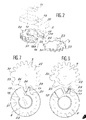
- the reference 1 designates the trunk, shown open, of a cylinder lock according to the invention. This comprises, very schematically illustrated in the drawing, a sliding rod 2 whose displacement allows transverse actuation projecting or recessed in the trunk 1 of locking elements (not shown), the lock being itself mounted in the thickness of the frame or leaf of a door or the like.
- the sliding rod 2 is itself actuated by a rack nut 3, the movement of which is obtained by meshing it with a pinion 4, fixed on an axis 5 perpendicular to the plane of Figure 1.
- Rotation in one direction or in the other of the drive pinion 4 is produced by means of a set of two other control pinions, respectively a first pinion 6 and a second pinion 7, meshing with each other.
- the first pinion 6 is mounted in a circular recess of a support 8, extended at its lower part by an elongated housing 9.
- This pinion 6 furthermore has a hollowed-out central part 10, allowing the axial engagement in this pinion of a barrel body 11, the lower part 12 of which enters the housing 9, thus being guided by the latter.
- the support 8 of the pinion 6 is immobilized in the trunk 1 of the lock and has for this purpose a transverse passage 13 for mounting a locking screw 14 which also passes through the lower part 12 of the barrel.
- the disassembly of the screw 14 thus allows, on request, to change the barrel body 11 to replace it with another in the event of a defect or more generally to replace the initial barrel with another of the same profile but suitable for a different key, especially when the user has lost the first one.
- the body of the barrel 11 comprises a bit 15, mounted movably around the axis of the body under the effect of a key 16 engaged in the latter.
- the profile of the key, as well as the arrangement of the interior parts of the barrel, in particular the pins thereof, authorizing rotation of the bit 15 only for a determined and precise profile of this key once introduced into the body 11, are not described here, these arrangements being in themselves conventional and well known in the art.
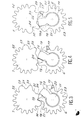
- the first pinion 6 has two actuating teeth, respectively 17 and 18, forming extra thicknesses on top of the pinion and separated from each other by a slot 19 into which the bit 15 of the barrel is inserted with play when that -This is mounted in the recessed central part 10 of the pinion.
- the teeth 17 and 18 are thus arranged on either side of the bit 15 which, in a way, plays the role, in the pinion 6, of a large complementary tooth, in fact missing in the space 19.
- teeth 17 and 18 have, opposite the slot 19, housings 17a and 18a respectively, closed on the side of this slot but open towards the outside.
- the pinion 6 also comprises, beyond the housings 17a and 18a, two notches 20 and 21 respectively, the profile of which is determined in a manner which will be specified below. Beyond these notches, the pinion finally comprises a series of teeth 22 for driving homologous teeth 23 of the second pinion 7.
- the teeth 22 and 23 having an appropriate profile but a maximum width very much less than that of the teeth d actuation 17 and 18 on the one hand and notches 20 and 21 on the other.
- the second pinion 7 is mounted on the axis 5 carrying the pinion 4 so that, from the movement which it receives from the first pinion 6, it in turn transmits a corresponding rotation to the pinion 4 and by the latter, to the follower 3.
- the actuation teeth 17 and 18 of the first pinion 6 are in a symmetrical position relative to the housing 9 in which the lower part 12 of the barrel body 11 engages. , the bit 15 also being inside this housing.
- the second pinion 7 is arranged so that it has respectively, opposite the elements constituting the first pinion, housings, homologous parts, but nevertheless not identical, arranged to cooperate with the first during the mutual rotation in opposite directions of the two pinions.
- the pinion 7 thus comprises, firstly two receiving teeth 24 and 25, suitable for successively and respectively engaging in the housings 17a and 18a of the first pinion.
- receiving teeth 24 and 25 are separated from each other, on the periphery of the pinion 7, by a free space 26 whose profile and in particular the width are substantially identical to those of the slot 19 of the first pinion 6.
- the pinion 7 comprises, beyond the hollow parts 27 and 28, two complementary extensions 29 and 30, these having a rounded profile with convex and continuous curvature, corresponding to the hollows of the notches 20 and 21 of the first pinion 6.
- the receiving teeth 24 and 25 on the one hand, the complementary extensions 29 and 30 on the other hand of the second pinion 7, are produced in the plane of the latter, as illustrated in the perspective view of Figure 2, the pinion 4 can therefore be mounted on top of this pinion 7, so that the thickness of the assembly is actually only the addition of the relative thicknesses of these pinions 4 and 7 and does not exceed not that of the pinion 6, in particular at the level of the actuating teeth 17 and 18 thereof.
- the first pinion 6 has a right to the latter an approximately double thickness and in total practically equal to that of the pinions 4 and 7 thus superimposed.
- the key 16 In the initial position shown in Figure 1, the key 16 is inserted into the barrel 11 and then drives the bit 15 thereof in the direction, for example, counterclockwise.
- the bit 15 thus comes into contact with the lateral blank of the actuating tooth 17 and rotates the first pinion 6 on itself.
- the latter by its teeth 22, meshes with the teeth 23 of the second pinion 7 and thus transmits the movement of the key at the pinion 4 and, from the latter, at the follower 3.
- the difference in width between the slot 19 separating the actuating teeth 17 and 18 of the first pinion and the bit 15, immediately authorizes a slight offset of the second pinion 7 relative to the first 6, such that, in case of force exerted on this second pinion to make it then rotate clockwise, the first pinion 6 is instantly blocked in its rotation by the receiving tooth 25 which can no longer engage in the housing 17a tooth 17 but laterally abuts against the blank thereof.
- the mechanism according to the invention therefore makes it possible, by agreeing to all the advantages of the conventional solution, in particular with regard to the safety of its operation in the event of a force exerted on the sliding rod introducing the unlocking of the lock, to carry out the latter with a significantly reduced thickness, allowing it to be mounted in narrow supports, shielded or not.
Landscapes
- Lock And Its Accessories (AREA)
Applications Claiming Priority (2)
| Application Number | Priority Date | Filing Date | Title |
|---|---|---|---|
| FR8616376 | 1986-11-25 | ||
| FR8616376A FR2607176B1 (fr) | 1986-11-25 | 1986-11-25 | Serrure dont le barillet est accouple, par un jeu de pignons, avec la piece actionnant le pene |
Publications (3)
| Publication Number | Publication Date |
|---|---|
| EP0270425A2 true EP0270425A2 (de) | 1988-06-08 |
| EP0270425A3 EP0270425A3 (en) | 1988-07-06 |
| EP0270425B1 EP0270425B1 (de) | 1990-06-20 |
Family
ID=9341168
Family Applications (1)
| Application Number | Title | Priority Date | Filing Date |
|---|---|---|---|
| EP19870402536 Expired - Lifetime EP0270425B1 (de) | 1986-11-25 | 1987-11-10 | Schloss mit Antriebsritzel zwischen Rotor und Riegel |
Country Status (4)
| Country | Link |
|---|---|
| EP (1) | EP0270425B1 (de) |
| DE (1) | DE3763325D1 (de) |
| ES (1) | ES2016858B3 (de) |
| FR (1) | FR2607176B1 (de) |
Cited By (10)
| Publication number | Priority date | Publication date | Assignee | Title |
|---|---|---|---|---|
| FR2690944A1 (fr) * | 1992-05-05 | 1993-11-12 | Brogser Sa | Serrure à barillet. |
| GB2272247A (en) * | 1992-11-05 | 1994-05-11 | Gary Christian | Axial push and pull locking device |
| GB2274306A (en) * | 1993-01-13 | 1994-07-20 | Parys Remi E Van | Lock mechanism |
| FR2707322A1 (fr) * | 1993-07-05 | 1995-01-13 | Laperche Sa | Serrure à cylindre et à engrenages de transmission du mouvement au pêne de celle-ci. |
| FR2708305A1 (fr) * | 1993-06-30 | 1995-02-03 | Laperche Sa | Serrure à engrenages et à cylindre perfectionnée. |
| WO1998045558A1 (en) * | 1997-04-08 | 1998-10-15 | Lockwood Australia Pty. Ltd. | Lock mechanism |
| EP0906996A2 (de) | 1997-10-03 | 1999-04-07 | C.I.S.A. Costruzioni Italiane Serrature Affini S.p.A. | Schloss mit einem Getriebe für die Betätigung zumindest eines Riegels |
| RU2425203C2 (ru) * | 2006-02-17 | 2011-07-27 | Моттура Серратуре Ди Сикуредза С.П.А. | Замок с предохранителем |
| ITNO20100002A1 (it) * | 2010-05-05 | 2011-11-06 | Mimosa Arso | Serratura di sicurezza per porte basculanti |
| FR3008123A1 (fr) * | 2013-07-02 | 2015-01-09 | Tordjman | Cylindre de serrure, serrure equipee d'un tel cylindre |
Families Citing this family (2)
| Publication number | Priority date | Publication date | Assignee | Title |
|---|---|---|---|---|
| DE9104553U1 (de) * | 1991-04-13 | 1991-06-06 | BKS GmbH, 5620 Velbert | Mehrriegel-Türschloß |
| DE19650136B4 (de) * | 1996-12-03 | 2006-06-29 | Brose Schließsysteme GmbH & Co.KG | Kraftfahrzeug-Türschloß o. dgl. mit Freilauf |
Family Cites Families (1)
| Publication number | Priority date | Publication date | Assignee | Title |
|---|---|---|---|---|
| DE3021086A1 (de) * | 1980-06-04 | 1981-12-10 | Gretsch-Unitas Gmbh Baubeschlagfabrik, 7257 Ditzingen | Antrieb fuer wenigstens ein riegelglied |
-
1986
- 1986-11-25 FR FR8616376A patent/FR2607176B1/fr not_active Expired
-
1987
- 1987-11-10 DE DE8787402536T patent/DE3763325D1/de not_active Expired - Lifetime
- 1987-11-10 ES ES87402536T patent/ES2016858B3/es not_active Expired - Lifetime
- 1987-11-10 EP EP19870402536 patent/EP0270425B1/de not_active Expired - Lifetime
Cited By (19)
| Publication number | Priority date | Publication date | Assignee | Title |
|---|---|---|---|---|
| FR2690944A1 (fr) * | 1992-05-05 | 1993-11-12 | Brogser Sa | Serrure à barillet. |
| GB2272247A (en) * | 1992-11-05 | 1994-05-11 | Gary Christian | Axial push and pull locking device |
| DE4400473C2 (de) * | 1993-01-13 | 2003-11-20 | Parys Remi E Van | Schloßmechanismus und mit einem derartigen Schloßmechanismus versehenes Schloß |
| GB2274306A (en) * | 1993-01-13 | 1994-07-20 | Parys Remi E Van | Lock mechanism |
| FR2704264A1 (fr) * | 1993-01-13 | 1994-10-28 | Parys Remi E Van | Mécanisme de serrure et fermeture munie d'un mécanisme de serrure de ce type. |
| GB2274306B (en) * | 1993-01-13 | 1995-10-11 | Parys Remi E Van | Lock mechanism,and a locking device incorporating such a lock mechanism |
| BE1008364A5 (nl) * | 1993-01-13 | 1996-04-02 | Parys Remi E Van | Slotmechanisme en sluiting voorzien van dergelijk slotmechanisme. |
| FR2708305A1 (fr) * | 1993-06-30 | 1995-02-03 | Laperche Sa | Serrure à engrenages et à cylindre perfectionnée. |
| FR2707322A1 (fr) * | 1993-07-05 | 1995-01-13 | Laperche Sa | Serrure à cylindre et à engrenages de transmission du mouvement au pêne de celle-ci. |
| WO1998045558A1 (en) * | 1997-04-08 | 1998-10-15 | Lockwood Australia Pty. Ltd. | Lock mechanism |
| GB2338264A (en) * | 1997-04-08 | 1999-12-15 | Lockwood Australia Pty Ltd | Lock mechanism |
| AU719921B2 (en) * | 1997-04-08 | 2000-05-18 | Lockwood Security Products Pty Limited | Lock mechanism |
| GB2338264B (en) * | 1997-04-08 | 2001-06-13 | Lockwood Australia Pty Ltd | Lock mechanism |
| US6374650B1 (en) | 1997-04-08 | 2002-04-23 | Lockwood Australia Pty Ltd. | Lock mechanism |
| EP0906996A3 (de) * | 1997-10-03 | 2001-06-13 | CISA S.p.A. | Schloss mit einem Getriebe für die Betätigung zumindest eines Riegels |
| EP0906996A2 (de) | 1997-10-03 | 1999-04-07 | C.I.S.A. Costruzioni Italiane Serrature Affini S.p.A. | Schloss mit einem Getriebe für die Betätigung zumindest eines Riegels |
| RU2425203C2 (ru) * | 2006-02-17 | 2011-07-27 | Моттура Серратуре Ди Сикуредза С.П.А. | Замок с предохранителем |
| ITNO20100002A1 (it) * | 2010-05-05 | 2011-11-06 | Mimosa Arso | Serratura di sicurezza per porte basculanti |
| FR3008123A1 (fr) * | 2013-07-02 | 2015-01-09 | Tordjman | Cylindre de serrure, serrure equipee d'un tel cylindre |
Also Published As
| Publication number | Publication date |
|---|---|
| FR2607176B1 (fr) | 1989-03-31 |
| EP0270425B1 (de) | 1990-06-20 |
| DE3763325D1 (de) | 1990-07-26 |
| ES2016858B3 (es) | 1990-12-01 |
| EP0270425A3 (en) | 1988-07-06 |
| FR2607176A1 (fr) | 1988-05-27 |
Similar Documents
| Publication | Publication Date | Title |
|---|---|---|
| EP0270425B1 (de) | Schloss mit Antriebsritzel zwischen Rotor und Riegel | |
| EP0943768B1 (de) | Rückstellvorrichtung des Betätigungsorgans für ein Schlossgehäuse, Treibstangenschloss oder dergleichen | |
| CH620014A5 (de) | ||
| FR2641312A1 (fr) | Mecanisme pour portes tournantes basculantes | |
| EP0778595B1 (de) | Sicherheitsschalter mit Schlüssel | |
| EP0140740B1 (de) | Sicherheitsschloss | |
| EP0645511A1 (de) | Schloss für eine Kraftfahrzeugtür | |
| EP0801193A1 (de) | Einsteckschloss | |
| EP0764565B1 (de) | Angetriebenes Lenkradschloss für Kraftfahrzeuge | |
| EP0325813B1 (de) | Schloss mit Kupplungs- und Entkupplungsvorrichtung | |
| EP3808925B1 (de) | Schloss für einen öffnungsflügel eines kraftfahrzeugs | |
| EP0170577A1 (de) | Bedienungsvorrichtung zum Öffnen von Kraftfahrzeugtürschlössern | |
| FR2759333A1 (fr) | Mecanisme d'articulation pour siege de vehicule, et siege de vehicule comportant un tel mecanisme | |
| EP0940529A1 (de) | Doppelsicherheitszylinder | |
| EP0230808B1 (de) | Verriegelungsvorrichtung für Kraftfahrzeugtürschloss | |
| EP1681411B1 (de) | Schlosszylinder für Schlüssel mit nicht kreisförmigem Querschnitt | |
| FR2941544A3 (fr) | Dispositif d'actionnement manuel pour deux organes de vehicule automobile devant etre actionnes alternativement | |
| EP0846603B1 (de) | Antrieb, insbesondere für eine elektrische Fahrzeugdiebstahlsicherung | |
| FR2552146A1 (fr) | Serrure de surete | |
| EP4050182B1 (de) | Vorrichtung zur steuerung eines verriegelungs-/entriegelungsmechanismus eines öffnungsflügels | |
| FR2766441A1 (fr) | Antivol electrique comportant des moyens complementaires de blocage du pene | |
| EP0841449A1 (de) | Monodirektionaler Treibstangenverschluss | |
| EP0869236B1 (de) | Von einer Seite aus betätigbarer Sicherheitszylinder selbst wenn ein Schlüssel auf der anderen Seite eingesteckt ist | |
| EP1702125B1 (de) | Einrichtung zur selektiven sperrung der betätigungsbewegung eines sicherheitsschlosses mit zuhaltungen und bewegbarer zahnstange | |
| FR2707322A1 (fr) | Serrure à cylindre et à engrenages de transmission du mouvement au pêne de celle-ci. |
Legal Events
| Date | Code | Title | Description |
|---|---|---|---|
| PUAI | Public reference made under article 153(3) epc to a published international application that has entered the european phase |
Free format text: ORIGINAL CODE: 0009012 |
|
| PUAL | Search report despatched |
Free format text: ORIGINAL CODE: 0009013 |
|
| AK | Designated contracting states |
Kind code of ref document: A2 Designated state(s): BE DE ES GB IT |
|
| AK | Designated contracting states |
Kind code of ref document: A3 Designated state(s): BE DE ES GB IT |
|
| 17P | Request for examination filed |
Effective date: 19881215 |
|
| 17Q | First examination report despatched |
Effective date: 19891123 |
|
| ITF | It: translation for a ep patent filed | ||
| GRAA | (expected) grant |
Free format text: ORIGINAL CODE: 0009210 |
|
| AK | Designated contracting states |
Kind code of ref document: B1 Designated state(s): BE DE ES GB IT |
|
| GBT | Gb: translation of ep patent filed (gb section 77(6)(a)/1977) | ||
| REF | Corresponds to: |
Ref document number: 3763325 Country of ref document: DE Date of ref document: 19900726 |
|
| PLBE | No opposition filed within time limit |
Free format text: ORIGINAL CODE: 0009261 |
|
| STAA | Information on the status of an ep patent application or granted ep patent |
Free format text: STATUS: NO OPPOSITION FILED WITHIN TIME LIMIT |
|
| 26N | No opposition filed | ||
| ITTA | It: last paid annual fee | ||
| PGFP | Annual fee paid to national office [announced via postgrant information from national office to epo] |
Ref country code: GB Payment date: 19971110 Year of fee payment: 11 |
|
| PGFP | Annual fee paid to national office [announced via postgrant information from national office to epo] |
Ref country code: ES Payment date: 19971128 Year of fee payment: 11 |
|
| PG25 | Lapsed in a contracting state [announced via postgrant information from national office to epo] |
Ref country code: GB Free format text: LAPSE BECAUSE OF NON-PAYMENT OF DUE FEES Effective date: 19981110 |
|
| PG25 | Lapsed in a contracting state [announced via postgrant information from national office to epo] |
Ref country code: ES Free format text: LAPSE BECAUSE OF EXPIRATION OF PROTECTION Effective date: 19981111 |
|
| GBPC | Gb: european patent ceased through non-payment of renewal fee |
Effective date: 19981110 |
|
| REG | Reference to a national code |
Ref country code: ES Ref legal event code: FD2A Effective date: 20010201 |
|
| PG25 | Lapsed in a contracting state [announced via postgrant information from national office to epo] |
Ref country code: IT Free format text: LAPSE BECAUSE OF NON-PAYMENT OF DUE FEES Effective date: 20051110 |
|
| PGFP | Annual fee paid to national office [announced via postgrant information from national office to epo] |
Ref country code: DE Payment date: 20061019 Year of fee payment: 20 |
|
| PGFP | Annual fee paid to national office [announced via postgrant information from national office to epo] |
Ref country code: BE Payment date: 20061030 Year of fee payment: 20 |
|
| BE20 | Be: patent expired |
Owner name: *STREMLER Effective date: 20071110 |