EP0841449A1 - Monodirektionaler Treibstangenverschluss - Google Patents
Monodirektionaler Treibstangenverschluss Download PDFInfo
- Publication number
- EP0841449A1 EP0841449A1 EP97402560A EP97402560A EP0841449A1 EP 0841449 A1 EP0841449 A1 EP 0841449A1 EP 97402560 A EP97402560 A EP 97402560A EP 97402560 A EP97402560 A EP 97402560A EP 0841449 A1 EP0841449 A1 EP 0841449A1
- Authority
- EP
- European Patent Office
- Prior art keywords
- follower
- housing
- rack
- rotation
- easel
- Prior art date
- Legal status (The legal status is an assumption and is not a legal conclusion. Google has not performed a legal analysis and makes no representation as to the accuracy of the status listed.)
- Granted
Links
Images

Classifications
-
- E—FIXED CONSTRUCTIONS
- E05—LOCKS; KEYS; WINDOW OR DOOR FITTINGS; SAFES
- E05C—BOLTS OR FASTENING DEVICES FOR WINGS, SPECIALLY FOR DOORS OR WINDOWS
- E05C9/00—Arrangements of simultaneously actuated bolts or other securing devices at well-separated positions on the same wing
- E05C9/02—Arrangements of simultaneously actuated bolts or other securing devices at well-separated positions on the same wing with one sliding bar for fastening when moved in one direction and unfastening when moved in opposite direction; with two sliding bars moved in the same direction when fastening or unfastening
- E05C9/021—Arrangements of simultaneously actuated bolts or other securing devices at well-separated positions on the same wing with one sliding bar for fastening when moved in one direction and unfastening when moved in opposite direction; with two sliding bars moved in the same direction when fastening or unfastening with rack and pinion mechanism
-
- E—FIXED CONSTRUCTIONS
- E05—LOCKS; KEYS; WINDOW OR DOOR FITTINGS; SAFES
- E05B—LOCKS; ACCESSORIES THEREFOR; HANDCUFFS
- E05B15/00—Other details of locks; Parts for engagement by bolts of fastening devices
- E05B15/0053—Other details of locks; Parts for engagement by bolts of fastening devices means providing a stable, i.e. indexed, position of lock parts
Definitions
- the present invention relates to a fitting for opening with a unidirectional lever.
- cremone bolts comprise, in a known manner, a cremone bolt housing housing the mechanism for moving the rods.
- the cremone bolt and the rods are fixed in the grooves of the uprights and / or crosspieces depending on the type of opening of the opening.
- the housing comprises a nut controlled in rotation over an angle of 90 ° by a handle for example, and an easel supporting two lugs fixed respectively to two rods of the cremone bolt.
- This easel generally comprises a rack cooperating with teeth arranged on a circular peripheral portion of the follower.
- the cremone bolt housing must be housed in the groove made in the opening, the width and the thickness of this housing must remain respectively less than the depth of the groove in the plane of the opening and the width this groove in the plan of the sash of the opening.
- the faces of the housing, supporting the follower adjacent to the rack of the bridge, therefore have a width, in a transverse direction of the housing, limited.
- the bridge extending parallel and adjacent to a side wall of the housing, generally has a thickness sufficient to withstand the mechanical forces generated by the follower meshing in its rack.
- the follower housed between this bridge and the other side wall of the housing, generally has a diameter between half and two thirds of the width of the housing.
- Patent application EP 0 167 386 describes a locking device in which the follower has a diameter corresponding to three-quarters of the width of the housing.
- This small dimension of the follower has the effect of creating a relatively small stroke of the bridge.
- This race is transmitted or resumed by the rods of the cremone bolt which has locking elements.
- the latter which may be of the roller type, penetrate keepers capable of accommodating these elements on the displacement travel of the rod.
- the strikes have an opening which allows the passage of the locking element, then a ramp secured to a wall on which the locking element rolls or slides. The latter is ensured when the roller is properly engaged at the rear of this wall.
- the purpose of the present invention is to solve the aforementioned drawbacks and to propose a one-way cremone bolt fitting which can be applied to all types of existing opening.
- the fitting for an opening leaf contemplated by the invention comprises a monodirectional cremone bolt and a cremone bolt housing adapted to be housed in a groove in the opening leaf, this casing comprising a nut controlled in rotation at a 90 ° angle by a handle, an easel supporting two lugs fixed respectively to two rods of the cremone bolt and comprising a rack cooperating with teeth arranged on a circular peripheral portion of the follower on an arc of a 90 ° circle.
- the largest diameter of the follower is substantially equal to the width of the housing, and the housing comprises a lumen in a longitudinal side wall, a second circular peripheral portion of the follower having a radius substantially equal to the distance separating the axis of the follower of this side wall of the housing and adapted to circulate in rotation in said lumen.
- the locking bolt caster thus makes maximum use of the width possibilities of this casing, that is to say the transverse dimension of the casing taken in the plane of the opening when the casing is in place in the groove.
- the largest diameter of the follower is understood to mean the greatest distance separating two peripheral points of the follower aligned with the center of rotation of the latter.
- the arrangement of the teeth on a 90 ° arc allows the follower to remain engaged with the rack over the entire rotation of the follower actuated by the handle.
- the light of the housing makes it possible to overcome the internal dimensions of the housing to further increase the diameter of the follower and consolidate the latter so that it can withstand the mechanical forces exerted on it during its rotation.
- the bridge has a substantially U shape in a plane parallel to an outer face of the housing, the branches of the bridge supporting the pins and the base of the bridge supporting the rack, the follower being housed between the branches of the easel.
- the rod drive axis must imperatively correspond to the center of the profile groove, by configuring the U-shaped bridge, we can offset the axis of the follower and therefore offset it from the axis of drive of the rod, which allows respecting the reversibility of the cremone bolt case.
- the asymmetrical arrangement of the center of the follower allows reversibility which, depending on the case, brings the center of the follower closer or farther away from the edge of the opening. In the remote position, the use of a handle with rosette is possible. Conversely, bringing the axis of the follower closer to the edge of the sash allows the fitting of a handle without rosette, with a thin barrel.
- the base of the bridge extends substantially parallel to a side wall of the housing, the base of the bridge having an offset portion, supporting the rack and extending in a groove formed on an internal face of the wall. lateral of the housing, this groove having a length in the longitudinal direction of the housing at least equal to the stroke of the bridge.
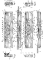
- the fitting for opening leaf according to the invention comprises a cremone bolt housing 1, the external face 2 of which is illustrated in FIG. 1.
- This fitting is in particular intended for opening of the tilting type, requiring fittings with so-called perimeter cremones.
- the outer face 2 comprises a central opening 3, arranged in a median transverse plane of the housing 1 and adapted to receive a follower housed in the housing as will be described below; the follower receives in its center an operating square 4, crossing or not, connecting a handle (not shown) to the mechanism.
- the square can be secured to the follower or preferably removable to allow the adaptation of any type of handle.
- the outer face 2 of the housing also has two circular openings 5, aligned with the central opening 3, for fixing, by means of screws for example, the housing in the bottom of the groove of the profile of the opening.
- the other outer face 2 ′ of the housing (see FIG. 8) is arranged parallel to this first face 2 and also includes openings opposite the openings 3, 5 and 6 previously described.
- the outer face 2 further comprises two longitudinal slots 7, extending in the longitudinal direction XX of the housing 1 and adapted respectively for the passage of a lug 8 engaged with a rod 9 as illustrated in FIG. 2 and secured to a easel described below.
- the pins 8 are moved in translation in the longitudinal slots 7 by a mechanism, described below, housed in the housing 1.
- the length of the longitudinal slots 7 therefore corresponds substantially to the travel of the lugs 8.
- This groove bottom 10 comprises openings 11, 12, 13 opposite the openings 3, 5 and 6 of the outer face 2 of the housing, to allow respectively the passage of the square 4 of the follower and the means for fixing the housing 1 and the handle.
- FIG. 5 illustrates the cremone mechanism housed in the housing 1.
- the housing 1 comprises a follower 14 controlled in rotation at an angle of 90 ° C by means of a square 4 mounted in a handle or crutch.
- a bridge 15 supports the two lugs 8 and comprises a rack 16 cooperating with teeth 17 arranged on a circular peripheral portion 14a of the follower 14.
- the latter has a second circular peripheral portion 14b which extends substantially over a 270 ° axis of a circle.
- the first circular peripheral portion 14a has teeth on a complementary arc of 90 ° C.
- the follower 14 thus has two circular peripheral portions 14a and 14b, centered on the axis of rotation Y-Y of the follower, the radius of the first peripheral portion 14a being greater than the radius of the second peripheral portion 14b.
- the follower 14 is arranged in the housing so that the radius of the second circular peripheral portion 14b is substantially equal to the distance separating the axis of the follower YY from a longitudinal side wall 1a of the housing 1, this side wall comprising it lumen 18 in which the second circular peripheral portion 14b of the follower 14 can circulate in rotation.
- this side wall will be called the faceplate wall 1a of the housing and the other longitudinal side wall will be called the bottom wall 1b of the housing 1.
- the largest diameter of the follower 14, that is to say, in the embodiment shown, the sum of the radius of the first circular peripheral portion 14a equipped with teeth 17 and the second circular peripheral portion 14b, is substantially equal to the width of the housing 1, that is to say the distance separating the internal faces of the faceplate and bottom walls 1a, 1b of the housing 1.
- the dimensions of the follower 14 thus result from a compromise between a toothed peripheral portion 14a of a radius large enough to develop a large stroke of the bridge 15 driven by the rack 16 and a smooth peripheral portion 14b of a sufficiently large radius to consolidate the follower 14 and withstand the mechanical forces exerted on it during its rotation and its gear in the rack 16.
- the distance separating the center of the follower 14 from the edge of the opening section must be sufficient to prevent the body of the handle from overflowing beyond the opening section.
- the first circular peripheral portion 14a has teeth on a quarter of a circle, so as to be operational over the entire rotational movement of the follower 14, end teeth 17 ', delimiting this circular peripheral portion 14a, extending respectively along two perpendicular axes, intersecting at the center of the follower 14.
- the bridge 15 has a substantially U shape in a plane parallel to an outer face 2 of the housing 1, the branches of the bridge supporting the lugs 8 and the base of the bridge supporting the rack 16, the nut 14 being housed between the branches of the bridge 15.
- the asymmetrical arrangement of the center of the follower allows reversibility which, depending on the case, brings the center of the follower closer or further away from the edge of the profile.
- the use of the handle with rosette is possible.
- a reconciliation can allow the installation of a handle without rosette, with a thin barrel.
- the asymmetry allows the housing to lend itself to various assemblies depending on the position of the groove in the profile.
- right or left reversibility is acquired when the follower can accommodate a square on one and / or the other of its faces or if the center of the follower is located halfway up the housing. In the latter case, it suffices to pivot the handle and the 180 ° square to obtain the application opening on the left or on the right.
- the base of the easel 15 extends parallel to the second side wall 1b of the housing 1, called the bottom wall, and comprises an offset portion 19 supporting the rack 16.
- This offset portion 19 extends in a groove 20 formed on an internal face of the bottom wall 1b of the housing 1.
- the groove 20 has a length, the longitudinal direction X-X of the housing 1 at least equal to the stroke of the bridge 15 and is adapted to accommodate this bridge 15 over the entire length of its stroke.
- the base of the bridge 15 has an L-shaped cross section, the base of the L being perpendicular to the outer face 2 of the housing 1 and supporting the rack 16.
- the branch of the L extends in a plane parallel to the outer face 2 of the housing, the follower 14 being housed between this outer face 2 and the branch of the L of the bridge 15.
- the length of the housing 1 is between 33 and 36 mm and preferably equal to 35.5 mm.
- the radius of the first toothed peripheral portion 14a is substantially equal to 17.8 mm, thus allowing a travel of 28 mm, compared to around 17 mm in conventional fittings.
- the radius of the second circular peripheral portion 14b of the follower is between 15 and 17 mm.
- the carpenter can get rid of the exact positioning of the strikes on the frame and the consequences due to the deformation of an opening during use.
- the housing further comprises an elastic blade 21 fixed at its ends to a face of the housing 1, such as the external face 2 by means of fixing studs 22.
- the follower 14 comprises two finger elements 23, arranged at 90 ° in an arc centered on the axis of rotation YY of the follower 14 and the elastic blade 21 comprises, substantially in its middle, a notch 24, of shape complementary to the finger elements 23.
- the distance separating this notch 24 from the center of rotation of the follower 14 is substantially less than the distance separating the finger elements 23 from the center of rotation of the follower 14.
- finger-forming elements 23 are thus housed in the notch 24 at the end of the rotary rotation of the follower, at an angle of 90 ° C, in a direct or indirect direction around its axis of rotation YY, corresponding to the extreme positions of locking and unlocking of the lever.
- the finger elements 23 thus put the elastic blade 21 in tension, against the elastic restoring force of the blade tending to bring this blade 21 in a direction coincident with the straight line passing through its ends fixed to the housing 1.
- the elastic stress is felt by the user through the handle, so that the unlocking / locking indexation, i.e. the end of travel of the rods 9 and the bridge 15 becomes clearly noticeable.
- This elastic blade 21 thus makes it possible to index the movement of the mechanism, directly at the level of the follower 14, by overcoming the mechanical play inevitably existing between the different moving parts of the mechanism.
- the elastic blade 21 extends in a direction substantially parallel to the direction of translation XX of the rack 16 of the bridge 15, the notch 24 of the elastic blade 21 being aligned with the center of rotation of the follower 14 and the gear point of the teeth 17 of the follower 14 in the rack 16.
- the follower 14 comprises a concentric ring 25, extending in a plane parallel to the plane containing the first and second peripheral portions 14a, 14b, the finger elements 23 extending from this ring 25, each being aligned with an axis passing through the center of rotation of the follower 14 and an end tooth 17 ′ of the first circular peripheral portion 14a.
- the follower 14 is made integral with the outer and inner faces of the housing 1 by means of circular lights 26, 27 as illustrated in FIG. 11 in which the faces 28, 29 of the follower 14 are inscribed, formed of two pads 28, 29 substantially cylindrical, centered on the axis of rotation YY of the follower 14.
- the end of the movement is indexed by the insertion of a finger element 23 into the notch 24 of the elastic blade 21.
Landscapes
- Engineering & Computer Science (AREA)
- Mechanical Engineering (AREA)
- Pivots And Pivotal Connections (AREA)
- Vehicle Body Suspensions (AREA)
- Control Of Throttle Valves Provided In The Intake System Or In The Exhaust System (AREA)
- Devices For Conveying Motion By Means Of Endless Flexible Members (AREA)
- Transition And Organic Metals Composition Catalysts For Addition Polymerization (AREA)
- Casings For Electric Apparatus (AREA)
- Structures Of Non-Positive Displacement Pumps (AREA)
- Error Detection And Correction (AREA)
- Securing Of Glass Panes Or The Like (AREA)
- Detection And Prevention Of Errors In Transmission (AREA)
- Details Of Aerials (AREA)
- Window Of Vehicle (AREA)
- Gripping On Spindles (AREA)
- Power-Operated Mechanisms For Wings (AREA)
- Diaphragms For Electromechanical Transducers (AREA)
- Electrotherapy Devices (AREA)
- Lock And Its Accessories (AREA)
Applications Claiming Priority (2)
| Application Number | Priority Date | Filing Date | Title |
|---|---|---|---|
| FR9613598 | 1996-11-07 | ||
| FR9613598A FR2755461B1 (fr) | 1996-11-07 | 1996-11-07 | Cremone monodirectionnelle |
Publications (2)
| Publication Number | Publication Date |
|---|---|
| EP0841449A1 true EP0841449A1 (de) | 1998-05-13 |
| EP0841449B1 EP0841449B1 (de) | 2002-01-23 |
Family
ID=9497425
Family Applications (1)
| Application Number | Title | Priority Date | Filing Date |
|---|---|---|---|
| EP97402560A Expired - Lifetime EP0841449B1 (de) | 1996-11-07 | 1997-10-28 | Monodirektionaler Treibstangenverschluss |
Country Status (10)
| Country | Link |
|---|---|
| EP (1) | EP0841449B1 (de) |
| JP (1) | JPH10292707A (de) |
| CN (1) | CN1198501A (de) |
| AT (1) | ATE212410T1 (de) |
| DE (1) | DE69710027T2 (de) |
| DK (1) | DK0841449T3 (de) |
| ES (1) | ES2170929T3 (de) |
| FR (1) | FR2755461B1 (de) |
| PT (1) | PT841449E (de) |
| TW (1) | TW342422B (de) |
Cited By (4)
| Publication number | Priority date | Publication date | Assignee | Title |
|---|---|---|---|---|
| EP1452676A1 (de) * | 2003-02-25 | 2004-09-01 | Roto Frank Ag | Getriebe für ein Fenster oder dergleichen mit integrierter Rastung, insbesondere Spreizgetriebe |
| EP1650380A1 (de) * | 2004-10-22 | 2006-04-26 | GSG INTERNATIONAL S.p.A. | Griff für Türe und Fenster |
| CN100422499C (zh) * | 2005-07-15 | 2008-10-01 | Gsg国际股份有限公司 | 用于门或窗的操作单元 |
| IT201900013482A1 (it) * | 2019-07-31 | 2021-01-31 | Masterlab S R L Unipersonale | Dispositivo di movimentazione di organi di manovra o di chiusura di un serramento. |
Citations (5)
| Publication number | Priority date | Publication date | Assignee | Title |
|---|---|---|---|---|
| FR2393132A1 (fr) * | 1977-05-12 | 1978-12-29 | Ferco Int Usine Ferrures | Cremone notamment cremone a tetiere pour fenetres, portes et analogues |
| EP0167386A2 (de) * | 1984-07-05 | 1986-01-08 | Thomas John Wood | Sicherheitsvorrichtung für Drehfenster o.dgl. |
| GB2234777A (en) * | 1989-08-09 | 1991-02-13 | Regent Lock Co Ltd | Operating mechanism for locking device |
| DE4409420A1 (de) * | 1993-03-23 | 1994-09-29 | Giesse Spa | Betätigungsvorrichtung für Handhaben von Türen und Fenstern |
| DE29613802U1 (de) * | 1996-08-09 | 1996-09-26 | Siegenia-Frank Kg, 57074 Siegen | Einsteckgetriebe für die Betätigung von Treibstangenbeschlägen an Fenstern, Türen o.dgl. |
-
1996
- 1996-11-07 FR FR9613598A patent/FR2755461B1/fr not_active Expired - Fee Related
-
1997
- 1997-10-28 DE DE69710027T patent/DE69710027T2/de not_active Expired - Fee Related
- 1997-10-28 ES ES97402560T patent/ES2170929T3/es not_active Expired - Lifetime
- 1997-10-28 AT AT97402560T patent/ATE212410T1/de not_active IP Right Cessation
- 1997-10-28 DK DK97402560T patent/DK0841449T3/da active
- 1997-10-28 EP EP97402560A patent/EP0841449B1/de not_active Expired - Lifetime
- 1997-10-28 PT PT97402560T patent/PT841449E/pt unknown
- 1997-11-06 CN CN97125979.8A patent/CN1198501A/zh active Pending
- 1997-11-06 JP JP9319195A patent/JPH10292707A/ja active Pending
- 1997-11-06 TW TW086116539A patent/TW342422B/zh active
Patent Citations (5)
| Publication number | Priority date | Publication date | Assignee | Title |
|---|---|---|---|---|
| FR2393132A1 (fr) * | 1977-05-12 | 1978-12-29 | Ferco Int Usine Ferrures | Cremone notamment cremone a tetiere pour fenetres, portes et analogues |
| EP0167386A2 (de) * | 1984-07-05 | 1986-01-08 | Thomas John Wood | Sicherheitsvorrichtung für Drehfenster o.dgl. |
| GB2234777A (en) * | 1989-08-09 | 1991-02-13 | Regent Lock Co Ltd | Operating mechanism for locking device |
| DE4409420A1 (de) * | 1993-03-23 | 1994-09-29 | Giesse Spa | Betätigungsvorrichtung für Handhaben von Türen und Fenstern |
| DE29613802U1 (de) * | 1996-08-09 | 1996-09-26 | Siegenia-Frank Kg, 57074 Siegen | Einsteckgetriebe für die Betätigung von Treibstangenbeschlägen an Fenstern, Türen o.dgl. |
Cited By (5)
| Publication number | Priority date | Publication date | Assignee | Title |
|---|---|---|---|---|
| EP1452676A1 (de) * | 2003-02-25 | 2004-09-01 | Roto Frank Ag | Getriebe für ein Fenster oder dergleichen mit integrierter Rastung, insbesondere Spreizgetriebe |
| EP1650380A1 (de) * | 2004-10-22 | 2006-04-26 | GSG INTERNATIONAL S.p.A. | Griff für Türe und Fenster |
| CN1763340B (zh) * | 2004-10-22 | 2010-05-05 | Gsg国际股份有限公司 | 门窗把手 |
| CN100422499C (zh) * | 2005-07-15 | 2008-10-01 | Gsg国际股份有限公司 | 用于门或窗的操作单元 |
| IT201900013482A1 (it) * | 2019-07-31 | 2021-01-31 | Masterlab S R L Unipersonale | Dispositivo di movimentazione di organi di manovra o di chiusura di un serramento. |
Also Published As
| Publication number | Publication date |
|---|---|
| FR2755461B1 (fr) | 1998-12-18 |
| FR2755461A1 (fr) | 1998-05-07 |
| DK0841449T3 (da) | 2002-03-25 |
| DE69710027D1 (de) | 2002-03-14 |
| DE69710027T2 (de) | 2002-08-01 |
| CN1198501A (zh) | 1998-11-11 |
| ATE212410T1 (de) | 2002-02-15 |
| ES2170929T3 (es) | 2002-08-16 |
| EP0841449B1 (de) | 2002-01-23 |
| JPH10292707A (ja) | 1998-11-04 |
| TW342422B (en) | 1998-10-11 |
| PT841449E (pt) | 2002-07-31 |
Similar Documents
| Publication | Publication Date | Title |
|---|---|---|
| EP1945889B1 (de) | Mechanismus zur installation eines bediendrehgriffs für ein türschloss und werkzeug zu seinem ausbau | |
| EP0943768B1 (de) | Rückstellvorrichtung des Betätigungsorgans für ein Schlossgehäuse, Treibstangenschloss oder dergleichen | |
| EP2112302A1 (de) | Triebstangenverschluss für Türen | |
| EP0207869A1 (de) | Einlassespagnolette mit zwei Treibstangen und Zentralriegel | |
| EP0841449B1 (de) | Monodirektionaler Treibstangenverschluss | |
| EP0124460A1 (de) | Einbautreibstangenbeschlag für Fenster, Türen oder dergleichen | |
| FR2821381A1 (fr) | Serrure a pene multiples, en particulier pour porte d'entree, porte-fenetre et similaire | |
| EP1291479A1 (de) | Schloss mit Universalaufstellung | |
| FR2794787A1 (fr) | Dispositif de renvoi de fouillot | |
| EP0894921B1 (de) | Schliessvorrichtung, insbesondere Einsteckschloss mit einer Falle, für eine Fenstertür oder dergleichen | |
| CH629106A5 (fr) | Fixation de securite pour ski. | |
| EP0691448A1 (de) | Türscharnier mit Haltevertiefungen, insbesondere in einem Kraftfahrzeug | |
| EP2586940B1 (de) | Verriegelungsvorrichtung eines Öffnungsflügels | |
| FR2715690A1 (fr) | Agencement de support pivotant d'un ouvrant à une partie fixe formant dormant. | |
| EP0894928B1 (de) | Verriegelungsvorrichtung, insbesondere Einsteckschloss für den Flügel einer Tür oder eines Fensters | |
| CH691132A5 (fr) | Dispositif de trasmission pour la manoeuvre d'un store. | |
| FR2583452A1 (fr) | Boitier de cremone a plaquer avec condamnation. | |
| FR2821380A1 (fr) | Serrure de porte a pene demi-tour | |
| EP2061944B1 (de) | Scharnierbaugruppe zur koplanaren fixierung | |
| FR2666369A1 (fr) | Ferrure pour une fenetre, une porte, ou similaire. | |
| EP0308354A1 (de) | Schloss oder Treibstangenbeschlag mit einer Falle | |
| EP0940529A1 (de) | Doppelsicherheitszylinder | |
| EP0769597A1 (de) | Schloss vom Typ eines entkuppelbaren Rotors | |
| FR2908807A1 (fr) | Mecanisme de commande d'une tringle de cremone pour le verrouillage d'un ouvrant de porte en position fermee | |
| FR2505391A1 (fr) | Serrure de haute securite |
Legal Events
| Date | Code | Title | Description |
|---|---|---|---|
| PUAI | Public reference made under article 153(3) epc to a published international application that has entered the european phase |
Free format text: ORIGINAL CODE: 0009012 |
|
| AK | Designated contracting states |
Kind code of ref document: A1 Designated state(s): AT BE CH DE DK ES FI GB GR IT LI NL PT SE |
|
| AX | Request for extension of the european patent |
Free format text: AL;LT;LV;RO;SI |
|
| 17P | Request for examination filed |
Effective date: 19980626 |
|
| AKX | Designation fees paid |
Free format text: AT BE CH DE DK ES FI GB GR IT LI NL PT SE |
|
| RBV | Designated contracting states (corrected) |
Designated state(s): AT BE CH DE DK ES FI GB GR IT LI NL PT SE |
|
| 17Q | First examination report despatched |
Effective date: 20000207 |
|
| GRAG | Despatch of communication of intention to grant |
Free format text: ORIGINAL CODE: EPIDOS AGRA |
|
| GRAG | Despatch of communication of intention to grant |
Free format text: ORIGINAL CODE: EPIDOS AGRA |
|
| GRAH | Despatch of communication of intention to grant a patent |
Free format text: ORIGINAL CODE: EPIDOS IGRA |
|
| GRAH | Despatch of communication of intention to grant a patent |
Free format text: ORIGINAL CODE: EPIDOS IGRA |
|
| GRAA | (expected) grant |
Free format text: ORIGINAL CODE: 0009210 |
|
| REG | Reference to a national code |
Ref country code: GB Ref legal event code: IF02 |
|
| AK | Designated contracting states |
Kind code of ref document: B1 Designated state(s): AT BE CH DE DK ES FI GB GR IT LI NL PT SE |
|
| PG25 | Lapsed in a contracting state [announced via postgrant information from national office to epo] |
Ref country code: NL Free format text: LAPSE BECAUSE OF FAILURE TO SUBMIT A TRANSLATION OF THE DESCRIPTION OR TO PAY THE FEE WITHIN THE PRESCRIBED TIME-LIMIT Effective date: 20020123 Ref country code: FI Free format text: LAPSE BECAUSE OF FAILURE TO SUBMIT A TRANSLATION OF THE DESCRIPTION OR TO PAY THE FEE WITHIN THE PRESCRIBED TIME-LIMIT Effective date: 20020123 |
|
| REF | Corresponds to: |
Ref document number: 212410 Country of ref document: AT Date of ref document: 20020215 Kind code of ref document: T |
|
| REG | Reference to a national code |
Ref country code: CH Ref legal event code: NV Representative=s name: NOVAPAT INTERNATIONAL S.A. Ref country code: CH Ref legal event code: EP |
|
| REF | Corresponds to: |
Ref document number: 69710027 Country of ref document: DE Date of ref document: 20020314 |
|
| REG | Reference to a national code |
Ref country code: DK Ref legal event code: T3 |
|
| GBT | Gb: translation of ep patent filed (gb section 77(6)(a)/1977) |
Effective date: 20020313 |
|
| PG25 | Lapsed in a contracting state [announced via postgrant information from national office to epo] |
Ref country code: SE Free format text: LAPSE BECAUSE OF FAILURE TO SUBMIT A TRANSLATION OF THE DESCRIPTION OR TO PAY THE FEE WITHIN THE PRESCRIBED TIME-LIMIT Effective date: 20020423 |
|
| NLV1 | Nl: lapsed or annulled due to failure to fulfill the requirements of art. 29p and 29m of the patents act | ||
| REG | Reference to a national code |
Ref country code: PT Ref legal event code: SC4A Free format text: AVAILABILITY OF NATIONAL TRANSLATION Effective date: 20020408 |
|
| REG | Reference to a national code |
Ref country code: ES Ref legal event code: FG2A Ref document number: 2170929 Country of ref document: ES Kind code of ref document: T3 |
|
| REG | Reference to a national code |
Ref country code: GR Ref legal event code: EP Ref document number: 20020401166 Country of ref document: GR |
|
| PG25 | Lapsed in a contracting state [announced via postgrant information from national office to epo] |
Ref country code: LI Free format text: LAPSE BECAUSE OF NON-PAYMENT OF DUE FEES Effective date: 20021031 Ref country code: DK Free format text: LAPSE BECAUSE OF NON-PAYMENT OF DUE FEES Effective date: 20021031 Ref country code: CH Free format text: LAPSE BECAUSE OF NON-PAYMENT OF DUE FEES Effective date: 20021031 Ref country code: BE Free format text: LAPSE BECAUSE OF NON-PAYMENT OF DUE FEES Effective date: 20021031 |
|
| PLBE | No opposition filed within time limit |
Free format text: ORIGINAL CODE: 0009261 |
|
| STAA | Information on the status of an ep patent application or granted ep patent |
Free format text: STATUS: NO OPPOSITION FILED WITHIN TIME LIMIT |
|
| 26N | No opposition filed | ||
| BERE | Be: lapsed |
Owner name: *FERCO INTERNATIONAL FERRURES ET SERRURES DE BATIM Effective date: 20021031 |
|
| REG | Reference to a national code |
Ref country code: CH Ref legal event code: PL |
|
| REG | Reference to a national code |
Ref country code: DK Ref legal event code: EBP |
|
| PGFP | Annual fee paid to national office [announced via postgrant information from national office to epo] |
Ref country code: AT Payment date: 20031013 Year of fee payment: 7 |
|
| PGFP | Annual fee paid to national office [announced via postgrant information from national office to epo] |
Ref country code: GR Payment date: 20041027 Year of fee payment: 8 |
|
| PG25 | Lapsed in a contracting state [announced via postgrant information from national office to epo] |
Ref country code: AT Free format text: LAPSE BECAUSE OF NON-PAYMENT OF DUE FEES Effective date: 20041028 |
|
| PGFP | Annual fee paid to national office [announced via postgrant information from national office to epo] |
Ref country code: PT Payment date: 20041028 Year of fee payment: 8 |
|
| PGFP | Annual fee paid to national office [announced via postgrant information from national office to epo] |
Ref country code: ES Payment date: 20041116 Year of fee payment: 8 |
|
| PGFP | Annual fee paid to national office [announced via postgrant information from national office to epo] |
Ref country code: GB Payment date: 20051026 Year of fee payment: 9 |
|
| PG25 | Lapsed in a contracting state [announced via postgrant information from national office to epo] |
Ref country code: IT Free format text: LAPSE BECAUSE OF NON-PAYMENT OF DUE FEES Effective date: 20051028 |
|
| PG25 | Lapsed in a contracting state [announced via postgrant information from national office to epo] |
Ref country code: ES Free format text: LAPSE BECAUSE OF NON-PAYMENT OF DUE FEES Effective date: 20051029 |
|
| PG25 | Lapsed in a contracting state [announced via postgrant information from national office to epo] |
Ref country code: PT Free format text: LAPSE BECAUSE OF NON-PAYMENT OF DUE FEES Effective date: 20060428 |
|
| REG | Reference to a national code |
Ref country code: PT Ref legal event code: MM4A Effective date: 20060428 |
|
| PGFP | Annual fee paid to national office [announced via postgrant information from national office to epo] |
Ref country code: DE Payment date: 20061023 Year of fee payment: 10 |
|
| REG | Reference to a national code |
Ref country code: ES Ref legal event code: FD2A Effective date: 20051029 |
|
| GBPC | Gb: european patent ceased through non-payment of renewal fee |
Effective date: 20061028 |
|
| PG25 | Lapsed in a contracting state [announced via postgrant information from national office to epo] |
Ref country code: GB Free format text: LAPSE BECAUSE OF NON-PAYMENT OF DUE FEES Effective date: 20061028 |
|
| PG25 | Lapsed in a contracting state [announced via postgrant information from national office to epo] |
Ref country code: GR Free format text: LAPSE BECAUSE OF NON-PAYMENT OF DUE FEES Effective date: 20020123 |
|
| PG25 | Lapsed in a contracting state [announced via postgrant information from national office to epo] |
Ref country code: DE Free format text: LAPSE BECAUSE OF NON-PAYMENT OF DUE FEES Effective date: 20080501 |