EP0270780A2 - Crochet pour machine à relier, machine à broder et analogue - Google Patents
Crochet pour machine à relier, machine à broder et analogue Download PDFInfo
- Publication number
- EP0270780A2 EP0270780A2 EP87115216A EP87115216A EP0270780A2 EP 0270780 A2 EP0270780 A2 EP 0270780A2 EP 87115216 A EP87115216 A EP 87115216A EP 87115216 A EP87115216 A EP 87115216A EP 0270780 A2 EP0270780 A2 EP 0270780A2
- Authority
- EP
- European Patent Office
- Prior art keywords
- needle
- hook eye
- tip
- symmetry
- thread
- Prior art date
- Legal status (The legal status is an assumption and is not a legal conclusion. Google has not performed a legal analysis and makes no representation as to the accuracy of the status listed.)
- Granted
Links
Images


Classifications
-
- D—TEXTILES; PAPER
- D05—SEWING; EMBROIDERING; TUFTING
- D05B—SEWING
- D05B85/00—Needles
- D05B85/006—Hooked needles
-
- B—PERFORMING OPERATIONS; TRANSPORTING
- B42—BOOKBINDING; ALBUMS; FILES; SPECIAL PRINTED MATTER
- B42B—PERMANENTLY ATTACHING TOGETHER SHEETS, QUIRES OR SIGNATURES OR PERMANENTLY ATTACHING OBJECTS THERETO
- B42B2/00—Permanently attaching together sheets, quires or signatures by stitching with filamentary material, e.g. textile threads
- B42B2/02—Machines for stitching with thread
- B42B2/04—Machines for stitching with thread with straight needles
-
- D—TEXTILES; PAPER
- D05—SEWING; EMBROIDERING; TUFTING
- D05B—SEWING
- D05B85/00—Needles
- D05B85/04—Spring or bearded needles
Definitions
- the invention relates to a hook eye needle for book binding machines, embroidery machines and the like., With a needle shaft, which is followed by a needle head via a neck part, which has a substantially conical needle tip and carries a tongue, which forms the hook eye together with the neck part the side facing the needle tip is delimited by a rounded throat.
- Hook eye needles such as those used to pull a thread loop through a work piece, for example the sheets of a book to be stitched together, are described in two common embodiments, for example in DE-PS 642 703, where at the same time the function of a hook eye needle working with such a needle Bookbinding machine is briefly explained. Basically, these hook eye needles are used in such a way that they are pierced through the previously prepunched or unpunched work items until their tongues are exposed on one side and can catch a thread, which is then pulled through the work items in the form of a loop.
- the object of the invention is therefore to remedy this and to create a hook eye needle which ensures extensive protection of the thread when the thread loop is pulled through the work item and thus also allows the processing of thread material of lower quality and the achievement of high working speeds.
- the hook eye needle mentioned at the outset is characterized according to the invention in that the needle head, starting at least in the region of the hook eye, is formed with two thread clearances lying on both sides of the longitudinal plane of symmetry of the needle, tapering laterally over the needle tip and the conical needle tip in the area the hook one throat has an upright, substantially rectangular cross-sectional shape with rounded or chamfered edges to the longitudinal plane of symmetry that cuts its narrow sides centrally.
- This configuration of the needle head of the needle eye needle ensures optimal thread protection when pulling the thread loop through the work piece.
- the two legs of the thread loop running on both sides of the throat are protected within the thread clearances, so that they are not pressed laterally against the material of the work material when the thread loop is pulled through and thus practically no frictional forces occur between the thread material and the work material.
- the thread clearances are matched to the thickness of the thread material, so deep that the two legs of the thread loop laterally withdraw from the outline of the neck part or shaft of the needle forming the hole when piercing through the work piece, with the result that they pass through when the hook eye needle is withdrawn the hole in the work piece that is more widened in this area can be pulled through without hindrance.
- the lateral taper of the needle head between the throat or the needle shaft and the end of the needle tip is at least a quarter of the needle shaft width or the needle shaft diameter on each side of the longitudinal symmetry plane. It has also proven to be advantageous if the needle head is tapered laterally concavely in the area of the throat of the hook eye. In order to give the needle tip greater stability, particularly when piercing hard work, it can be useful be moderate that the needle tip has an area starting from its end of substantially the same width. The end of the needle tip can then be designed as a cutting edge or cone tip lying in the longitudinal plane of symmetry of the needle.
- the needle tip can be hollow ground laterally to form longitudinal thread guide grooves extending from the throat, whereby the guidance of the thread loop can be improved without unnecessarily further weakening the needle.
- the neck part is tapered laterally, beginning in the area before the end of the tongue, towards the needle tip on both sides of the longitudinal plane of symmetry of the needle, and the lateral tapering of the needle head is connected to this first lateral taper as a second taper.
- the required thread clearance is divided into two sections of the needle head and the needle neck one behind the other in the longitudinal direction of the needle, thus avoiding an abrupt taper in the needle head for various purposes.
- the tapered neck part can have a substantially same width at least in sections in the area lying in front of the second taper, which is advantageous with regard to the stability of the needle.
- the tongue is slightly bent at the end towards the neck part to prevent the thread loop from sliding out of the hook eye and to prevent skipped stitches and hooking into the work piece.
- the adjustment to a predetermined hook eye opening is facilitated.
- the known hook eye needle shown in FIGS. 1 - 4 and 9 for a comparative clarification of the invention corresponds approximately to the embodiment according to the figures 7, 8 of DE-PS 642 703, as it is used in a similar way on a large scale in practical use.
- the hook eye needle has a needle shaft 1 of circular cross-sectional shape, which is formed with a clamping or screwing part (not shown in the drawing) and to which a needle head 3 is connected via a neck part 2 and which has an essentially conical needle tip 4, the point-shaped of which End, the actual "tip", labeled 5.
- the needle head 3 carries an integrally formed tongue 6 which, together with the upper side of the neck part 2, forms the hook eye 7, which is delimited by a rounded throat 8 on the side facing the needle tip 4.
- the needle neck part 2 is arranged in a recessed manner with respect to the upper side of the needle shaft via a needle chest area 9, so that the upper edge of the tongue 6 is flush with the upper side of the needle shaft or is somewhat set back against it.
- the underside of the needle shaft is just continuously formed over the neck part 2 up to the needle tip 4.
- the end of the needle tongue 6 at 10 is inclined somewhat inwards towards the neck part 2; the opening width of the hook eye 7, which is otherwise essentially parallel-flanked, is also dimensioned such that the thread associated with this needle size can slide freely through the hook eye 7.
- the tongue 6 is at its end also somewhat tapered laterally, but embodiments are also in use in which the tongue 6 tapers only slightly at the end, as is indicated by dash-dotted lines at 11. In its remaining course, the tongue 6 has essentially the same width as the neck part 2.
- the needle head 3, starting at 12 in the region of the hook eye 7, is tapered on both sides of the longitudinal plane of symmetry of the needle indicated at 13 in FIG. 8, so that two thread spaces, which are designated by 14, are formed on both sides of the longitudinal plane of symmetry 13 .
- the conical needle point 4 has in the region of the throat 8 of the hook eye the upright standing, essentially rectangular cross-sectional shape shown in the sectional view according to FIG. 6 with 15 rounded edges, the narrow sides 16 of which are cut in the middle by the longitudinal symmetry plane 13.
- the lateral taper of the needle head 3 between the throat 8 and the end 5 of the needle tip 4 is on each side of the longitudinal plane of symmetry 13 at least a fourth of the width of the needle shaft, ie the diameter of the cylindrical needle shaft 1, the cross-sectional image of which is indicated at 17.
- the Both of the lateral tapering of the needle head 3 mentioned have concave wall regions in the region of the throat 8 at 18, which then merge in the manner shown in FIG. 8 into a region 19 extending from the end 5 of the needle tip 4 of essentially the same width.
- the end 5 of the needle tip 4 is designed as a cutting edge or cone tip lying in the longitudinal plane of symmetry 13 of the needle (cf. FIG. 5).
- the needle tip 4 is laterally hollow ground to form longitudinal guiding grooves 20 extending from the throat 8, as can be seen in FIG.
- the neck part 2 is in contrast to the embodiment according to FIGS. 1-4, starting in the area in front of the end 10 of the tongue 6, to the needle tip 4 on both sides of the longitudinal plane of symmetry 13 tapered laterally at 21, such that the so The first lateral taper formed connects the already explained lateral taper at 14 of the needle head 3 as a second taper.
- the tapered neck part has an essentially same width in the region lying at 14 in front of the second taper, at least in sections (FIG. 8).
- the tongue 6 is slightly bent at the end at 22 with a section towards the neck part 2 in order to ensure that the thread is securely held in the hook eye 7.
- a thread 23 is inserted into the hook eye 7 of the needle head 3 projecting over the work item 22, which thread is pulled out into an essentially U-shaped thread loop when the hook eye needle moves back, which thread is pulled through the work item 22.
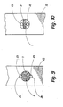
- FIGS. 9 and 10 the stresses on the thread 23 in the known hook eye needle shown in FIGS. 1 to 4 are fundamentally different from those for the hook eye needle according to the invention illustrated in FIGS. 5 to 8:
- the thread 23 of the U-shaped thread loop is laterally squeezed at 24 between the edge of the pre-punched hole in the work piece 22 and the needle head 3 in the area of the throat 8, whereby it is partially forced to create the needle shaft 1 To expand the opening in the work item 22 locally.
- the result of this is that the thread 23 is exposed to a high frictional stress when it is pulled through the work material 22, which leads to an excessive tensile stress on the thread loop in the region of the throat 8 and can damage or even break the thread.
- the two legs of the thread loop when pulling through the pre-pierced opening of the work material 22 in the thread spaces 14 are in any case within the outline of the cylindrical needle shaft 1 shown in dash-dotted lines in FIG. 8 at 25
- the result of this is that the thread of the thread loop is not frictionally inhibited by the work product 22 when it is pulled through the work product 22, but is essentially pulled freely and unhindered through the pre-punched hole.
- the tensile force exerted on the thread 23 in the area of the thread loop is essentially given exclusively by the thread tension specified by the thread delivery device and possibly a low resilient inherent elasticity of the hole edge in the work piece 22.
- the needle head 3 with its rectangular cross-sectional shape is essentially designed in the manner of a flat web, which leaves the thread 23 with sufficient lateral freedom of movement in the thread spaces 14 lying on both sides.
- the lateral taper at 21 of the neck part 2 can alternatively be omitted.
- the width of the hook eye 7 corresponds approximately to the thickness of the thread 23 assigned to the respective needle size, it being chosen to be slightly larger in order to ensure a free thread flow.
- the new hook eye needle shown is rotated by 90 ° about its axis after the thread loop has been pulled through the work piece 22 in order to enable the gripper to freely pass through the thread loop, as is generally necessary. Therefore, the thread guide grooves 20 are also aligned approximately axially parallel. However, embodiments are also conceivable in which the needle head 3 and the thread guide grooves 20 are twisted spirally in order to make it unnecessary in the manner explained in DE-PS 642 703 to turn the hook eye needle after it has been pulled through the work piece 22.
- All edges and transitions in the thread guide area ie in the area of the hook eye 7, the throat 8 and the needle tip 4 are perfectly rounded, which also applies to the tongue 6.
- the throat surface and all transitions in the area of the throat 8 are also highly polished and free of machining features, which has an advantageous effect on the thread flow and the needle stability.
- the two guide grooves 20 result in a perfect entry into the throat 8, while at the same time ensuring a sufficiently large free space without unnecessarily weakening the needle.
- the needle head 3 which is essentially rectangular in cross section, is rounded off at 15, as can be seen from FIG. 6. Alternatively, chamfers on the edges could also be provided.
- the height of the needle head 3 (and the tongue 6) measured in the longitudinal symmetry plane 13 can, as can be seen from FIG. 10, be somewhat smaller than the diameter of the cylindrical needle shaft 1, i.e. be somewhat smaller than the maximum needle shaft height, with the result that the needle head 3 also passes through the work item 22 essentially unimpeded through the hole punched by the needle shaft 1.
Landscapes
- Engineering & Computer Science (AREA)
- Textile Engineering (AREA)
- Mechanical Engineering (AREA)
- Sewing Machines And Sewing (AREA)
- Knitting Machines (AREA)
- Surgical Instruments (AREA)
Applications Claiming Priority (2)
| Application Number | Priority Date | Filing Date | Title |
|---|---|---|---|
| DE3642693A DE3642693C1 (de) | 1986-12-13 | 1986-12-13 | Hakennadel(auch Hakenroehrnadel)fuer Naeh-,Stick-,Heftmaschinen und dergl. |
| DE3642693 | 1986-12-13 |
Publications (3)
| Publication Number | Publication Date |
|---|---|
| EP0270780A2 true EP0270780A2 (fr) | 1988-06-15 |
| EP0270780A3 EP0270780A3 (en) | 1988-09-28 |
| EP0270780B1 EP0270780B1 (fr) | 1991-04-17 |
Family
ID=6316160
Family Applications (1)
| Application Number | Title | Priority Date | Filing Date |
|---|---|---|---|
| EP87115216A Expired - Lifetime EP0270780B1 (fr) | 1986-12-13 | 1987-10-17 | Crochet pour machine à relier, machine à broder et analogue |
Country Status (5)
| Country | Link |
|---|---|
| US (1) | US4790254A (fr) |
| EP (1) | EP0270780B1 (fr) |
| JP (1) | JPS63162290A (fr) |
| DE (2) | DE3642693C1 (fr) |
| ES (1) | ES2021674B3 (fr) |
Cited By (2)
| Publication number | Priority date | Publication date | Assignee | Title |
|---|---|---|---|---|
| WO2000017054A1 (fr) * | 1998-09-18 | 2000-03-30 | I.M.A. Industria Macchine Automatiche S.P.A. | Aiguille pour fixer une etiquette sur un sachet d'infusion a l'aide d'un fil noue intermediaire |
| EP2824229A1 (fr) * | 2013-07-10 | 2015-01-14 | Janome Sewing Machine Co., Ltd. | Enfile-aiguille de machine à coudre et machine à coudre |
Families Citing this family (8)
| Publication number | Priority date | Publication date | Assignee | Title |
|---|---|---|---|---|
| US5183063A (en) * | 1991-06-10 | 1993-02-02 | Larry Lee Ringle | Dental floss and pre-threaded leader |
| IT1305534B1 (it) | 1998-09-18 | 2001-05-09 | Ima Spa | Macchina perfezionata per il confezionamento di sacchetti filtrocontenenti un prodotto da infusione provvisti di etichetta di presa |
| JP3962948B2 (ja) * | 2002-02-28 | 2007-08-22 | 株式会社プロピア | かつら製造用針 |
| JP2008513127A (ja) * | 2004-09-17 | 2008-05-01 | オルムコ コーポレイション | 医療装置及び針製造方法 |
| JP4943767B2 (ja) * | 2006-08-10 | 2012-05-30 | オルガン針株式会社 | かぎ針 |
| US20130184523A1 (en) * | 2012-01-12 | 2013-07-18 | Microline Surgical, Inc., | Instrument tip having wire retention slot |
| US20150361602A1 (en) * | 2014-06-13 | 2015-12-17 | Consuelo Larsen | Piercing Crochet Hook |
| US11624136B1 (en) | 2017-05-26 | 2023-04-11 | Feather W. King | Serger seam hook for tucking thread tails |
Family Cites Families (9)
| Publication number | Priority date | Publication date | Assignee | Title |
|---|---|---|---|---|
| DE642703C (de) * | 1936-02-26 | 1937-03-12 | Brehmer Geb | Hakennadel zum Durchziehen einer Fadenschleife durch ein Arbeitsstueck |
| US2633721A (en) * | 1950-07-27 | 1953-04-07 | Alfred Hofmann Needle Works In | Spring beard needle and method of using same |
| US2872092A (en) * | 1956-05-21 | 1959-02-03 | Sehlow Fenton | Readily threaded needle |
| US3834599A (en) * | 1972-08-04 | 1974-09-10 | N Herr | Needle |
| JPS5045489A (fr) * | 1973-08-23 | 1975-04-23 | ||
| US3922982A (en) * | 1974-02-04 | 1975-12-02 | Cesare L Conti | Eccentric-tip hooked needle for hosiery linking machines |
| JPS57187551A (en) * | 1981-05-12 | 1982-11-18 | Matsushita Electric Ind Co Ltd | Apparatus for controlling temperature of water heater |
| US4379165A (en) * | 1981-05-18 | 1983-04-05 | Research Corporation | Anti-convulsant |
| DE3447281A1 (de) * | 1984-12-22 | 1986-06-26 | Kemptener Maschinenfabrik Gmbh, 8960 Kempten | Naehnadel fuer den einsatz an kettel- und naehkettelmaschinen |
-
1986
- 1986-12-13 DE DE3642693A patent/DE3642693C1/de not_active Expired
-
1987
- 1987-10-17 DE DE8787115216T patent/DE3769445D1/de not_active Expired - Lifetime
- 1987-10-17 EP EP87115216A patent/EP0270780B1/fr not_active Expired - Lifetime
- 1987-10-17 ES ES87115216T patent/ES2021674B3/es not_active Expired - Lifetime
- 1987-12-11 JP JP62313962A patent/JPS63162290A/ja active Pending
- 1987-12-14 US US07/147,163 patent/US4790254A/en not_active Expired - Fee Related
Cited By (4)
| Publication number | Priority date | Publication date | Assignee | Title |
|---|---|---|---|---|
| WO2000017054A1 (fr) * | 1998-09-18 | 2000-03-30 | I.M.A. Industria Macchine Automatiche S.P.A. | Aiguille pour fixer une etiquette sur un sachet d'infusion a l'aide d'un fil noue intermediaire |
| US6206256B1 (en) | 1998-09-18 | 2001-03-27 | I.M.A. Industria Macchine Automatiche S.P.A. | Needle for attaching a tag to an infusion bag using an intermediate knotted thread |
| EP2824229A1 (fr) * | 2013-07-10 | 2015-01-14 | Janome Sewing Machine Co., Ltd. | Enfile-aiguille de machine à coudre et machine à coudre |
| US9080269B2 (en) | 2013-07-10 | 2015-07-14 | Janome Sewing Machine Co., Ltd. | Needle threader of sewing machine and sewing machine |
Also Published As
| Publication number | Publication date |
|---|---|
| ES2021674B3 (es) | 1991-11-16 |
| JPS63162290A (ja) | 1988-07-05 |
| US4790254A (en) | 1988-12-13 |
| EP0270780A3 (en) | 1988-09-28 |
| DE3769445D1 (de) | 1991-05-23 |
| DE3642693C1 (de) | 1988-07-07 |
| EP0270780B1 (fr) | 1991-04-17 |
Similar Documents
| Publication | Publication Date | Title |
|---|---|---|
| EP0270780B1 (fr) | Crochet pour machine à relier, machine à broder et analogue | |
| DE2615018C2 (de) | Tuftingnadel | |
| EP2896732B1 (fr) | Aiguille à coudre avec double nervurage | |
| DE3619874A1 (de) | Greifer fuer tuftingmaschine | |
| DE2144058B2 (de) | Filznadel | |
| DE3712163A1 (de) | Atraumatische nadel | |
| DE19531727A1 (de) | Fadenabschneidvorrichtung für eine Nähmaschine | |
| EP0073380A1 (fr) | Outil de tricotage estampé pour des métiers à tricoter | |
| DE1485223C3 (fr) | ||
| WO1993006288A1 (fr) | Dispositif pour le serrage et guidage d'aiguilles a crochet pour un metier a crocheter | |
| DE3029333A1 (de) | Filznadel | |
| DE7306932U (de) | Gabelnadel | |
| DE2339538A1 (de) | Nadel | |
| DE3920408A1 (de) | Fadenzufuhreinrichtung mit wenigstens einem fadenfuehrer fuer eine rundstrickmaschine | |
| EP1052324A2 (fr) | Aiguille de machine à coudre avec chas à lèvres décalées | |
| EP1069226B1 (fr) | Aiguille de machine à coudre avec formation améliorée des boucles | |
| DE3512898C2 (fr) | ||
| DE2820958B2 (de) | Gabelnadel | |
| DE2440306A1 (de) | Nadel | |
| DE3405353A1 (de) | Wundpflaster | |
| DE19517602C1 (de) | Spitzennadel | |
| DE3512775C2 (fr) | ||
| DE963327C (de) | Einrichtung zum Zusammenschliessen von Loseblaettern | |
| DE3523211C2 (fr) | ||
| EP0725176B1 (fr) | Aiguille en particulier pour machines à broder |
Legal Events
| Date | Code | Title | Description |
|---|---|---|---|
| PUAI | Public reference made under article 153(3) epc to a published international application that has entered the european phase |
Free format text: ORIGINAL CODE: 0009012 |
|
| AK | Designated contracting states |
Kind code of ref document: A2 Designated state(s): CH DE ES FR GB IT LI |
|
| PUAL | Search report despatched |
Free format text: ORIGINAL CODE: 0009013 |
|
| AK | Designated contracting states |
Kind code of ref document: A3 Designated state(s): CH DE ES FR GB IT LI |
|
| 17P | Request for examination filed |
Effective date: 19890323 |
|
| 17Q | First examination report despatched |
Effective date: 19900912 |
|
| GRAA | (expected) grant |
Free format text: ORIGINAL CODE: 0009210 |
|
| AK | Designated contracting states |
Kind code of ref document: B1 Designated state(s): CH DE ES FR GB IT LI |
|
| ITF | It: translation for a ep patent filed | ||
| GBT | Gb: translation of ep patent filed (gb section 77(6)(a)/1977) | ||
| REF | Corresponds to: |
Ref document number: 3769445 Country of ref document: DE Date of ref document: 19910523 |
|
| ET | Fr: translation filed | ||
| PLBE | No opposition filed within time limit |
Free format text: ORIGINAL CODE: 0009261 |
|
| STAA | Information on the status of an ep patent application or granted ep patent |
Free format text: STATUS: NO OPPOSITION FILED WITHIN TIME LIMIT |
|
| 26N | No opposition filed | ||
| PGFP | Annual fee paid to national office [announced via postgrant information from national office to epo] |
Ref country code: ES Payment date: 19941018 Year of fee payment: 8 |
|
| PGFP | Annual fee paid to national office [announced via postgrant information from national office to epo] |
Ref country code: FR Payment date: 19941021 Year of fee payment: 8 |
|
| PGFP | Annual fee paid to national office [announced via postgrant information from national office to epo] |
Ref country code: CH Payment date: 19941027 Year of fee payment: 8 |
|
| PGFP | Annual fee paid to national office [announced via postgrant information from national office to epo] |
Ref country code: DE Payment date: 19941216 Year of fee payment: 8 |
|
| PGFP | Annual fee paid to national office [announced via postgrant information from national office to epo] |
Ref country code: GB Payment date: 19950913 Year of fee payment: 9 |
|
| PG25 | Lapsed in a contracting state [announced via postgrant information from national office to epo] |
Ref country code: ES Free format text: LAPSE BECAUSE OF EXPIRATION OF PROTECTION Effective date: 19951018 |
|
| PG25 | Lapsed in a contracting state [announced via postgrant information from national office to epo] |
Ref country code: LI Effective date: 19951031 Ref country code: CH Effective date: 19951031 |
|
| REG | Reference to a national code |
Ref country code: CH Ref legal event code: PL |
|
| PG25 | Lapsed in a contracting state [announced via postgrant information from national office to epo] |
Ref country code: FR Effective date: 19960628 |
|
| PG25 | Lapsed in a contracting state [announced via postgrant information from national office to epo] |
Ref country code: DE Effective date: 19960702 |
|
| REG | Reference to a national code |
Ref country code: FR Ref legal event code: ST |
|
| PG25 | Lapsed in a contracting state [announced via postgrant information from national office to epo] |
Ref country code: GB Effective date: 19961017 |
|
| GBPC | Gb: european patent ceased through non-payment of renewal fee |
Effective date: 19961017 |
|
| REG | Reference to a national code |
Ref country code: ES Ref legal event code: FD2A Effective date: 19990601 |
|
| PG25 | Lapsed in a contracting state [announced via postgrant information from national office to epo] |
Ref country code: IT Free format text: LAPSE BECAUSE OF NON-PAYMENT OF DUE FEES;WARNING: LAPSES OF ITALIAN PATENTS WITH EFFECTIVE DATE BEFORE 2007 MAY HAVE OCCURRED AT ANY TIME BEFORE 2007. THE CORRECT EFFECTIVE DATE MAY BE DIFFERENT FROM THE ONE RECORDED. Effective date: 20051017 |